
Pierre Bouguer named the point in his Traité du navire of 1746. He had probably begun to work out the theory at Le Havre about 1732, before the ten years of the geodetic expedition to Peru during which much of the book was written12,13. He called the metacentre “the term that the height of the center of gravity cannot pass, nor even attain”13, an upper limit for G, and his reason was a small-angle argument: with G at M, the ship would be indifferent between the upright and a slightly inclined position. Euler, in his Scientia navalis of 1749, reached an equivalent criterion independently, through the restoring moment13. The argument above is Bouguer’s in modern notation. In 1748, two years after the Traité appeared, the 74-gun Intrépide was inclined at Brest with two cannon hung from its side13, and the metacentric height was found to be 1.8 m.
Figures and tables have more room in landscape.
Chapter 4: Initial stability and the metacentre
Version 1.0 · last revised 5 November 2026 · corrections
Prologue: the Eastland at its dock
On the morning of Saturday 24 July 1915 the excursion steamer Eastland lay at its dock on the Chicago River, taking on passengers for the annual picnic of the employees of the Western Electric Company. It was one of five steamers chartered to carry them across Lake Michigan to Michigan City, Indiana1. Built at Port Huron, Michigan, in 1903, the ship was 265 ft (80.8 m) long between perpendiculars and 38 ft 2 in (11.6 m) in beam2. Its certificate, amended on 2 July, allowed 2,500 passengers and a crew of 70, and the gangplank was taken in when the inspectors’ count of passengers reached 2,500; with the crew there were about 2,570 people aboard1,3.
While they boarded, the ship leaned first towards the wharf and then, from about ten past seven, away from it, towards the river1,4. The engineers let water into the ballast tanks on the high side, the list stopped, and one of them said he thought they had the ship under control1. It had been listing for about 17 minutes1 when, at about 7:28, the list reached 45°. Water poured in through the open gangways and ports on the low side, and within two minutes the ship rolled over onto its port side, still tied to the wharf4, and settled on the river bottom in about 6 m of water3. The Eastland Disaster Historical Society counts 844 dead5; the American Red Cross gave 812 in its relief report6.
The ship was tied to a wharf in calm water, and nothing from outside heeled it. It turned over because of the relation between the weights on board and the hull. For small heels that relation is expressed by the metacentric height GM, the distance of the ship’s centre of gravity G below a point M, the metacentre, whose position the shape of the immersed hull fixes. The larger GM is, the more strongly a ship resists a small heel.
The Eastland had ten water-ballast tanks in its double bottom, five on each side1; the largest of them, No. 3, held between 225 and 250 tons (204 to 227 t if short tons were meant, 229 to 254 t if long tons) by the recollection of a former master3. In Chicago harbour the crew emptied tanks Nos. 2 and 3 every morning, and on 24 July they did so at about half past six1. George R. McDermott of Cornell University had, in about 1901 or 1902, recommended a hull form to the ship’s builders, whose representative drew it out as lines. Two days after the disaster he wrote to the Department of Commerce that his form had a metacentric height of about 18 inches (0.46 m) fully laden, for 1,000 passengers. He expected, but did not know, that it had been adopted for the Eastland. He believed that the ship as built was at least a deck deeper, and that this, with 2,500 passengers in place of 1,000, would change the metacentric height materially3.
Naval Constructor James Ackerson of the United States Navy sat with the federal board of inquiry. He told it that, as he understood, inclining, the test that measures the height of a ship’s centre of gravity (Chapter 10), was not the custom on the Great Lakes, and that he would not judge the stability of the ship without an inclining experiment. Without the experiment, he said, a ship that had carried 2,500 passengers for years might be presumed able to do so again if properly loaded. He also reasoned from the testimony that, if the ship had no stability without water ballast, its metacentric height would be zero with the tanks empty and negative with them partly filled3. In terms of the two points, emptying the tanks would raise G to the metacentre, and partly filled tanks would in effect put it above. The water in a partly filled tank runs to the low side as the ship heels, and this acts as if G had risen (Chapter 5).
In the schematic of Fig. 4.1, which follows Ackerson’s argument, G lies below the metacentre M while the ballast tanks are full, and a small heel produces a couple that returns the ship upright. With the tanks empty, G rises close to M. With passengers crowding the upper decks and water running to the low side of partly filled tanks, G is in effect above M, and the upright ship is unstable. It leans to one side or the other. It can rest at a new angle only if the shape of its hull restores a righting couple before flooding or capsizing occurs.
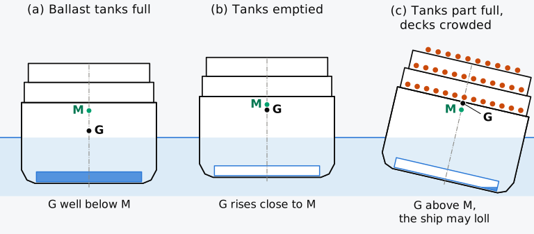
Figure 4.1 G and the upright metacentre M of a ship that depends on water ballast to stand upright. Schematic, after Ackerson’s reasoning at the 1915 inquiry, not a reconstruction of the Eastland; water ballast blue, passengers orange.
Seven inquiries were under way within three days4. In 1933 a federal court decree limited the owners’ liability. It found that the ship had turned over through the negligence of the engineer in charge of the water-ballast tanks, which had been improperly handled, and that the vessel was seaworthy if properly handled7. The Court of Appeals affirmed the decree in 1935 (In re St. Joseph-Chicago S.S. Co.)7. The supervising inspectors of the Steamboat-Inspection Service drew a broader lesson in 1915. They recommended that passenger vessels be inclined under naval architects and that no passenger vessel should depend on liquid ballast for its stability, only for its trim3. The ship was sold and rebuilt as the gunboat USS Wilmette, which served until 1945 as a training ship on the Great Lakes2.
Ackerson and McDermott both reasoned with the metacentre. Chapter 3 ended with the observation that a heeled ship rights itself when its centre of buoyancy B moves further out than the vertical through its centre of gravity G; the weight table of a ship gives G, and its hydrostatic table gives B. How far B moves for a small heel follows from the second moment of the waterplane. With the heights of B and G, this movement gives one number, the metacentric height GM, whose sign and size indicate whether the upright ship is stable and how stiff it is. We return to the Eastland in Sec. 4.9, where a ship with G above M is followed to its angle of loll.
In this chapter
By the end of this chapter you will be able to:
- find the metacentric radius of a hull from its waterplane;
- compute the metacentric height of a loaded ship, and judge from it whether the ship is stable upright;
- find the list caused by moving or loading a mass, and the loading that brings the ship upright;
- tell a loll from a list, find the angle of loll and correct it by lowering G;
- compute the longitudinal metacentric height and the moment to change trim one centimetre.
What it assumes. You need the second moments of the waterplane, Eqs. (2.13) and (2.14), and the displacement, draught and KG of a loading condition (Secs. 3.3 and 3.4).
A first reading. Sections 4.1 to 4.10 carry the main thread. The estimates of KB and BM for preliminary design in Sec. 4.4.5 can wait for a second reading, as can the derivation for a wall-sided ship in Sec. 4.7.5. The opening paragraph of that section, which extends the metacentre to a heel of any size, and the paths of B and of the metacentre that it draws for the Series 60 ship are used later in this chapter and in Chapter 8.
4.1 Stability and the righting lever
A ship floats in equilibrium when its weight and its buoyancy are equal and act along one vertical. To float upright, the ship also needs that equilibrium to be stable. Stability is a separate question from equilibrium, about what happens after a disturbance. A ship heeled slightly by a passing gust may return upright (stable equilibrium), stay at the new angle (neutral equilibrium) or heel further (unstable equilibrium).
4.1.1 Types of stability
A ship may be inclined about any axis, but because it is much longer than it is wide, inclinations across the ship and along it are treated separately8: transverse stability concerns heel, and longitudinal stability concerns trim. Transverse stability is studied in three stages (Fig. 4.2). Initial stability, at small angles of heel, is treated in this chapter. It is the small-angle part of statical stability, the stability at any angle of heel with the ship held at rest there. Statical stability is described by the righting lever over the whole range of heel, plotted as the curve of righting levers, and is treated in Chapter 8. Dynamic stability, in this sense the work needed to heel the ship, is measured by the area under the curve of righting moment and is treated in Chapter 9. The name dynamic stability is used although the calculation leaves out the velocities and accelerations of a ship rolling in waves8, and the term has other meanings as well. All three describe the intact ship. A ship whose hull has been breached and partly flooded has its own damage stability (Chapter 12), and the stability of the intact and of the damaged ship is judged against criteria set by regulation (Chapters 11 and 12). Longitudinal stability is introduced in Sec. 4.10 and applied to trim in Chapter 6.
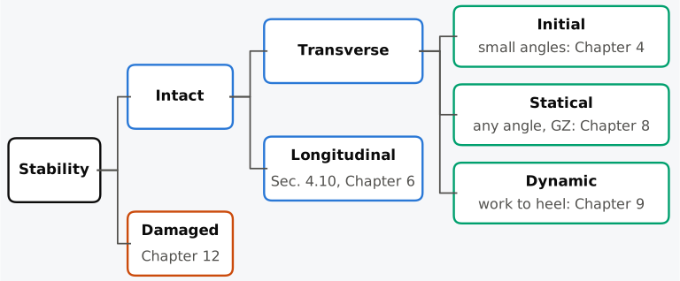
Figure 4.2 The types of stability and the chapters that treat them.
4.1.2 Heel, list and loll
A ship inclined about its longitudinal axis is said to be heeled, listed or lolled. The three words are not interchangeable, because the cause differs in each case and so does the remedy, and a master who mistakes a loll for a list can lose the ship. All three inclinations are measured by the angle , positive with the starboard side down.
Heel is the general word for any inclination about the longitudinal axis and, in its narrower sense, an inclination caused by a moment from outside the ship: wind on the side, the centrifugal force of a turn, a wave, the pull of a tow-line. Take the moment away and a stable ship comes back upright, so a heel in this sense lasts only as long as its cause, and the ship rolls about the upright. The heel caused by a given moment is found in Sec. 4.8, and the moments of wind and turning are treated in Chapter 9.
List is a steady inclination caused by the ship’s own loading. Its centre of gravity G lies off the centreline, because cargo, fuel or ballast is distributed unevenly between port and starboard, because a weight has shifted, or because a compartment on one side has flooded. For the positive-GM case considered here, bringing G back to the centreline would make the upright position stable. With G off centreline, upright is not an equilibrium: the ship inclines towards the heavy side. If its righting ability is sufficient, it reaches an equilibrium with B beneath G and rolls about that angle of list. A list persists until the loading is changed, and it is removed by bringing G back to the centreline, by moving weight towards the high side, loading on that side or discharging from the low side, in an amount calculated beforehand. The angle of list is calculated from the weight table in Sec. 4.8, where we also see how a listed ship is brought upright. Shifted, suspended and liquid loads are treated in Chapter 5, and the list caused by flooding in Chapter 12.
Loll is the steady inclination of a ship that is unstable upright, with a negative metacentric height, while G is on the centreline; the ship cannot stay upright. It may incline to either side and find a stable equilibrium where the changed immersed shape restores a righting lever. That position is the angle of loll; if no such equilibrium is available before flooding or loss of righting ability, the ship can capsize. From the bridge a loll looks like a list, but weight moved towards the high side makes it worse, and the only cure is to lower G. The loll and its correction are treated in Sec. 4.9.
Usage varies between books (Sec. 1.3.2); Barrass and Derrett9 separate heel and list by their cause, a heel coming from a force outside the ship and a list from the ship’s own weights. Here we name an inclination by its cause, and use heel for the angle itself whatever its cause. A heeling moment and a heeling lever are then the moment and the lever that incline the ship, whether the result is called a heel or a list.
4.1.3 The righting lever
When a ship heels at constant displacement, G stays where it is in the ship, provided nothing on board moves, but B does not. One side of the hull comes out of the water and the other goes deeper, and the centre of the immersed volume moves towards the side that went down, to a point (Fig. 4.3). The weight acts down through G and the buoyancy up through , and the two equal forces form a couple. Its lever, the righting lever GZ, is the horizontal distance from G to the vertical through , Z being the foot of the perpendicular from G to that vertical, and its moment is the righting moment . If Z lies on the low side of G, the couple turns the ship back towards upright and GZ is counted positive; if it lies on the high side, the couple heels the ship further and GZ is negative, and the moment is then called a capsizing moment9.
Shipboard practice calls the moment of statical stability and states it in tonne-metres, as the displacement mass times the lever9. It is a moment of mass; the righting moment is the moment of a force and is given in kN·m. A lever of 0.1 m gives a righting moment of 7561 kN·m on a ship of displacement mass 7707 t and a smaller moment on a lighter ship; two conditions with equal GZ do not resist a given heeling moment equally.
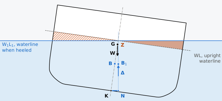
Figure 4.3 The righting lever of the Series 60 hull in the departure condition of Table 3.1, heeled 8° and seen from aft. Midship section to scale; emerged wedge hatched, immersed wedge shaded; dotted, the vertical through .
At 8° the righting lever of this ship is 96 mm, too short to see when drawn to scale as in Fig. 4.3, and B has moved only 0.44 m across a section 16 m wide. Movements of B this small determine whether a ship of several thousand tonnes comes back upright. For a small heel the movement of B follows from the waterplane, and it defines the metacentre M; with G, the metacentre gives the metacentric height GM and, for small angles, the righting lever.
4.2 Movement of the centre of buoyancy in a heel
4.2.1 The two wedges
To find that movement, heel the ship through a small angle without changing its displacement. The waterline moves from WL to (Figs. 4.3 and 4.4). On the side that rises, a wedge of the hull comes out of the water; on the side that goes down, a wedge goes under. Because the displacement is unchanged, the two wedges have equal volumes . The immersed volume changes as if the emerged wedge had been cut away and attached on the other side: a volume has moved from the centroid of the first wedge to the centroid of the second. Taking moments of the volumes, as for masses, shows that moving part of a volume moves the centroid of the whole parallel to the movement, by the moved volume times the distance moved divided by the whole. The centre of buoyancy therefore moves from B to , parallel to , through
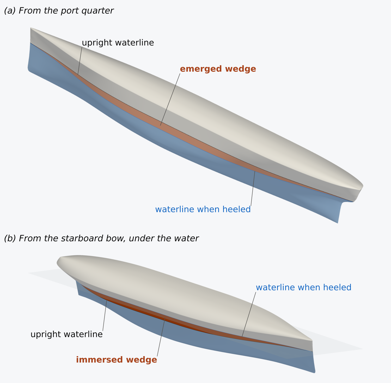
Figure 4.4 The wedges of a heel on the Series 60 hull, heeled 12° at the displacement of the departure condition: (a) the emerged wedge, (b) the immersed wedge. The shaded bands are where the wedges meet the hull.
For a heel the two wedges are mirror images, and the waterlines WL and cross on the centreline. This is exact for a ship whose sides are vertical where the water meets them, and holds to first order in for any ship symmetric about its centreplane. The line about which the waterplane turns passes through the centroid of the waterplane, because only then do the two wedges have equal volumes10; for a ship heeled at its upright trim, this line is the centreline of the waterplane. A small heel of a symmetric ship produces no first-order trim, because the product of inertia of its waterplane is zero10, and the trim is held fixed in what follows.
4.2.2 The moment of the wedges
The wedges are found strip by strip (Fig. 4.5). Take a thin slice of the ship of length at a station where the half-breadth of the waterline is . On each side the wedge is a triangle with sides and , so its volume is , and its centroid lies two thirds of the way out from the axis, at . Moving the emerged triangle to the immersed side moves it through . Adding the slices over the length gives the moment of the moved volume about the centreline:
where is the transverse second moment of the waterplane about its centreline. Its integrand is the cube of the half-breadth, for which Chapman printed a table of cubes (Chapter 2). For a rectangular waterplane, along the whole length, and the integral gives .
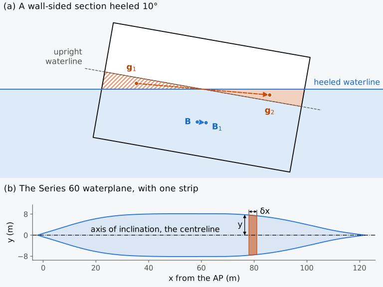
Figure 4.5 The wedges of a small heel: (a) a wall-sided section 12 m wide, heeled 10°, with the emerged wedge hatched and the immersed wedge shaded; (b) the design waterplane of the Series 60 hull, with one strip.
4.3 The metacentre and the metacentric radius
4.3.1 The metacentric radius
Combining Eqs. (4.1) and (4.2), the centre of buoyancy moves through . For a small angle, B moves along an arc whose centre lies on the centreline of the upright ship: the vertical through , which is normal to the new waterline, crosses the centreline at a point M, and . Comparing the two expressions,
The point M is the metacentre: the point at which the vertical through the centre of buoyancy of the ship heeled through a small angle meets the vertical through the centre of buoyancy of the upright ship, in the limit as the angle tends to zero11. Strictly it is the transverse metacentre; for a change of trim there is a longitudinal metacentre. Unlike G and B, which are the centres of a real distribution of mass and of a real volume, M is a point of construction, where the lines of action of the buoyancy in the upright and the slightly heeled positions cross. The distance BM is the metacentric radius, the radius of curvature of the path of B at the upright position10,11. It depends only on the hull and the draught, on the shape of the waterplane and on the volume below it.
Historical note: Bouguer and the metacentre
4.3.2 Effect of breadth, draught and fullness on BM
Predict 4.1. Two pontoons have rectangular sections and equal displacements and draughts. One pontoon is 12 m wide; the other is 6 m wide and twice as long. Which has the larger metacentric radius, and by what factor?
For the box barge, whose centre of buoyancy lies at half the draught, Eq. (4.3) gives
where KB is the height of B above the keel K. The waterplane and the volume of a ship can be compared with those of the box. Write the second moment of the waterplane as , where is the transverse inertia coefficient, 1 for a rectangle, and the displaced volume as , with the block coefficient . Equation (4.3) then becomes
For hulls of the same shape, which share the ratio , BM grows with the square of the breadth and falls with the draught, and wide, shallow hulls have a large metacentric radius. The fullness of the hull enters only through that ratio. A box with the Wigley hull’s breadth and draught, 10 m and 6.25 m, has = 1.333 m. The Wigley hull has a slightly larger BM, 1.371 m, because its waterplane is less full than the box’s and its volume less full still: its is 48/105 = 0.457 and its is 4/9, which give = 1.029. For the Series 60 hull at its design draught, = 0.544 and = 0.598, which give BM = 3.08 m.
Any hull of constant section gives BM , with a coefficient that depends on the shape of the section (Exercise 4.6), and for a ship . Attwood14 quoted White’s range of 0.08 to 0.1, with 0.09 as a usual value for the merchant ships of his day, and the Series 60 hull gives 0.075 in its departure condition.
4.4 The metacentric height
4.4.1 KB, BM, KM and GM
The metacentric radius places M above B, KB comes from the hydrostatic table and KG from the weight table (Chapter 3), and together they give the number by which initial stability is judged. Measured from the keel, the metacentre lies at
and its height above the centre of gravity is the metacentric height
GM is positive when M lies above G11. The four points are drawn on one vertical in Fig. 4.6 for the Series 60 ship in its departure condition, whose metacentre lies 6.55 m above the keel. KB and BM, and so KM, are properties of the hull at its draught and are collected in the hydrostatic curves; KG is a property of the loading, found from the weight table. The metacentric height combines the two, and a given hull may have a large GM in one condition and a negative GM in another, as Ackerson reasoned the Eastland did.
Predict 4.2. Take a ship of 3,000 t whose centre of gravity is 5.00 m above the keel, and pump out 230 t of water ballast from a double-bottom tank whose contents have their centre 0.60 m above the keel. How high is the centre of gravity of what remains? (These are round numbers, not data for the Eastland.)
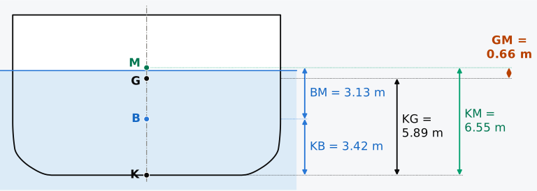
Figure 4.6 K, B, G and M on the centreline of the Series 60 ship in the departure condition. Midship section to scale; KB and BM depend on the hull and the draught, KG on the masses aboard.
The sign of GM determines the stability of the upright ship. If M is above G, the couple of a small heel rights the ship and the upright equilibrium is stable; if M is below G, the couple heels it further and the upright ship is unstable. If M and G coincide, a small heel produces no righting moment to first order in the heel, and stability is then decided by how the metacentre moves as the ship heels: for a wall-sided ship, by the term in of the wall-sided formula (Sec. 4.7.2).
4.4.2 GZ and the metacentric height
If the metacentre stays fixed as the ship heels, the vertical through always passes through M, and the right-angled triangle GZM of Fig. 4.7 gives
with the displacement as a force. For small angles in radians, so the righting lever grows linearly with the heel, with slope GM per radian. On a curve of righting levers against heel, the tangent at the origin passes through the point GM at 57.3°, one radian8.
With the metacentre fixed, Eq. (4.8) is also the restoring moment of a pendulum of length GM hung from M, whose bob, at G, carries the ship’s weight. The buoyancy of the heeled ship acts through M, as the pull of a string acts through the point from which a pendulum hangs, so that only the weight at G has a moment about M. The ship rights itself while G hangs below M, and it heels further when G lies above M, as a pendulum balanced above its pivot falls. The analogy concerns only the moment that resists a small heel and does not describe the motion of the ship.
In Fig. 4.7, drawn for the Series 60 ship heeled 8°, the vertical through crosses the centreline 28 mm above M, because the metacentre rises slightly as the ship heels. The triangle GZM, and with it GZ = GM sin φ, therefore holds only for small heels. At 8° GM sin φ still comes close to the righting lever computed on the heeled hull; how far the relation holds for this ship is measured in Sec. 4.7.3.
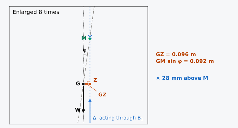
Figure 4.7 The triangle GZM of the Series 60 ship in the departure condition, heeled 8°: the neighbourhood of G in Fig. 4.3, enlarged eight times. Dash-dotted, the centreline; dotted, the verticals through G and ; ×, where the latter crosses the centreline.
Since GM = KM − KG, Eq. (4.8) can also be written GZ = KM sin φ − KG sin φ. With G on the centreline, KG sin φ is the horizontal distance of G from the keel point K. The horizontal distance from K to the vertical through is written KN, N being the foot of the perpendicular from K to that vertical (Fig. 4.3). At any heel, then,
and KN equals KM sin φ for small heels10,15. KN is the righting lever that the ship would have with G at the keel. It depends only on the hull, its displacement, the heel and the trim, held at zero here; KG comes from the loading. Moving a weight down within the ship therefore lengthens the lever at every heel, by the fall of G times sin φ. For the Series 60 ship heeled 8°, the heeled hull gives KN = 0.915 m, against KM sin φ = 0.911 m, and GZ = 0.915 − 5.887 sin 8° = 0.096 m.
4.4.3 Limits on the position of G
The condition for initial stability is GM > 0, with G below M, the limit that Bouguer set for G. The older statement that G must lie below B, which Stevin took to be required for stability13, is sufficient but not necessary10 (Fig. 4.8). The box barge, 12 m wide and floating at 3 m, has its G 2.50 m above B. Heeled 15°, its centre of buoyancy still moves out beyond the vertical through G and the couple rights it, because BM = 4.00 m carries M 1.50 m above G. A box half as wide, with the draught and KG of the barge, has a quarter of that BM, and M lies 1.50 m below G; heeled 15°, it is turned further over. The only difference between the two boxes is the breadth of their waterplanes. A body that floats wholly under water has no waterplane, and BM = 0; its centre of buoyancy stays fixed in the body however the body is inclined, and M coincides with B. Such a body is stable only if G lies below B, and then equally against small inclinations about either horizontal axis; rotation about the vertical remains neutral. For a submerged submarine this is the condition of stability in both roll and pitch8. The submarine acts as a pendulum hung from B, of length GB, the height of B above G8.
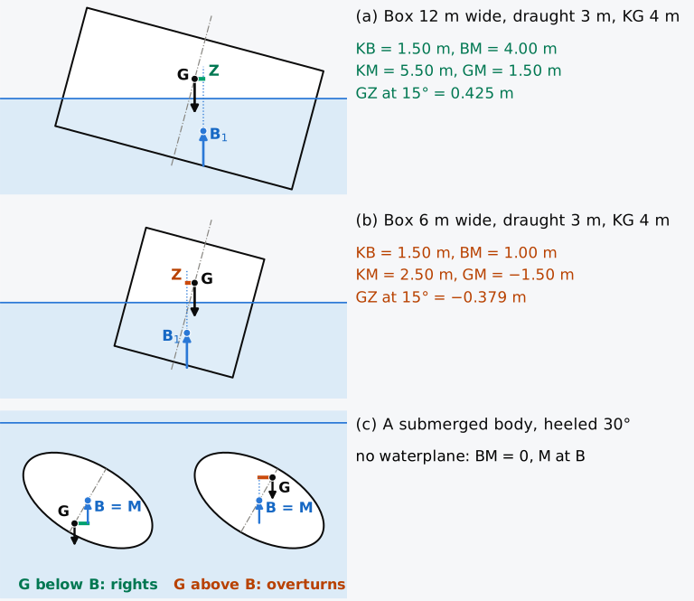
Figure 4.8 The position of G and initial stability: (a) the box barge, stable with G 2.50 m above B; (b) a box half as wide, with KG unchanged, unstable; (c) a body wholly under water, stable only with G below B. Sections (a) and (b) to scale; (c) schematic.
4.4.4 The metacentres of the reference hulls
Example 4.1. The metacentre of the box barge. A box barge 60 m long, 12 m wide and 6 m deep floats in sea water at a draught of 3.0 m with its centre of gravity 4.0 m above the keel. Find KB, BM, KM and GM, and the righting moment when it is heeled 5°. At what draught would its metacentre be lowest?
Optional exercise: compare the box-barge calculation with the hydrostatics tool.
Example 4.2. The metacentre of the Wigley hull. The Wigley hull is 100 m long and 10 m wide and floats at its design draught of 6.25 m. The second moment of its waterplane is m⁴, its displaced volume is m³ and its centre of buoyancy is at . Find KM, and the highest KG at which the hull would have a metacentric height of at least 0.15 m.
Example 4.3. The metacentric height of the loaded Series 60 ship. In its departure condition (Table 3.1), the Series 60 ship displaces 7707 t in sea water, floats at an even-keel draught of 6.367 m and has KG = 5.887 m. At that draught, interpolation in the hydrostatic table gives KB = 3.417 m, and the transverse second moment of the waterplane is 23,528 m⁴. Find BM, KM and GM, and estimate the righting moment at 5°.
4.4.5 Estimating KB and BM
Before a hull is defined in detail, KB and BM can be estimated from its dimensions and its coefficients of form. For KB, the curve of waterplane area against draught is replaced by a figure of straight lines through its ends that encloses an equal area, and the depth of the centroid of that figure is taken as the depth of B. This places B below the waterline by a third of , which is Morrish’s formula, also attributed to Normand9:
It is exact for a box; for the Wigley hull at its design draught, with m, it gives 3.819 m, 0.087 m below the exact 3.906 m. For the Series 60 ship in its departure condition, with = 6.367 m, = 7519.0 m³ and = 1394.7 m², it gives 3.509 m, against 3.417 m from the hull. An error of 9 cm in KB is an error of 9 cm in GM, 14 % of the ship’s GM in that condition. Morrish’s formula serves for preliminary estimates, and the KB of a defined hull is integrated and tabulated against the draught.
Equation (4.5) gives BM from the coefficients of form, but its inertia coefficient depends on how the breadth varies along the waterplane, which is not known before the waterplane is drawn. The waterplane coefficient depends only on its area, and taking as gives the estimate15
For the Wigley hull and ; the estimate is then the BM of a box with the hull’s breadth and draught, 1.333 m, 2.8 % below the exact 1.371 m. For the Series 60 hull at its design draught, with = 0.708, is 0.501 against = 0.544, and the estimate is 2.84 m against 3.08 m, 8 % low. In the departure condition it is 0.25 m low, more than a third of the ship’s GM of 0.659 m, and this estimate also serves only for preliminary work.
4.5 Variation of the metacentre with draught
So far KM has been found at one draught, but a ship is loaded through a range of draughts. As a ship is loaded, KB rises roughly in proportion to the draught. How BM changes depends on how the waterplane grows compared with the volume below it. A box keeps its waterplane unchanged as it sinks, so its BM falls as the volume grows, and its KM falls at light draughts and rises again at deep draughts. In a hull whose waterline widens quickly as it sinks, grows with the cube of the breadth, BM can rise with the draught, and KM then rises with the draught from near the keel, as for the Wigley hull with its parabolic sections, which narrow to the keel (Fig. 4.9(b)). The Series 60 ship, with a flat bottom and nearly vertical sides over most of its length, behaves like the box. Plotting KB and KM against draught, with the line that marks the waterline, gives the metacentric diagram (Fig. 4.9). It is also drawn about a line at 45° to the axis of draught14,16, which is the line when both axes share one scale. Drawn either way, the diagram gives the height of the metacentre at any draught, and where G must be for a given GM.
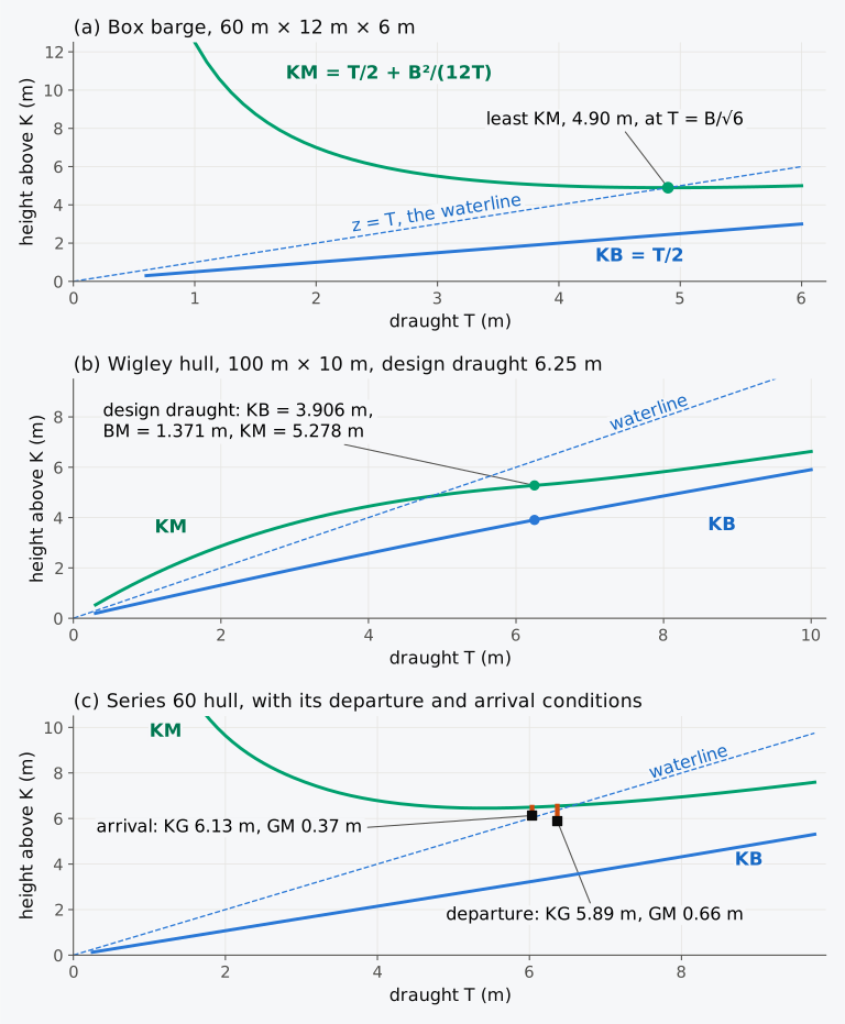
Figure 4.9 Metacentric diagrams of the three reference hulls, with the departure and arrival conditions on the Series 60 diagram (squares, G; bars, GM).
For the box barge, , which is least at ; at that draught M lies in the waterline, above it at lighter draughts and below it at deeper draughts. The metacentre of the Wigley hull also lies above the waterline at light draughts and below it at deep draughts, and it crosses the waterline at a draught of about 4.8 m, close to the 4.90 m of the box barge. The KM of the Series 60 hull falls from more than 10 m at light draughts to a broad minimum of 6.45 m at a draught of 5.40 m. The loaded conditions lie on the flat part of the curve, and between the departure and arrival conditions, whose draughts differ by 0.33 m, KM differs by 0.05 m.
Equation (4.5) compares hulls of the same shape; it does not describe one hull at different draughts, because the waterline breadth and the ratio then change too. Each waterline of the Wigley hull is the design waterline scaled in breadth, so its is 0.457 at every draught, but its waterline breadth and its both fall towards the keel. Its BM is 0.649 m at a draught of 0.625 m, 1.851 m at 3.125 m and 1.371 m at 6.25 m; it rises to a largest value of 1.88 m near a draught of 3.7 m and falls above it, as the distance between the curves of KM and KB in Fig. 4.9(b) shows.
Since the KM of the Series 60 ship is nearly constant at its loaded draughts, its departure and arrival conditions differ in GM mainly because of G. Between departure and arrival, the consumption of fuel, fresh water and stores lightens the ship by 471 t and raises G by 0.24 m, to 6.13 m, because what was consumed lay below G on average, while KM falls by only 0.05 m. GM falls from 0.66 m to 0.37 m on the voyage. An officer can read KM for each condition from a metacentric diagram or from the hydrostatic table; both assume even keel. The arrival condition, solved on the whole hull, trims 0.77 m by the head, and at that waterline KM is 6.464 m, 3 cm less than at even keel, so its GM is 0.34 m rather than 0.37 m. Stability information for real ships accounts for trim (Sec. 4.11). All these values are solid metacentric heights, with G found from the weight table and not corrected for free surfaces; the partly filled tanks of the two conditions reduce them, and the correction for them is made in Chapter 5.
4.6 Metacentric height and the roll
The voyage reduced the GM of the Series 60 ship from 0.66 m to 0.37 m. A suitable GM has a lower bound and an upper bound, and the lower bound comes from what the ship must withstand. A passenger ship must survive the flooding of part of its hull without capsizing or taking a large list, and it must not heel far when its passengers crowd to one side. A strong wind on the beam must not give any ship a serious list. Crowding heels a ship most where the passengers are heavy compared with the ship, as in an excursion steamer like the Eastland, and there it can call for a large GM. Beyond these needs, GM should keep only a modest margin8. The upper bound comes from the roll. A large GM gives a large righting moment but also a stiff ship with a short, quick roll, whose accelerations strain people and cargo lashings10. A small GM gives a tender ship, with a gentle roll and little reserve. Barrass and Derrett give illustrative fully loaded values of 0.30 to 0.50 m for general cargo ships, 1.5 to 2.5 m for container ships and 2 to 3 m for ore carriers in their 2006 text9. These are historical examples, not limits to apply to a new ship; its approved stability and cargo-securing information determine the working range.
The link between GM and the roll follows from the equation of motion. A ship released from a small heel in calm water rolls about a longitudinal axis near G, and not about M, from which the pendulum of Sec. 4.4.2 hangs. Its mass moment of inertia about that axis is , where is the radius of gyration, or gyradius, in roll, and the righting moment, which for small angles is , opposes the heel. Neglecting damping,
where is the natural period of roll, the time of one complete roll from one side to the other and back9,10. As long as the angles are small, the period does not depend on the amplitude; it grows with the radius of gyration and falls as GM grows. Equation (4.10) is for an unresisted roll10, and it also leaves out the water that moves with the hull, which adds to the inertia and lengthens the period. The radius of gyration is seldom known before a ship is built, and is usually taken in proportion to the breadth: Barrass and Derrett9 give about 0.35, and Biran and López-Pulido10 quote for merchant ships and 0.35 as used by some shipyards. Where better information is lacking, the IS Code estimates the period for its weather criterion, a check of the ship against a steady wind and a roll (Chapters 9 and 11), as
with in seconds and the lengths in metres, and with GM corrected for free surfaces17. The Code writes for the period and for the draught. Since = 2.006 s/m1/2, the Code’s formula has the form of Eq. (4.10) with . Because the coefficient is an estimate for ships rolling in water, is best read as an effective radius of gyration that includes the water moving with the hull. It is not directly comparable with the radius of gyration of the ship’s mass, which excludes that water.
By Kempf’s non-dimensional factor , the roll period in units of , a roll with a factor below 8 is stiff, between 8 and 14 comfortable, and above 14 tender10. Barrass and Derrett9 give periods in seconds that do not depend on the breadth: as short as 8 s for a stiff ship with a GM of 2 to 3 m, 25 to 35 s for a tender ship with a GM of 0.16 to 0.20 m, and 15 to 25 s as generally acceptable for those on board. The two measures do not agree; for the Series 60 ship, 16.256 m wide, Kempf’s factor of 14 is a period of 18.0 s, which lies inside Barrass and Derrett’s acceptable range. The IS Code’s estimate for the Series 60 ship is plotted with Kempf’s ranges in Fig. 4.10.
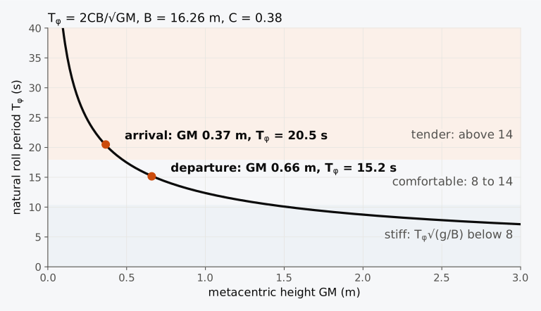
Figure 4.10 The natural roll period of the Series 60 ship by the IS Code’s formula, with Kempf’s ranges. The departure and arrival conditions use their own , 0.379 and 0.382, and the solid GM.
Example 4.4. The roll period of the Series 60 ship. In its departure condition the Series 60 ship, 16.256 m wide, floats at a draught of 6.367 m with a waterline 123.69 m long and GM = 0.659 m. Estimate its natural roll period by the IS Code’s formula and find Kempf’s factor. Below what GM would the ship be tender by Kempf’s measure? Use the solid GM; the IS Code takes GM corrected for free surface.
Solved for GM, Eq. (4.10) gives GM from a timed roll if the radius of gyration is known. The period lengthens as GM falls, and the IS Code advises the skippers of fishing vessels to time the roll while ice forms on the vessel and to act at once if the period increases noticeably17.
4.7 The limits of GM sin φ and the wall-sided formula
4.7.1 Range of validity of GM sin φ
The righting moments and the roll period found so far all rest on GZ = GM sin φ, the lever that the ship would have if its metacentre stayed where it is when upright. Taken as exact at every heel, the relation would give the Series 60 ship in its departure condition a lever that grows to 0.659 m on its beam ends and stays positive until the ship is upside down. It would miss any earlier angle at which the ship loses its righting ability. On the heeled hull, with the trim held at zero, the lever is largest, 0.54 m, near 37°, and at 60° it has fallen to 0.22 m, against 0.57 m by GM sin φ. Books disagree on how far the relation can be trusted. Moore8 says about 7°, and Tupper16 about 10° for most conventional forms. Barrass and Derrett9 give about 15°, and Biran and López-Pulido10 between 5° and 15°, depending on the form and the loading. The range depends on the ship, and for a given ship it can be found by heeling the whole hull.
Predict 4.3. For the Series 60 ship in its departure condition, GM sin 10° = 0.114 m. If the whole hull were heeled to 10° and its GZ computed, would it be larger or smaller than 0.114 m? Think about how the breadth of the waterline of a ship with vertical sides changes as it heels.
4.7.2 The wall-sided formula
For a ship whose sides are vertical over the band that goes in and out of the water, the movement of B can be found for any angle in that band, not only for a small angle. Figure 4.11 shows a box section heeled 20°, drawn in the frame of the ship, in which the water surface is inclined. Because the sides are vertical over the band, the waterlines still cross on the centreline, and in a slice of length where the half-breadth is each wedge is a right triangle with legs and ; the two triangles are congruent. Each has an area , with its centroid out from the centreline and above or below the upright waterline. Moving the emerged wedge to the immersed side moves its centroid from to , across by and up by . The moments of the moved volume about the centreline and about the upright waterline are therefore
using . Dividing by , B moves, in the frame of the ship,
The righting lever is the horizontal distance between the verticals through G and . Projecting the movement of B, and the height BG of G above B, on the horizontal, which is parallel to (Fig. 4.11(b)), gives
and since , the wall-sided formula8,16
The bracket is the height above G of the point M′ where the vertical through meets the centreline (Fig. 4.11(a)), which lies above M.
With GM = 0, the wall-sided formula gives , a righting lever on either side. A wall-sided ship whose metacentre is at G is weakly stable upright, because its metacentre rises as it heels16. Many books call the case GM = 0 neutral equilibrium9, which is true to first order in . It holds at all angles only where the metacentre does not move as the body heels; a body of revolution floating with its axis horizontal and G on the axis, like a circular section, is neutral at every angle.
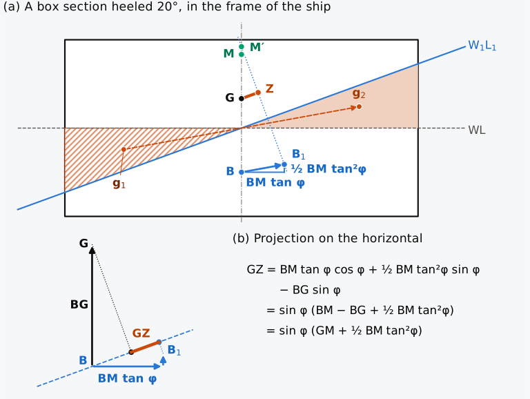
Figure 4.11 The wall-sided formula: (a) a box section 12 m wide, floating at a draught of 3 m with KG = 4 m, heeled 20° and drawn in the frame of the ship, with the vertical through dotted; (b) the movements of B and the height of G projected on the horizontal, dashed. To scale.
The formula holds as long as the sides are vertical in the band, that is, until the deck edge goes under or the bilge comes out. For a box of breadth , freeboard and draught , the deck edge reaches the water at and the bottom corner leaves it at ; for a box 12 m wide with = 3 m, both happen at 26.6°. At 20° the box has m, m and = 1.50 m, so that m, against 0.513 m by GM sin φ. At 5° the formula, which is exact for the box, gives GZ = 0.1321 m, 1 % more than GM sin φ. For full hull forms the formula is often reasonably accurate up to about 10° of heel16.
4.7.3 The righting lever of the whole hull
Figure 4.12 compares the righting lever of the Series 60 ship, computed by heeling the whole hull at constant displacement, with GM sin φ and the wall-sided formula. The computed lever and GM sin φ agree at small angles; the slope of the computed curve at the origin gives GM = 0.660 m, against 0.659 m from KM − KG, a check on both calculations. At 5° the heeled hull gives GZ = 0.05839 m and a righting moment of 4415 kN·m, against 0.05744 m and 4343 kN·m by GM sin φ. Beyond a few degrees the computed GZ grows faster, and GM sin φ falls short of it by 1.6 % at 5°, 5 % at 8.9°, 10 % at 12.6° and 23 % at 20°, each a fraction of the computed GZ. For this ship, in this condition, “small” means less than about 9° if a 5 % error is acceptable.
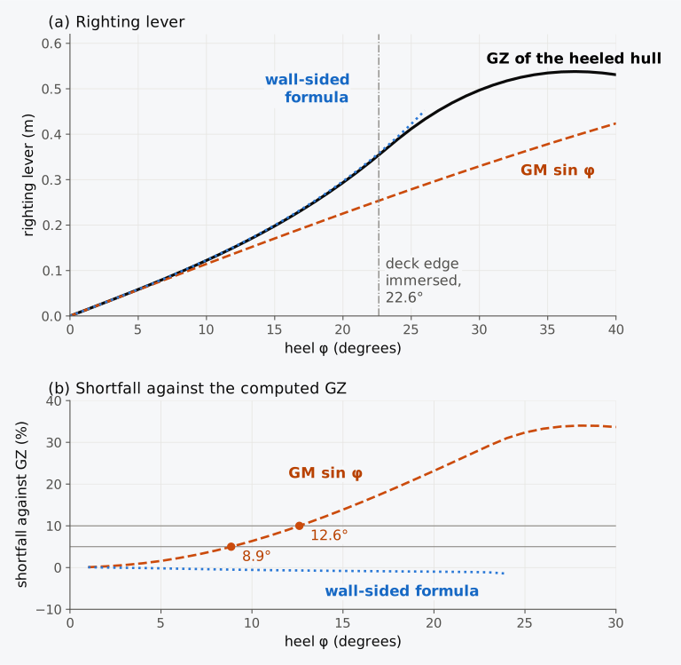
Figure 4.12 The righting lever of the Series 60 ship in the departure condition at small and moderate angles, computed on the heeled hull and estimated by GM sin φ and by the wall-sided formula.
The Series 60 ship has nearly vertical sides over most of its length where the water meets them, and the wall-sided formula follows its computed lever closely. In the departure condition the freeboard amidships is 3.39 m and the half-breadth 8.13 m, so the deck edge reaches the water at about , and up to that angle the wall-sided formula agrees with the computed GZ to within about 1 % (Fig. 4.12). Beyond it the immersed deck no longer adds breadth to the waterplane, and the computed lever falls below the formula. The freeboard does not enter GM, but it bounds the range of the formula, and beyond that range the freeboard matters most. GM is therefore an incomplete measure of the stability of a ship.
The second term of the wall-sided formula measures the error of the small-angle relation. The righting lever of a wall-sided ship exceeds GM sin φ by
which is a fraction of GM sin φ. Figure 4.12 gives the shortfall as a fraction of GZ, and an excess of 5.3 % is a shortfall of 5 %. The range of the small-angle relation depends on the ratio BM/GM rather than on a fixed angle. With BM/GM = 2, GM sin φ is within 1 % of GZ up to about 6°; for the Series 60 ship, whose BM/GM is 4.7, the excess is 7.4 % at 10°, against the 6.8 % computed for the whole hull. GM sin φ fails soonest for a tender ship, with a small GM and a large BM.
4.7.4 Captain and Monarch
Now that you have the righting lever, the metacentre and GM sin φ, and have seen in Fig. 4.12 what happens to the lever of the Series 60 ship once its deck edge goes under, we can look again at the two ships of the prologue of Chapter 1. Attwood drew the curves of righting levers of HMS Captain, lost in a gale in 1870, and of its contemporary HMS Monarch, both masted ships with their guns in revolving turrets. Captain combined heavy masts and sails with a low freeboard and had come out heavier than designed, although the sources differ on how much. In one account, when launched, the ship was “more than two feet deeper in the water than designed”18 (more than 0.6 m); in the figures given to the House of Lords in 1871, its freeboard was 6 ft 6 in (2.0 m) against the 8 ft (2.4 m) intended, 1 ft 6 in (0.46 m) less19. Both have the ship floating deeper than designed. Monarch, designed by Edward Reed18, had a freeboard of about 14 ft (4.3 m).
Attwood14 used the two ships to introduce his students to the curve of righting levers, and tabulated the righting lever of each at intervals of 7°; his first two values for each ship are given in Table 4.1.
Table 4.1 Righting levers of HMS Captain and HMS Monarch at small angles of heel, from Attwood14.
| Heel | 7° | 14° |
|---|---|---|
| GZ of Captain (m) | 0.11 | 0.22 |
| GZ of Monarch (m) | 0.10 | 0.21 |
Divided by sin φ, they correspond to metacentric heights of about 0.9 m for Captain and 0.8 to 0.9 m for Monarch. Attwood gives no metacentric heights; these values are calculated here from his levers, which he gives to the quarter inch. At 7° and 14° the ratio GZ/sin φ already includes a little of the excess over GM sin φ, and the values slightly overstate GM. Judged by GM, the two ships were nearly equal, with Captain slightly the stiffer, and an inclining experiment would have ranked them in this order.
Predict 4.4. At small angles of heel the two ships resisted heeling almost equally, as Table 4.1 shows. Captain’s deck stood about 2.0 m above the water and Monarch’s about 4.3 m. Which ship would you expect to keep resisting better when heeled to 40°, and why? Decide before you look at Fig. 4.13.
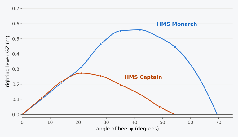
Figure 4.13 Righting levers of HMS Captain and HMS Monarch, from Attwood14, drawn smoothly through his points. Attwood gives no values for Monarch between 54½° and 69½°, where its lever vanishes, and that part of the curve is interpolated.
At small angles the two curves of Fig. 4.13, drawn through all of Attwood’s values, almost coincide, as in Table 4.1, and GM sin φ would describe either ship. The curves separate beyond about 20°. Captain’s lever reaches its maximum, 0.27 m, at about 21° and then decreases until it vanishes at 54½°; beyond that angle the couple heels the ship further. Monarch’s lever keeps increasing up to about 40°, is still 0.44 m at 54½°, and does not vanish until 69½°. Attwood pointed to the difference in their freeboard14. With little hull above the water, Captain put its deck edge under at a moderate angle, and from that point each further degree of heel added less to the righting lever than the degree before, as for the Series 60 ship once its deck edge was immersed. The difference between the two ships lay beyond the range of GM sin φ, in the shape of each hull above the water, and the righting lever at such angles is computed in Chapter 8. The areas under these curves give the work needed to heel each ship, the subject of Chapter 9.
4.7.5 The path of the metacentre
The idea of the metacentre extends to a heel of any size. As the ship heels, B moves along a curve (Fig. 4.14). A further small heel from any angle moves B parallel to the line joining the centroids of the two new wedges, and as the wedges shrink that line tends to the waterline. In the limit, the tangent to the path of B at each angle is parallel to the waterline at that angle10. The buoyancy acts normal to the waterline, and so normal to the path, and the verticals through B at neighbouring angles cross at the centre of curvature of the path. The point where they cross is the metacentre for that angle, and its path is the evolute of the path of B10. At zero heel it is the metacentre M.
For a wall-sided ship both paths follow from Eq. (4.12). In the frame of the ship B moves across by and up by , the square of the movement across divided by , and its path is a parabola with its vertex at B. Its radius of curvature at the heel is . This radius is for the heeled waterplane10, which is wider than the upright waterplane by the factor . The metacentre for that heel is the centre of curvature. It lies on the vertical through , a distance from , and in the frame of the ship that vertical is inclined at to the centreline. The distance therefore has the components up and towards the high side. Added to the movement of B, with , they place the metacentre
higher than the point M′ of Fig. 4.11, which lies above B. For the Series 60 ship, with KB = 3.417 m and BM = 3.129 m, these give a metacentre 6.64 m above the keel at 8°, 6.88 m at 15° and 7.36 m at 22.6°, where the deck edge reaches the water. The whole hull gives 6.63, 6.87 and 7.33 m, and up to that angle the two paths of B differ by about 4 mm at most. On the whole hull the metacentre rises from 6.55 m upright to 7.37 m at about 23° and then falls as the deck edge goes under and the waterplane narrows; because of this rise, GZ grows faster than GM sin φ. The cross in Fig. 4.7, 28 mm above M at 8°, is the point M′ of Fig. 4.11 for the whole hull, where the vertical through meets the centreline; it lies above M because the metacentre rises as the ship heels.
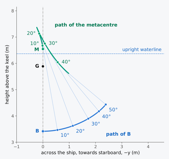
Figure 4.14 The paths of B and of the metacentre of the Series 60 ship in the departure condition as it heels, in the frame of the ship. Dotted, the vertical through B at each angle.
Animation 4.1 shows the whole-hull calculation as the ship heels, with the righting lever traced against the heel.
Animation 4.1 The Series 60 ship in the departure condition heeled from upright to 50° and back. Above, the midship section to scale, with the centre of buoyancy of the whole hull at the heel shown, labelled B (B1 in the text), the centre of gravity G, the weight and buoyancy as arrows, and the righting lever GZ in orange. Below, GZ traced against the heel as the ship turns, over the whole curve in grey, with GM sin φ dashed; the deck edge goes under at 22.6°, and GZ reaches its maximum, 0.54 m, near 37°. Each frame is the whole hull heeled to the angle shown, at constant displacement with the trim held at zero. No sound; 12 s.
4.8 Heeling moments and the angle of list
4.8.1 Causes of heel
So far the ship has been heeled without saying by what. With GM, and the wall-sided formula where GM sin φ falls short, you can now work out how far a given moment heels it, once the moment is known. A ship at rest in calm water with G on the centreline and GM positive floats upright, and several moments can heel it from that condition (Fig. 4.15). A mass moved across the deck moves G off the centreline. Wind blowing on the side above the water is resisted by the water below it, and the two forces form a couple. A ship turning at speed is pushed sideways at G by the centrifugal force and held by the water force on the hull, and it heels away from the centre of the turn. A load lifted by the ship’s own crane acts at the head of the crane as soon as it leaves the deck. Grounding and towing heel ships too8. Here we consider the first of these moments, which the ship’s own loading produces, and the list it causes: its angle, found from the weight table, and the loading that brings the ship upright again.
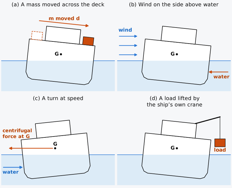
Figure 4.15 Moments that heel a ship (schematic).
4.8.2 The angle of list
The ship is in equilibrium where the righting moment equals the heeling moment , , or where the curve of righting levers meets the heeling lever . The equilibrium is stable where the righting lever rises more steeply than the heeling lever10. For a ship listed by its own loading, the heeling moment comes from G lying off the centreline, and whether it does, and by how far, is read from the weight table: is the sum of the transverse moments divided by the mass. In Table 3.1 the port fuel tank holds 15 t more than the starboard tank, and is 0.007 m to port. If instead a mass already on board is moved a distance across the ship, taking moments shows that G moves parallel to the movement through
which is the result that recomputing with the mass in its new place would give. The product , or , is called the listing moment, a moment of mass in t·m like the moments of the weight table9.
When the ship inclines, the horizontal distance between G′ and the vertical through the original G becomes , so the heeling lever falls slowly with the angle. Equating it to the righting lever for small angles gives , or
the angle of list, towards the side on which G lies. The tangent comes from the factor of the heeling lever. A heeling moment that does not change with the angle would give instead; for the few degrees over which either is used, the two differ little. Over those degrees the heel is nearly proportional to the moment, and a small listing moment divided by the moment to heel one degree,
gives the list in degrees8; for the Series 60 ship in its departure condition the moment to heel one degree is t·m. With the list of the loaded ship follows from its weight table: for the departure condition, , a list of 0.6° to port, too small to notice on board. Solved for GM, Eq. (4.16) gives GM from the list measured when a known mass is moved a known distance. This is the inclining experiment, the test without which Ackerson would not judge the stability of the Eastland. Solved for , it gives where G actually is from an observed list when GM is known.
Example 4.5. The list caused by moving a mass across the deck. In its departure condition the Series 60 ship displaces 7707 t, with GM = 0.659 m and BM = 3.129 m. A mass of 150 t on the centreline is moved 7.0 m to starboard. Find the list for small angles, by the wall-sided formula and from the righting lever of the whole hull.
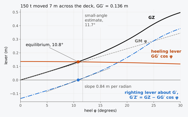
Figure 4.16 The list caused by moving 150 t 7 m across the deck of the Series 60 ship, where the heeling lever meets the righting lever computed on the heeled hull. Dash-dotted, their difference G′Z′, read against zero.
In Chapter 3 a mass of 150 t, moved 7.0 m across the midship section of this ship treated as a long prismatic body, listed the section 8.1°, less than the 10.8° of the whole hull. The prismatic body has the midship section all along its length, so its waterplane is everywhere as wide as the ship’s widest part, and its BM is 3.55 m and its GM 0.92 m, against 3.13 m and 0.66 m for the ship. The fine ends of a real hull contribute little to , because the half-breadth enters it cubed.
Subtracting the heeling lever from the righting lever gives the righting lever about G′, G′Z′ = GZ − GG′ cos φ, Z′ being the foot of the perpendicular from G′ to the vertical through ; it is drawn dash-dotted in Fig. 4.16. G′Z′ is −0.136 m upright, where the ship cannot rest, and it rises through zero at 10.8°, the angle at which the listed ship rests and about which it rolls. The slope of G′Z′ there, 0.84 m per radian on the heeled hull, is the metacentric height of the listed ship. It is larger than the 0.659 m of the upright ship, mainly because the metacentre rises as the ship heels (Sec. 4.7.5).
With GM = 0 the wall-sided cubic loses its linear term, and the list becomes . It is finite, as for a stable ship, but it varies as the cube root of the moment, and a small moment gives a large list: a shift of G of 1 cm would list a wall-sided ship with the BM of the Series 60 ship, 3.129 m, by 10.5°, against 0.9° with its GM of 0.659 m.
4.8.3 Loading to a list, and bringing a ship upright
Masses loaded or discharged off the centreline change the listing moment, as a mass moved across the ship does, and all of them are entered in the weight table at once. Taking moments, with masses loaded at , the transverse position of G becomes
a discharged mass being entered as negative. The list follows from Eq. (4.16) with , towards port when is positive. With positive to port and the heel positive with the starboard side down, the conventions used throughout, the signed list for small angles is , and G to port gives a negative heel. The weight table also gives the new KG from its vertical moments. GM changes too, through KG and, as the draught changes, through KM, and the list is found with the GM that the ship will have after the change. On board, the numerator of Eq. (4.17) is kept as a table of listing moments to port and to starboard9, as the weight table keeps the moments .
To bring a listed ship upright, the loading is chosen so that is zero: weight is moved towards the high side, loaded on the high side or discharged from the low side, in the amount that cancels the listing moment. When a load is to be shared between two positions, one on each side, Eq. (4.17) with fixes how much goes to each. The calculation is made before any weight is moved, and it is made only after the cause of the inclination is known: a ship that leans for no reason the weight table shows may be lolled, not listed, and weight moved towards the high side of a lolled ship can throw it over (Sec. 4.9.3).
Example 4.6. Loading a listed ship to bring it upright. In its departure condition the Series 60 ship, 7707 t with KG = 5.887 m and GM = 0.659 m, has 300 t of deck cargo still to come aboard, to be stowed in two stacks, one on each side, each with its centre 5.0 m from the centreline and 10.5 m above the baseline. Before the cargo is loaded the ship is seen to be listing 2.5° to starboard; soundings show that some of its fuel and water is not where its weight table assumes. (a) How should the 300 t be divided between the two stacks for the ship to finish upright? (b) Find KG, KM and GM with the cargo aboard; at 8007 t the ship floats at 6.575 m, where interpolation in the hydrostatic table gives KB = 3.531 m and the waterplane of the hull gives BM = 3.050 m. (c) If instead the whole 300 t were stacked on the port side, at what angle would the ship list?
A list can also come from a weight that is not resting on the ship’s structure. A load hanging from the ship’s own crane acts at the head of the crane from the moment it leaves the deck (Fig. 4.15(d)), and a liquid in a partly filled tank moves within the tank as the ship inclines; both are treated in Chapter 5. Flooding on one side after damage lists the ship as off-centre loading does (Chapter 12).
4.9 Negative metacentric height and the angle of loll
4.9.1 The angle of loll
The Eastland of the prologue was, in Ackerson’s reasoning, a ship with G above M. If G lies above M, GM is negative, and a small heel produces a couple that heels the ship further; the upright position is unstable. A ship with negative GM need not capsize, however. As it heels, B moves out and, for a wall-sided ship, the metacentre rises, and the righting lever of the wall-sided formula, negative at first, becomes zero again at the angle where its bracket vanishes:
This is the angle of loll10,16. At the righting lever rises through zero, as G′Z′ of the listed ship in Fig. 4.16 does at its angle of list, and the ship rests there in stable equilibrium. It may equally rest at on the other side. Differentiating the wall-sided formula at gives the slope of the curve of righting levers there, the metacentric height that the ship has in its lolled position:
which is more than twice the magnitude of the negative upright GM, because ; for a wall-sided ship the relation is exact.
Because grows as the square root of −GM, a GM only a few centimetres negative gives a loll of several degrees16; with the BM of the Series 60 ship, 3.129 m, a GM of −0.03 m gives 7.9°.
Where the lever is plotted for heels to both sides, as in Fig. 4.17(d), it is taken as a signed horizontal distance, positive when lies to starboard of G, instead of being counted positive when it rights the ship. A positive lever then turns the ship towards port and a negative lever towards starboard, whatever the heel: a ship heeled to port and being righted has a negative lever, and so has a ship with negative GM heeled slightly to starboard. On such a plot the lever rights the ship where it has the sign of the heel, and the ship can rest in stable equilibrium only where the curve rises through zero.
In Fig. 4.17 the Series 60 ship has G raised 0.80 m, and GM is negative. Heeled 8° (a), its centre of buoyancy lies on the high side of G, and the couple heels it further. As the heel grows, the waterplane widens and B moves out faster than the vertical through G, until at the angle of loll (b) lies directly under G and there is no couple. Heeled beyond it (c), lies on the low side of G, and the couple returns the ship to the angle of loll; the lolled ship is in stable equilibrium at an angle of heel. The metacentre for that angle, the centre of curvature of the path of B, lies on the vertical through G and , above G and off the centreline15. Its height above G is the slope of the righting lever there, and the point M′, where that vertical meets the centreline, coincides with G at the loll. Plotted for both sides (d), the signed lever leaves the origin with the negative slope GM, below zero to starboard and above zero to port, and rises through zero at the angle of loll on each side.
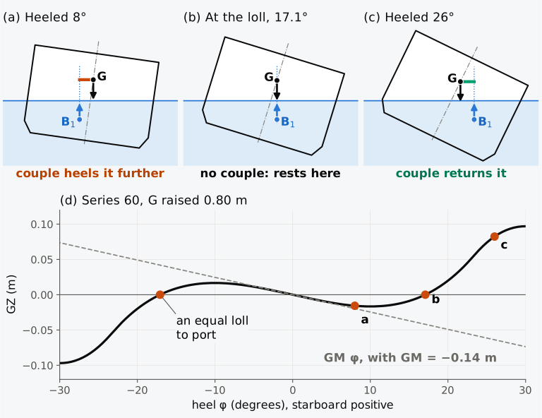
Figure 4.17 A ship with negative GM: (a) to (c) the couple below, at and beyond the angle of loll (schematic sections, moved for clarity); (d) the righting lever of the Series 60 ship with G raised 0.80 m, as a signed distance, positive with to starboard of G.
Example 4.7. An angle of loll. In its departure condition the Series 60 ship displaces 7707 t, with KG = 5.887 m, KM = 6.546 m and BM = 3.129 m. Suppose that it is loaded so that, with its displacement unchanged, G is 0.80 m higher. Find GM, and find the angle of loll and the slope of the curve of righting levers there by the wall-sided formula. Compare them with the righting lever of the whole hull.
Equation (4.18) holds only while the sides stay vertical where the water meets them. If G is raised further, to KG = 7.00 m at the displacement of the departure condition, GM becomes −0.454 m. Equation (4.18) then gives a loll of 28.3°, beyond the 22.6° at which the deck edge goes under. The righting lever of the whole hull, KN − KG sin φ, is negative at every heel up to 60°, and the ship would capsize. The lever can be written (KN/sin φ − KG) sin φ, where KN/sin φ is the height above K of the point M′ at which the vertical through meets the centreline. The lever is positive only at heels where G lies below M′. On this hull M′ reaches at most 6.89 m above the keel, at about 28°. At that displacement the ship can therefore loll only while KG lies between KM, 6.55 m, and 6.89 m.
4.9.2 Recognizing a loll
You have now met both of the steady inclinations that a ship’s own loading produces. A mass moved across the deck, or loaded off the centreline, takes G off the centreline and lists a ship whose GM is positive; when G stays on the centreline but rises above M, the ship with negative GM lolls. From the bridge the two look alike, although they differ in the ways compared in Table 4.2, and confusing them is dangerous.
Table 4.2 List and loll compared10,15.
| Feature | List | Loll |
|---|---|---|
| Cause | G off the centreline: cargo or liquid moved to one side, or weight added there | G on the centreline but above M |
| Upright reference with G on centreline | stable, GM positive | unstable, GM negative |
| Righting lever | about G′, G′Z′: upright; rises through zero at the angle of list, with a slope larger than the upright GM while the deck edge stays out of the water | about G, GZ: zero upright, with the negative slope GM; rises through zero at , with the slope |
| Side | towards the off-centre weight only | either side |
| In a seaway | rolls about the angle of list | may flop from the angle of loll on one side to an equal angle on the other |
| Remedy | weight moved or added towards the high side, or discharged from the low side, after checking GM | G lowered; no weight moved across the ship |
Kemp and Young15 describe the lolled ship as having zero GM. It is the upright ship whose GM is negative; at the angle of loll the ship has a positive metacentric height, the slope of its righting lever there.
When the weights on board are found to be evenly distributed about the centreline and the ship still lies at an angle, it is probably lolled9. A loll may also be suspected when the ship rolls with a long period, or when it flops from one side to the other. G can rise above M in service in ways that the loading plan does not show. Fuel and water consumed from double-bottom tanks remove weight from low in the ship; a timber deck cargo can take up much water in heavy weather; and ice on the weather decks of fishing vessels adds weight high up15. Free surfaces in partly filled tanks act as a rise of G. Some early double-hull tankers, with cargo tanks that spanned the ship, lolled during loading and discharge, when free surfaces in their cargo and ballast tanks acted together. The righting lever of such a ship was nearly zero between about 12° to port and 12° to starboard, and little moment was needed to roll it from one side to the other; a centreline bulkhead in the cargo tanks prevented the problem8. Ships carrying timber on deck once often left harbour with a loll10; the IS Code now requires them, when they are assessed under its alternative criteria, to keep a GM of at least 0.10 m throughout the voyage17.
4.9.3 Correcting a loll
A list is corrected by moving or adding weight towards the high side or discharging it from the low side. The Eastland’s engineers met the list in this way, letting water into the ballast tanks on the high side, and the list stopped for a time; the ship later rolled over towards the river, the side to which it had been leaning1,4. Applied to a lolled ship, the correction for a list is misleading. A small moment reduces the loll on the low side a little, while the loll that the ship would take on the other side grows and the area under its righting lever there shrinks. Beyond a certain moment the equilibrium on the low side disappears, and the ship is thrown over through the unstable upright position. The only stable equilibrium left is on the other side, at a larger angle and with less reserve against capsizing10. A bulk carrier with a cargo of iron fines developed a starboard list of more than 23° on passage; the master filled port-side ballast tanks to correct it, the ship took a large list to port, and it sank10. The account does not say whether the list came from a loll, a shift of cargo or both, but it shows the danger of a correction made on the high side.
A loll is corrected only by lowering G: by lowering weights already on board, loading weight below G, discharging weight from above G, or removing free surfaces9. In the usual procedure with water ballast, a small, subdivided double-bottom tank on the low side is filled first; once it is full, G is lower and the remaining list comes mainly from the weight being off the centreline, and the matching tank on the high side can then be filled15. While the first tank fills, the free surface of its water raises G for a time, and every change should be calculated before it is made.
Figure 4.18 compares the two orders of filling for the lolled ship and a pair of double-bottom tanks of 250 t each, 2.5 m either side of the centreline, with the free surface of the water left out. With the low-side tank filled first, the ship lists about 1° further while G falls; GM becomes positive when about 160 t is in the tank, by which point the loll has become an ordinary list, and filling the second tank brings the ship upright. With the high-side tank filled first, the water moves G towards the high side, as moved cargo would. The heel first falls, to 13.5° with 25 t in the tank, but with about 36 t the ship is thrown over to port while its GM is still negative, and the rest of the filling then brings it upright from the other side. Moving 40 t of cargo 7 m to the high side leaves the ship a single equilibrium, at 21.5° on the port side, and its range of stability on that side, the range of heel over which the lever rights it, shrinks from 24°, between 17.1° and 41.1°, to 18°, between 21.5° and 39.2°. The Eastland leaned first towards the wharf and then away from it, as a ship with negative GM may do and as Ackerson had reasoned.
These angles are equilibrium positions, found by a static calculation at each step of the filling. They give the positions in which the ship can rest and say nothing of how it moves from one position to the next. When the equilibrium on one side disappears, the ship starts to roll through the upright towards the other side, and the equilibrium there is a candidate position of rest. Whether the ship approaches it gently or rolls past it first depends on its inertia in roll and on the damping of the water, which the static calculation leaves out. If it rolls past, and its range of stability on that side is small, the motion can carry it beyond the angle at which its righting lever vanishes. Here “thrown over” means only that the static equilibrium on the first side has gone and the only equilibrium left is on the other side.
For this pair of low tanks in the illustrative calculation, filling the low side first keeps the ship at rest on the side to which it already leans, and its heel falls to zero without the ship being thrown over to the other side. This result is not a general instruction to ballast a ship whose inclination is unexplained. The cause, remaining freeboard, downflooding openings and free-surface effects must be checked before choosing a correction.
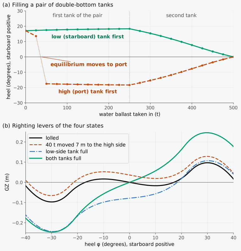
Figure 4.18 Correcting the loll of the Series 60 ship with G raised 0.80 m: (a) the heel as a pair of double-bottom tanks of 250 t each is filled, in either order; (b) the righting levers of four states. The free surface of the water is left out.
Example 4.8. Correcting the loll. The Series 60 ship, 7707 t with KG = 6.687 m, GM = −0.141 m and BM = 3.129 m, lies at its angle of loll to starboard. (a) It is proposed to move 40 t of cargo 7.0 m to port, the high side. Where would its equilibrium then be, by the wall-sided formula? (b) Instead, a pair of double-bottom tanks is filled with sea water, 250 t in each, with their centres 0.75 m above the keel and 2.5 m either side of the centreline, the starboard tank first. Interpolation in the hydrostatic table gives KB = 3.512 m at 7957 t and 3.607 m at 8207 t, and the waterplanes of the hull give BM = 3.063 m and 3.001 m. Find KG and GM with the starboard tank full, and the list then, and KG and GM with both full. Leave out the free surface of the water while each tank fills.
4.9.4 Exploring the righting lever
Explorer 4.1 draws the righting lever of two hulls, a long box of the barge’s section and the Series 60 ship at the displacement of its departure condition, for any heel and any height of G. The computed GZ is drawn with GM sin φ and the wall-sided formula, beside the section with B, G and Z at the chosen angle. Raise G until GM is negative to find the angle of loll, and raise it further to find a ship whose righting lever does not become positive again up to 50°, the end of the plot.
4.9.5 Initial stability, heel and loll (Calculator 4.1)
Calculator 4.1 applies the relations of Secs. 4.4 to 4.9 to a ship given by its displacement, KB, BM and KG, and shows its working in steps, as a worked example does. It finds the metacentric height first and then, if a heel is given, the righting lever and moment at that heel, both for small angles and with the wall-sided formula. If a mass moved across the deck is given, it finds the heel this causes and, for a ship with negative GM, the side and the angle of its possible equilibrium within the wall-sided assumptions. When GM is negative, its last step is the angle of loll.
Choose one of the worked examples or exercises to load its numbers. Its question appears above the inputs, and it changes as you change the numbers, so the working always answers the question shown. The calculator also tells you when a result needs further assessment: a metacentric height below the general 0.15 m minimum in the IS Code (the ship-specific requirements may differ), a heel at which the small-angle and wall-sided results differ by more than 5 %, or, if you give the breadth with the freeboard or the draught, a heel at which the deck edge goes under or the bottom comes out of the water.
4.10 The longitudinal metacentre
4.10.1 The longitudinal metacentric radius
Everything so far has concerned heel. A small change of trim, the other inclination, can be treated with wedges as a small heel was (Fig. 4.19(a)), and the result is used in Chapter 6 to find the draughts of a loaded ship. Trim the ship through a small angle at constant displacement: the waterline moves from WL to , a wedge of the hull goes under at one end and a wedge comes out at the other. Let the waterplane turn about a transverse axis at . A strip of the waterplane of length and half-breadth , at a distance from that axis, adds or removes a volume . The two wedges have equal volumes, as constant displacement requires, only if , that is, only if and the axis passes through the centroid of the waterplane, the centre of flotation F. A ship trims about F for this reason16. The moment of the moved volume about the transverse axis through F is
where is the longitudinal second moment of the waterplane about that axis, found from the second moment about the AP by the parallel-axis theorem. B therefore moves along the ship through , and, as for a heel, the verticals through B and meet at the longitudinal metacentre , at a height above B of
the longitudinal metacentric radius. The longitudinal metacentre lies at , and the longitudinal metacentric height is
For a box, , and the ratio of the two radii is . For the Wigley hull (Exercise 4.12), the coefficient that Attwood14 quoted from White as a rough approximation, with many exceptions; the Series 60 hull gives 0.059. The longitudinal radius is of the order of the ship’s length, and so many times larger than BG that the approximation is close.
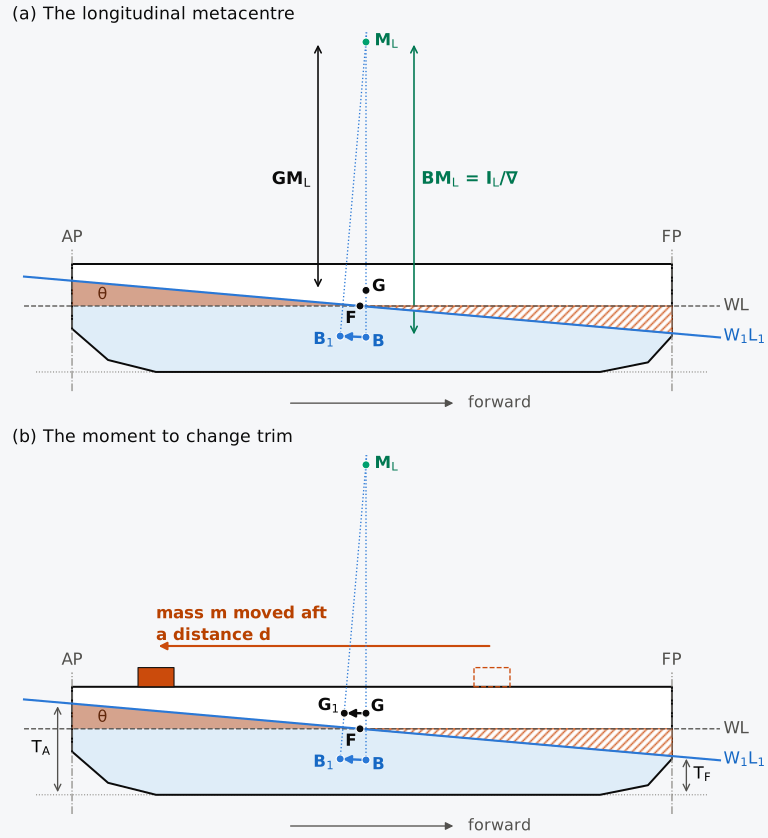
Figure 4.19 (a) The longitudinal metacentre, for a small trim by the stern; (b) the moment to change trim, for a mass moved aft. Schematic, trim and heights not to scale; immersed wedge shaded, emerged wedge hatched.
4.10.2 The moment to change trim one centimetre
The longitudinal metacentric height gives the moment needed to change the trim. Start from even keel and move a mass a distance aft (Fig. 4.19(b)). As for a mass moved across the ship, taking moments shows that G moves parallel to the movement through , and the ship trims until lies under . For a small trim the vertical through and passes through , so that
The ship now trims by the stern by , and the tangent of the trim angle is the trim divided by the distance between the perpendiculars at which the draughts are taken, . Equating the two gives, for the trim , the trimming moment16
The relation also holds for a mass moved forward, which trims the ship by the head. For a trim of one centimetre, = 0.01 m, and the moment to change trim one centimetre is
in t·m per cm when is in tonnes and the lengths in metres8; like the moment of statical stability, it is a moment of mass. Because is close to and , replacing by gives
which depends only on the waterplane and not on the position of G, and it can be tabulated with the hydrostatic curves before the loading is known8. It differs from Eq. (4.22) by the ratio : it is slightly larger when G is above B, as in almost every ship, and slightly smaller in the rare case of G below B.
Example 4.9. The longitudinal metacentre of the Series 60 ship. In its departure condition the Series 60 ship, 121.92 m between perpendiculars and 16.256 m wide, displaces 7707 t, or 7519.0 m³, with KB = 3.417 m and KG = 5.887 m. Its waterplane has an area of 1394.7 m², its centre of flotation is 56.43 m forward of the AP, and its second moment is m⁴ about the transverse axis through F and 23,528 m⁴ about the centreline. Find , and MCT 1 cm, estimate MCT 1 cm from the second moment of the waterplane alone, and compare the longitudinal and transverse second moments.
Usually it is transverse stability that matters. A ship of ordinary proportions, much longer than it is wide, has a longitudinal metacentric height of the order of its length, 135 m for the Series 60 ship, and G would have to rise far above any deck to come near . Its transverse GM is a fraction of a metre, of the order of the shifts of G that loading, consumption and moving masses produce. The longitudinal criterion has the form of the transverse criterion, , and a body that is short for its height, or a body with its weights very high, can fail it. A ship usually comes near it only when much of its waterplane is lost, as when a compartment at one end floods (Chapter 12). A submerged submarine, which has no waterplane, has its two metacentres at B, with GM equal to BG for inclinations about either horizontal axis8.
4.11 Initial stability in practice today
You have found GM from the hull and the loading and judged it by its sign, by the roll period it gives and by how far GM sin φ holds. An officer meets it as a number to be checked against a rule, with a computer to do the arithmetic. This section describes that practice as of 2026 and is revised at each release of the book.
4.11.1 Minimum metacentric height in the rules
The IS Code20, adopted by Resolution MSC.267(85), requires, among its general criteria for passenger and cargo ships of 24 m and over17, that the initial metacentric height be not less than 0.15 m. Part A of the Code is mandatory17,21 for ships of 24 m and over built on or after 1 July 2010, through SOLAS regulation II-1/5.1 and the 1988 Load Lines Protocol, as amended by Resolutions MSC.269(85) and MSC.270(85). Under the IS Code, the metacentric height in these criteria is corrected for the free surfaces of liquids in tanks in every loading condition17, by the method of Part B, 3.1, which Chapter 5 follows. Other values apply to particular ships: at least 0.10 m at all times on a voyage for ships carrying timber deck cargoes under the alternative criteria (Part A, 3.3.2.3), and 0.35 m recommended for single-deck fishing vessels (Part B, 2.1.3.1). The Code’s Explanatory Notes, MSC.1/Circ.1281, trace its general criteria to those adopted in 1968, which were derived from statistical analyses of ships that had capsized and ships that had operated safely17; they do not explain how the particular value of 0.15 m was chosen.
Two of the passenger ship criteria limit the heel caused by a heeling moment. Under the IS Code, the heel caused by passengers crowding to one side must not exceed 10°, with each passenger taken as at least 75 kg, standing passengers with their centre of gravity 1 m above the deck, and a density of four persons per square metre that need not be exceeded. The heel caused by turning must not exceed 10° either, under the heeling moment in kN·m, with the service speed in m/s, the displacement mass in tonnes and the mean draught in metres17. The Code writes , and for , and . Chapter 9 applies both criteria. The Code also recommends, without requiring it, that a timber deck cargo ship’s GM should preferably not exceed 3 % of its breadth (Part B, 3.7.5), an upper limit for a case where too much stability is the hazard. Part B, 5.1.6 notes that the criteria of Part A, chapter 2 set minimum values and no maximum, and advises that excessive GM be avoided because of the accelerations it causes.
4.11.2 Limiting curves and stability instruments
A master does not compute GM from first principles. SOLAS21 requires the stability information supplied to the master to include curves or tables of minimum operational GM against draught, or the equivalent curves of maximum allowable KG, that ensure compliance with the intact and damage stability requirements over the full range of operating draughts and trims. The IS Code requires such curves, where they are used to show compliance with its intact stability criteria, to cover the full range of operational trims, unless the Administration agrees that the effect of trim is not significant17. The officer computes KG from the loading and compares it with the curve. The two forms of curve are not interchangeable without care. The UK Maritime and Coastguard Agency’s Marine Guidance Note MGN 611(M) points out that, because KM varies with draught and trim, a curve of limiting KG and a curve of limiting GM may not be exactly equivalent22; the trimmed arrival condition of the Series 60 ship showed this effect.
Where the calculation is made with a stability instrument, a loading computer, the IS Code expects the values it presents to include VCG and VCB, the vertical centres of gravity and buoyancy, that is KG and KB17. The Code treats the instrument as a supplement to the stability booklet, in which the approved stability information is supplied to the master, and not as a substitute for it17. The classification societies’ unified requirement for such software, IACS UR L5 (Rev. 4, 2020), defines four types, from a type that computes intact stability only to a type that computes the damage stability of the actual loading condition with an actual flooding case. For approval on a ship, the transverse GM that the instrument computes, both solid and corrected for free surfaces, must agree with the approved stability information to within 1 % of the approved value or 5 cm, whichever is greater23.
4.11.3 Casualties with an incorrect metacentric height
Accident investigations show how the check fails in service. The car carrier Golden Ray capsized while turning in St. Simons Sound, outbound from Brunswick, Georgia, on 8 September 2019. The United States National Transportation Safety Board determined that the probable cause was the chief officer’s error in entering ballast quantities into the stability program, which led him to misjudge the ship’s stability and left the vessel with too small a righting lever to counteract the forces developed in the turn24. He had calculated a GM of 2.45 m; the Coast Guard’s Marine Safety Center put the GM on the voyage at about 1.76 m, below both that value and the minimum of 2.54 m required by the ship’s trim and stability booklet24. The car carrier Hoegh Osaka took a heavy list in the Solent on 3 January 2015 and was grounded on the Bramble Bank. The Marine Accident Investigation Branch could not determine the GM on departure. Recreating the condition that the chief officer had probably used, with the vertical centres of gravity of the cargo left at deck level by default, gave a GM of 1.29 m against a required minimum of 1.34 m; with the actual ballast and cargo heights the GM was lower still, and with about 0.7 m the Branch reproduced the ship’s behaviour in the turn25.
Too much GM is also a hazard. The container ship MSC Zoe lost containers overboard in the North Sea on 1–2 January 2019 while sailing with a solid GM of 10.23 m, 9.01 m after the free surface correction, against a cargo securing manual whose lashing system was designed for a GM of 2.08 m or less26. A large GM gives a short natural roll period and, for a given angle of roll, large accelerations. The opposite extreme appeared on the Maersk Essen, which lost containers in the North Pacific on 16 January 2021 with a GM of 0.92 m and a natural roll period of about 40 s. The Danish investigators found that, in the waves the ship met, this combination most likely brought on parametric roll resonance27. In parametric roll the metacentric height rises and falls as each wave passes along the hull, and the ship is alternately stiff and tender; the roll can build up when the ship meets the waves at half its natural roll period27. IMO’s interim guidelines on the second generation intact stability criteria (MSC.1/Circ.1627, December 2020) include an assessment of excessive lateral acceleration, applied when the metacentric height exceeds 8 % of the breadth and the highest place where people may be is more than 70 % of the breadth above the waterline28. The guidelines were approved for trial use; submissions to IMO since have reported experience of that use29, and the sources consulted for this section show no decision, by November 2026, to make them mandatory.
4.12 From initial stability to moving loads
You can now take the Series 60 ship, or any ship whose KB, BM and KG are known, and say whether it stands upright and how far a small moment heels it. The hull gives KB and BM, from the waterplane and the volume below it, and the loading gives KG; the metacentric height combines them in one number. For small angles, GM gives the righting lever and the heel caused by a small moment, and its sign determines whether the upright ship is stable. How far the small-angle results hold can be judged from the ratio BM/GM or, better, by computing the righting lever of the heeled hull.
So far the weights have been fixed in the ship, and in Chapter 5 they move. A mass moved on board moves G, as in Sec. 4.8. A suspended load acts at its point of suspension, and lifting it raises G at once. A bulk cargo such as grain can slide to the low side in a heavy roll and stay there. The free surface of a liquid in a partly filled tank moves its centre of gravity as the ship heels, and this has the effect of reducing GM, as it does for a time while a tank is filled to correct a loll. On the Eastland, the weights changed in several ways on the morning of the disaster: two ballast tanks were emptied, 2,500 passengers came aboard, and the engineers let water into the tanks on the high side when the ship listed. In Chapter 6 the longitudinal metacentre and the moment to change trim give the draughts of a loaded ship, and in Chapter 7 KB, KM, and MCT 1 cm are tabulated against draught. Chapter 8 follows the righting lever to large angles with Atwood’s formula, named after the mathematician George Atwood, not the Attwood of the textbook cited in this chapter. There the hull’s part of the lever, KN, is no longer KM sin φ; it is computed on the heeled hull and tabulated against the heel and the displacement as the cross curves of stability.
Summary
A small heel moves a wedge of the hull out of the water on one side and an equal wedge into it on the other, and the centre of buoyancy moves towards the low side by . The vertical through the new centre of buoyancy crosses the centreline at the metacentre M, at a height BM = above B, which depends only on the hull and the draught. For hulls of the same shape, BM grows with the square of the breadth and falls with the draught.
The metacentric height GM = KB + BM − KG combines that geometry with the height of G from the weight table. For small angles the righting lever is GM sin φ, the hull’s part KN = KM sin φ less the loading’s part KG sin φ, and GM sets the natural period of a small, undamped roll; for a given radius of gyration the period varies inversely as the square root of GM.
For a ship with vertical sides at the waterline, B also rises as it moves out, and the wall-sided formula corrects GM sin φ, by a fraction that grows as , until the deck edge goes under or the bilge comes out.
A mass moved across the ship, or loaded off the centreline, moves G across and lists the ship; at small angles the tangent of the list is the shift of G divided by GM. The ship is brought upright by a loading that returns G to the centreline.
A ship with negative GM is unstable upright; it may loll to one side or the other, resting where its lever rises through zero as a listed ship does, or capsize if its righting lever never becomes positive again. A loll differs from a list in its cause and its remedy; it is removed only by lowering G, and moving more than a little weight towards the high side leaves the ship only an equilibrium on the other side, at a larger angle.
The longitudinal metacentre, which gives the moment to change trim one centimetre, is of the order of the ship’s length above B, and it is usually transverse stability that limits a ship. On board, these results are applied as working rules:
- compute BM from the second moment of the waterplane, and KG from the weight table, and take GM as the difference of KM and KG;
- treat the water ballast as part of the stability: emptying a double-bottom tank raises G, and a partly filled tank reduces GM;
- treat GM sin φ as a small-angle approximation, and check how far it holds from BM/GM or from the computed righting lever;
- read a lengthening roll period as a sign of falling GM;
- find the cause of a list in the weight table before correcting it, and correct it with a loading that brings G back to the centreline, calculated with the GM the ship will have afterwards;
- correct a loll by lowering G, never by moving weight across the ship, filling a low-side tank before its high-side pair in the example considered here; establish the cause and calculate free-surface and flooding effects before choosing a sequence for a real ship;
- use KM for the actual waterline, trimmed if the ship is trimmed, and the GM corrected for free surface.
Notes on the data
Series 60. Values for the Series 60 hull are computed from the hull surface of Sec. 1.5.5, a bare moulded hull with its deck at 1.5 times the design draught and no superstructure. The heeled calculations of this chapter hold the displacement constant and the trim at zero; righting levers for approval are computed with the ship free to trim (Chapter 8).
Loading conditions. The departure and arrival conditions of Table 3.1 are illustrative, and so is the raised G of Example 4.7. Their metacentric heights are solid values, before the free surface correction, and G is taken on the centreline; the of 7 mm in the departure condition would list the ship by about 0.6°. The roll periods are estimates by the IS Code’s formula, not computed from a distribution of mass. The tanks of Example 4.8 and Fig. 4.18 are illustrative, and the free surface of the water while they fill is left out.
The Eastland. No measured metacentric height of the ship in 1915 has been found; Fig. 4.1 is a schematic of the reasoning given at the inquiry, not a calculation for the ship.
Regulations. The IS Code and SOLAS are summarized here from their consolidated texts17,21 for teaching. For a real ship, the texts in force and the Administration’s interpretation of them govern.
Exercises
Under each exercise, “Show answers” opens its short answers and “Show full solution” its worked solution. The exercises marked as adapted come from Attwood14 (public domain). Use = 1.025 t/m³ for sea water, 1.000 t/m³ for fresh water and = 9.81 m/s².
4.1 A box barge 61.0 m long and 9.15 m wide floats in sea water with a displacement mass of 2030 t. Find its draught and the height of its metacentre above the keel. Adapted from Attwood14.
4.2 Show that the metacentre of a box of breadth lies above the waterline when the draught is less than and below it when the draught is greater. Find that draught for a box 3.66 m wide. Adapted from Attwood14.
4.3 A raft is made of two circular cylinders 1.52 m in diameter, with their axes 3.05 m apart, floating with their axes in the surface. Find its metacentric radius. Find it again for three such cylinders spread equally across an overall breadth of 7.62 m. Adapted from Attwood14.
4.4 A homogeneous log of square section, 0.61 m by 0.61 m and 3.66 m long, of relative density 0.5, floats in fresh water. Show that it cannot float stably with two faces horizontal. Find its transverse metacentric height when it floats with a diagonal of its section vertical, and its longitudinal metacentric height. Adapted from Attwood14.
4.5 A long body of square section, side , has its centre of gravity at the centre of the section and floats with two faces horizontal. Show that it is stable for draughts less than and greater than , and unstable between. Adapted from Attwood14.
4.6 For a long body of constant section, BM , where is the waterline breadth. Find and KB/T for a rectangle; an isosceles triangle with its apex down; a section whose upper half is a rectangle and lower half a triangle; and a section whose half-breadth varies as the square root of the height above the keel. Adapted from Attwood14, extended.
4.7 A vessel has rectangular sections throughout its length. At a draught of 3.05 m the half-breadths of its waterplane, at stations 6.10 m apart, are 0.15, 1.83, 3.66, 4.88, 4.57, 2.74 and 0 m. Its centre of gravity is in the waterplane. Find its metacentric height, using Simpson’s rule. Adapted from Attwood14.
4.8 A solid vertical cylinder of radius floats upright at a draught with its centre of gravity in the waterplane. Show that its upright GM is positive only if . Discuss the limiting case. Adapted from Attwood14.
4.9 A stern-wheel river steamer is treated as a box 36.6 m long and 6.10 m wide, floating in sea water at a draught of 0.457 m, with its centre of gravity 2.44 m above the waterline. Find its transverse and longitudinal metacentric heights and its MCT 1 cm. Adapted from Attwood14.
4.10 A circular pontoon 15.2 m long and 4.88 m in diameter floats in sea water with its axis in the surface; its centre of gravity is 1.22 m above the bottom. Find its transverse metacentric height and the list when a mass of 10 t is moved 0.91 m across it. Find its longitudinal metacentric height. Adapted from Attwood14.
4.11 A ship of 4060 t has a metacentric height of 0.76 m. Its crane lifts 102 t of cargo and lands it 5.5 m to starboard of where it was and 1.4 m higher. Find the list. How large would it be if the cargo had been landed 1.4 m lower? Adapted from Attwood14.
4.12 The Wigley hull has half-breadths , with and , below its design waterline. Show that at the design draught , KB , BM and , and evaluate them for = 100 m, = 10 m and = 6.25 m.
4.13 In its arrival condition the Series 60 ship displaces 7236 t with KG = 6.129 m and floats at an even-keel draught of 6.034 m, where KB = 3.235 m and BM = 3.262 m. Find GM. In the departure condition KG = 5.887 m and KM = 6.546 m; find how much of the fall of GM between the two conditions comes from the rise of G and how much from the fall of M. Solved on the hull, the arrival condition trims 0.77 m by the head, and at that waterline KM = 6.464 m. Find the GM of the trimmed ship.
4.14 The Series 60 ship, 7707 t with KG = 5.887 m in its departure condition, is to carry 400 passengers on its weather deck. Taking 75 kg each, with their centre of gravity 1 m above the deck at 9.754 m, find the new KG and, with KM = 6.549 m at the new draught of 6.388 m, computed on the hull, the new GM. Find the list if all of them move 6.0 m towards one side.
4.15 A ship has KB = 3.42 m and BM = 3.13 m, and its sides are vertical near the waterline. A change of loading raises KG to 6.69 m. Find GM, the angle of loll and the slope of the curve of righting levers at that angle.
4.16 For a rectangular waterplane of length and breadth , show that . In its departure condition the Series 60 ship, 121.92 m between perpendiculars and 16.256 m wide, displaces 7519.0 m³, and its waterplane has m⁴ about the transverse axis through F and = 23,528 m⁴. Find the ratio for the ship, and explain the difference. Find , with the length between perpendiculars.
4.17 In its arrival condition the Series 60 ship, 16.256 m wide, floats at an even-keel draught of 6.034 m with a waterline 122.84 m long and GM = 0.368 m. Estimate its natural roll period by the IS Code’s formula, and find Kempf’s factor. What would the period be if the free surfaces of its partly filled tanks reduced GM to 0.30 m?
4.18 A box barge 60 m long and 12 m wide floats in sea water at an even-keel draught of 3.0 m with KG = 4.0 m. Find , and MCT 1 cm, and estimate MCT 1 cm from the second moment of the waterplane alone. A mass of 20 t on its deck is moved 30 m aft; find the change of trim.
4.19 A ship of 6000 t lies at about 6° to port in calm water, although no weight on board has been moved to port. At this displacement its stability information gives KM = 7.20 m and BM = 3.60 m, and the loading gives KG = 7.22 m with G on the centreline; take its sides as vertical near the waterline. (a) Is the ship listed or lolled? Find the angle that the wall-sided formula predicts. (b) Where would its equilibrium be if 30 t of cargo were moved 8.0 m to starboard? (c) A double-bottom tank of 100 t is available on each side, with its centre 0.6 m above the keel. Taking KM and BM as unchanged, find GM with the port tank full and with both full, and say in which order the tanks should be filled.
4.20 A ship of displacement mass 5200 t has KM = 7.10 m and KG = 6.45 m and floats upright. (a) In one hold, 40 t of cargo is restowed from 4.2 m to port of the centreline to 3.8 m to starboard of it, at its original height. Find the list. (b) How much ballast must then be pumped from the starboard double-bottom tank to the matching port tank, their centres 3.0 m either side of the centreline at equal heights, for the ship to be upright again?
4.21 A ship of displacement mass 9600 t has GM = 0.55 m. In heavy weather 120 t of cargo shifts, its centre of gravity moving 5.5 m to starboard and 1.2 m upwards. Find the GM after the shift and the list.
4.22 A box barge 60 m long, 12 m wide and 6 m deep floats in sea water at an even-keel draught of 3.0 m with KG = 4.0 m. A mass of 50 t on its deck is moved 8.0 m to starboard at its own height. The sides of the barge stay vertical where the water meets them up to a heel of 26.6°, so the wall-sided formula is exact. Tabulate the righting lever about G′, , at 0°, 2°, 4°, 6°, 8° and 10°, plot it and read off the list. Compare the list with that given by Eq. (4.16), and estimate the slope of the curve at the list.
Symbols introduced in this chapter
| Symbol | Meaning | Unit |
|---|---|---|
| coefficient in BM ; for a ship | – | |
| centre of buoyancy of the heeled ship | – | |
| BM | transverse metacentric radius | m |
| longitudinal metacentric radius | m | |
| coefficient of the IS Code’s estimate of the roll period | – | |
| distance through which a mass is moved | m | |
| , | centroids of the emerged and immersed wedges | – |
| G′, Z′, G′Z′ | centre of gravity off the centreline, the foot of the perpendicular from it to the vertical through , and the righting lever about it | –, –, m |
| GG′, | shift of the centre of gravity across and along the ship | m |
| GM | transverse metacentric height; in the IS Code | m |
| longitudinal metacentric height | m | |
| radius of gyration (gyradius) in roll | m | |
| KM, | heights of M and above the keel | m |
| KN | horizontal distance from the keel point K to the vertical through | m |
| M, | transverse and longitudinal metacentres | – |
| M′ | point where the vertical through meets the centreline | – |
| heeling moment | kN·m | |
| a mass moved on board | t | |
| MCT 1 cm | moment to change trim one centimetre | t·m/cm |
| N | foot of the perpendicular from K to the vertical through | – |
| natural period of roll | s | |
| volume of one wedge | m³ | |
| a small change of the angle of heel | rad | |
| angle of loll | rad or ° |
Corrections
Corrections to version 1.0, released on 3 November 2026, with their dates.
- 3 November 2026. Example 4.6 gives the two stacks of deck cargo to 0.01 t, 172.17 t and 127.83 t, so that their difference, 44.34 t, follows from the printed values.
- 3 November 2026. Secs. 4.11.1 and 4.11.2, the Notes on the data and the reference list cite SOLAS in its consolidated edition of 2024, in place of that of 2020.
- 3 November 2026. Sec. 4.6 cites the IS Code’s recommendations on ice formation as Part B, Annex 2.
- 5 November 2026. The route for a first reading keeps the opening of Sec. 4.7.5, on the metacentre at a heel of any size, which Secs. 4.8.2 and 4.9.1 and Chapter 8 use.
- 5 November 2026. Sec. 4.1.2 refers to Sec. 1.3.2 for the different usages of heel and list instead of repeating them, and Secs. 4.1.2 and 4.1.3 no longer set in bold the terms defined in Chapter 1.
- 5 November 2026. The prologue converts the 225 to 250 tons of tank No. 3 for short and for long tons. Sec. 4.12 says that Atwood’s formula is named after George Atwood, not the Attwood of the textbook, and no longer calls the GM reduced by a free surface the effective GM.
- 5 November 2026. Sec. 4.11.2 states the tolerance of IACS UR L5 on GM as 1 % of the approved value or 5 cm, whichever is greater.
References
- Estep, H. C. (1915, September). [Article on the capsizing of the Eastland and the investigations]. Marine Review, 320–327. https://images.maritimehistoryofthegreatlakes.ca/126818/page/4 Cited: ↑ p. 320 · ↑ p. 320 · ↑ p. 321 · ↑ pp. 323–324 · ↑ p. 320 · ↑ pp. 321, 324 · ↑ p. 323 · ↑ pp. 321, 323–324
- Naval History and Heritage Command. (n.d.). Wilmette (gunboat). In Dictionary of American naval fighting ships. Retrieved October 8, 2026, from https://www.history.navy.mil/content/history/nhhc/research/histories/ship-histories/danfs/w/wilmette.html Cited: ↑ · ↑
- House Committee on the Merchant Marine and Fisheries. (1916). Investigation of accident to the steamer “Eastland,” Chicago, Ill., July 24 to August 5, 1915: Copy of testimony and report of board of inquiry made to Secretary of Commerce (64th Cong., 1st sess.). Government Printing Office. https://archive.org/details/investigation-of-accident-to-the-steamer Cited: ↑ pp. 15–16, 19–20, 126–127 · ↑ pp. 135–138 · ↑ p. 178 · ↑ pp. 229–230 · ↑ pp. 311–316 · ↑ p. 342
- Stranahan, S. Q. (2014, October 27). The Eastland disaster killed more passengers than the Titanic and the Lusitania. Why has it been forgotten? Smithsonian Magazine. https://www.smithsonianmag.com/history/eastland-disaster-killed-more-passengers-titanic-and-lusitania-why-has-it-been-forgotten-180953146/ Cited: ↑ · ↑ · ↑ · ↑
- Newberry Library. (2019, August 13). The Newberry to receive collection from Eastland Disaster Historical Society. https://www.newberry.org/news/the-newberry-to-receive-collection-from-eastland-disaster-historical-society Cited: ↑
- Eastland Disaster Relief Committee. (1918). Eastland disaster relief: After the capsizing of the steamer “Eastland” in the Chicago River, July 24, 1915, to completion of relief work. Final report. Chicago Chapter, American Red Cross. https://librarycollections.law.umn.edu/documents/archive/darrow/Eastland%20red%20cross.pdf Cited: ↑ p. 9
- In re St. Joseph-Chicago S.S. Co., 78 F.2d 984 (7th Cir. 1935). https://librarycollections.law.umn.edu/documents/archive/darrow/%21935%20Eastland%20case.pdf Cited: ↑ · ↑
- Moore, C. S. (2010). Intact stability (J. R. Paulling, Ed.; Principles of Naval Architecture Series). Society of Naval Architects and Marine Engineers. Cited: ↑ p. 1 · ↑ p. 24 · ↑ p. 22 · ↑ p. 14 · ↑ p. 8 · ↑ p. 16 · ↑ p. 11 · ↑ p. 22 · ↑ pp. 6–8 · ↑ p. 14 · ↑ pp. 35–36 · ↑ p. 14 · ↑ p. 14 · ↑ p. 14
- Barrass, C. B., & Derrett, D. R. (2006). Ship stability for masters and mates (6th ed.). Butterworth-Heinemann. Cited: ↑ p. 44 · ↑ p. 47 · ↑ p. 46 · ↑ pp. 104–106 · ↑ p. 50 · ↑ pp. 356–359 · ↑ p. 359 · ↑ pp. 48–49 · ↑ p. 45 · ↑ p. 47 · ↑ p. 124 · ↑ pp. 126–127 · ↑ p. 53 · ↑ p. 48
- Biran, A., & López-Pulido, R. (2014). Ship hydrostatics and stability (2nd ed.). Butterworth-Heinemann. Cited: ↑ pp. 42–45 · ↑ pp. 45–46 · ↑ pp. 47–49 · ↑ p. 118 · ↑ pp. 40–41 · ↑ p. 141 · ↑ pp. 139–141 · ↑ p. 139 · ↑ p. 141 · ↑ p. 141 · ↑ p. 119 · ↑ p. 48 · ↑ pp. 47–49 · ↑ pp. 60–61 · ↑ p. 139 · ↑ pp. 153–158 · ↑ p. 154 · ↑ p. 156 · ↑ pp. 154–156 · ↑ p. 156
- ITTC. (2024). ITTC dictionary of hydromechanics (Version 2024). International Towing Tank Conference. Cited: ↑ s.v. "metacentre" · ↑ s.v. "metacentric radius" · ↑ s.v. "metacentre height"
- Bouguer, P. (1746). Traité du navire, de sa construction, et de ses mouvemens. Ch. Ant. Jombert. Cited: ↑
- Nowacki, H., & Ferreiro, L. D. (2003). Historical roots of the theory of hydrostatic stability of ships. In Proceedings of the 8th International Conference on the Stability of Ships and Ocean Vehicles (STAB 2003) (pp. 1–30). Escuela Técnica Superior de Ingenieros Navales. https://shipstab.org/files/Proceedings/STAB/STAB2003/Papers/Paper%2001.pdf Cited: ↑ p. 10 · ↑ p. 12 · ↑ pp. 17–18 · ↑ p. 24 · ↑ p. 6
- Attwood, E. L. (1899). Text-book of theoretical naval architecture. Longmans, Green, and Co. (Public domain.) Cited: ↑ p. 107 · ↑ pp. 109–110 · ↑ pp. 160–162 · ↑ pp. 160–162 · ↑ pp. 160–162 · ↑ p. 161 · ↑ p. 139 · ↑ · ↑ ch. III, Ex. 23 · ↑ ch. III, Ex. 24 · ↑ ch. III, pp. 106–107 · ↑ ch. III, pp. 108–109 and Ex. 8, and ch. IV, Ex. 17 · ↑ ch. III, Ex. 26 · ↑ ch. III, Ex. 30 · ↑ ch. III, Ex. 7 · ↑ ch. III, Ex. 34 · ↑ ch. IV, Ex. 4 · ↑ ch. IV, Ex. 7 · ↑ appendix, p. 277
- Kemp, J. F., & Young, P. (2001). Ship stability: Notes and examples (3rd ed., rev. C. B. Barrass). Butterworth-Heinemann. Cited: ↑ p. 58 · ↑ p. 53 · ↑ p. 64 · ↑ pp. 63–64, 133–134 · ↑ p. 133 · ↑ p. 65 · ↑ pp. 65–66
- Tupper, E. C. (2013). Introduction to naval architecture (5th ed.). Butterworth-Heinemann. Cited: ↑ pp. 54–55 · ↑ p. 62 · ↑ pp. 67–68 · ↑ p. 74 · ↑ p. 68 · ↑ pp. 74–76 · ↑ p. 75 · ↑ p. 55 · ↑ p. 56
- IMO. (2020a). International Code on Intact Stability, 2008 (2020 ed.). International Maritime Organization. (Includes the Explanatory Notes, MSC.1/Circ.1281.) Cited: ↑ Part A, 2.3.4 · ↑ Part B, Annex 2, 3.3.4 · ↑ Part A, 3.3.2.3 · ↑ Part A, 2.2.4 · ↑ MSC.267(85), preamble · ↑ Part A, 2.1.2 · ↑ pp. 140–145 · ↑ Part A, 3.1.1 and 3.1.2 · ↑ Part A, 2.1.7 · ↑ Part B, 4.1.4.1 · ↑ Part B, 4.1.1.2 · ↑
- Fuller, H. J. (2025). “The whole history of this ill-fated vessel”: HMS Captain, the American Civil War, and the mid-Victorian struggle for naval superiority. International Journal of Naval History, 18(1). https://ijnh.seahistory.org/the-whole-history-of-this-ill-fated-vessel-hms-captain-the-american-civil-war-and-the-mid-victorian-struggle-for-naval-superiority/ Cited: ↑ · ↑
- UK Parliament. (1871, June 16). Her Majesty’s ship “Captain”: Observations (HL Deb vol. 207, cols. 122–135). Hansard. https://api.parliament.uk/historic-hansard/lords/1871/jun/16/observations Cited: ↑ col. 123
- IMO. (2008). Adoption of the International Code on Intact Stability, 2008 (2008 IS Code) (Resolution MSC.267(85), adopted 4 December 2008). International Maritime Organization. Retrieved October 9, 2026, from https://wwwcdn.imo.org/localresources/en/KnowledgeCentre/IndexofIMOResolutions/MSCResolutions/MSC.267(85).pdf Cited: ↑
- IMO. (2024). SOLAS: Consolidated edition 2024 (Sales No. IH110E). International Maritime Organization. Cited: ↑ · ↑ reg. II-1/5-1 · ↑
- Maritime and Coastguard Agency. (2019). Damage stability: Alternative verification method for tankers – UK interpretations and procedures (MGN 611(M)). Retrieved October 8, 2026, from https://assets.publishing.service.gov.uk/media/5d303f1ae5274a14f41d28a1/MGN611.pdf Cited: ↑ p. 5
- IACS. (2020). Computer software for onboard stability calculations (UR L5, Rev. 4, June 2020). International Association of Classification Societies. Retrieved October 9, 2026, from https://iacs.s3.af-south-1.amazonaws.com/wp-content/uploads/2022/02/17101147/ur-l5rev4.pdf Cited: ↑ Sections 3 and 5.2, Table 1 and Note 2
- NTSB. (2021). Capsizing of roll-on/roll-off vehicle carrier Golden Ray, St. Simons Sound, Brunswick, Georgia, September 8, 2019 (Marine Accident Report NTSB/MAR-21/03). National Transportation Safety Board. Retrieved October 8, 2026, from https://www.ntsb.gov/investigations/AccidentReports/Reports/MAR2103.pdf Cited: ↑ p. v · ↑ Sections 1.7.3 and 1.8.3
- MAIB. (2016). Report on the investigation into the listing, flooding and grounding of Hoegh Osaka, Bramble Bank, The Solent, UK on 3 January 2015 (Report No. 6/2016). Marine Accident Investigation Branch. Retrieved October 8, 2026, from https://assets.publishing.service.gov.uk/media/56e9a7afe5274a14d9000000/MAIBInvReport6_2016.pdf Cited: ↑ Sections 1.7.2 and 2.4.1–2.4.2
- Panama Maritime Authority, Bundesstelle für Seeunfalluntersuchung, & Dutch Safety Board. (2020). Loss of containers overboard from MSC ZOE, 1–2 January 2019. Retrieved October 8, 2026, from https://onderzoeksraad.nl/wp-content/uploads/2023/11/internationale_toedrachtsrapport_msc_zoe.pdf Cited: ↑ pp. 41, 48, 53
- DMAIB. (2022). Marine accident report on Maersk Essen’s loss of cargo on 16 January 2021. Danish Maritime Accident Investigation Board. Retrieved October 8, 2026, from https://dmaib.com/media/8489/maersk-essen-loss-of-cargo-on-16-january-2021.pdf Cited: ↑ pp. 29–30, 39, 45 · ↑ pp. 27–28
- IMO. (2020b). Interim guidelines on the second generation intact stability criteria (MSC.1/Circ.1627, 10 December 2020). International Maritime Organization. Copy published by the Liberian International Ship & Vessel Registry. Retrieved October 8, 2026, from https://www.liscr.com/sites/default/files/MSC.1-Circ.1627.pdf Cited: ↑ annex, 2.3.1.1
- Denmark & World Shipping Council. (2023). Experiences gained on the use of the Interim guidelines on the second generation intact stability criteria (MSC.1/Circ.1627): Calculations for MV Maersk Essen container loss accident (SDC 10/16, 17 November 2023). International Maritime Organization. Retrieved October 8, 2026, from https://www.worldshipping.org/s/SDC-10-16-Experiences-gained-on-the-use-of-the-Interim-guidelines-on-the-second-generation-intact-st.pdf Cited: ↑