
Moseley is credited with proposing the calculation of the dynamical stability as early as 1850, and it took several marine disasters and many years before naval architects accepted the idea2. In 1899 the textbook of E. L. Attwood derived Moseley’s formula and noted that it could be evaluated with the tables of Barnes’s method of calculating stability. Attwood advised, however, that the dynamical stability is found much more readily as the area under the curve of righting levers once that curve has been drawn, and that this area is important as well as the angle at which the ship becomes unstable, since it measures the work needed to force the ship over8.
Figures and tables have more room in landscape.
Chapter 9: Heeling moments and dynamic stability
Version 1.0 · last revised 5 November 2026 · corrections
Prologue: the Concordia off Brazil
On 17 February 2010 the sail training yacht Concordia, a steel barquentine with three masts, was sailing in the South Atlantic about 300 nautical miles (560 km) south-south-east of Rio de Janeiro. It had 64 people on board: 8 crew, 8 faculty and 48 students1. It was carrying about 460 m² of sail, 44.5 % of its full sail plan1. It sailed with a steady heel of about 10°, in an apparent wind of up to 20 kn (10.3 m/s), through the early afternoon1.
At about 1405 three squalls were seen. At about 1410, with a squall 1.5 to 2 nautical miles (2.8 to 3.7 km) away, the windows and the windward doors of both deckhouses were shut. The doors on the lee side, the port side, of the galley, the wheelhouse and the mess stayed open1. Shortly after 1420 the heel to port had grown to about 23°, in an apparent wind of 22 to 23 kn (11.3 to 11.8 m/s), and the yacht stayed near that angle for two to three minutes. The wind then rose again. At about 1423 the yacht lay on its beam ends, with water entering through the open doors on its low side, and some minutes later it capsized1. All 64 people abandoned it into the liferafts and were rescued two days later by two merchant ships1.
The Transportation Safety Board of Canada, which investigated the loss, found that at a heel of 56.5° the first of the open doors, in the galley, would have gone under water1. The steady heel of 23° that the crew saw for two or three minutes was less than half of that angle, but within a few minutes the yacht lay on its side. In Sec. 9.6 we will return to the Concordia and see why a moderate steady heel left it so little margin.
Chapter 8 computed the righting lever of a ship at any angle of heel and drew it as the curve of righting levers. In this chapter we will compute the moments that heel a ship, first those of the wind and of a turn, and find the angles at which the ship can remain in equilibrium under them. We will then follow the work that a heeling moment does as the ship heels and the energy that the righting moment absorbs; together they decide how far the ship heels when a moment strikes it suddenly, upright or already rolling. With these tools we will treat the moments of crowding passengers, loads lifted over the side and towing, together with the criteria that limit them. We will also see how the International Code on Intact Stability, 2008, the IS Code, applies this energy balance in its weather criterion, and how waves change the righting lever on which that balance rests.
In this chapter
By the end of this chapter you will be able to:
- compute the heeling levers of wind, turning, crowding, lifting and towing, and the angles of equilibrium;
- compute the dynamical stability from the area under the righting lever;
- find how far a ship heels when a moment strikes it suddenly, upright or rolling;
- apply the weather criterion and the IS Code’s criteria for lifts and tugs;
- identify the principal resonance condition for parametric roll in regular waves and explain why resonance alone does not establish its growth.
What it assumes. You need the curve of righting levers of Chapter 8, and the period of roll and the suspended load of Chapters 4 and 5.
A first reading. The main thread runs from steady equilibrium to the undamped energy balance and the ship in waves, in Secs. 9.1, 9.2.1, 9.3.1, 9.3.3 to 9.3.8, 9.5 and 9.6. The turn of Sec. 9.2.2 and the other heeling moments of Sec. 9.4, among them the lifting and towing to which the criteria for lifts and tugs apply, can be read when they are needed. Moseley’s formula in Sec. 9.3.2 can wait for a second reading.
9.1 Heeling levers and statical equilibrium
9.1.1 The heeling lever
A heeling moment is resisted by the righting moment of the ship, , where is the displacement as a force. Dividing the heeling moment by the displacement gives a length that can be drawn on one graph with the righting lever,
the heeling lever, also called the heeling arm; both names are in use2,3. With in kN·m and the displacement mass in tonnes, is in metres. Most heeling moments change as the ship heels, so the heeling lever is a curve, and it is drawn on the curve of righting levers (Fig. 9.1).
Both curves are drawn here for heel to either side, with heel positive when the starboard side goes down, as everywhere in this track. The righting lever of a ship that is symmetric about its centreline, with G on the centreline, is then negative at negative angles, because the righting moment acts towards starboard when the ship is heeled to port: the curve is antisymmetric about the origin. A wind from port, by contrast, pushes the ship towards starboard whichever way the ship is heeled at the moment, so the heeling lever of the wind is positive at every angle of heel, negative or positive2. The side from which the moment acts, for a wind the windward side, is then at negative angles.
9.1.2 Angles of statical equilibrium
Where the two curves cross, the heeling and righting moments are equal, and the ship can rest at that angle. A constant heeling lever that is smaller than the largest righting lever crosses the curve twice, at the angles and of Fig. 9.1(a). At the first, a small further heel brings the righting lever above the heeling lever, and the excess righting moment returns the ship towards ; a small heel back brings the righting lever below, and the excess heeling moment returns the ship towards from the other side, so the equilibrium is stable. At the second the reverse holds: a small further heel leaves the heeling lever larger, and the ship capsizes, while a small heel back leaves the righting lever larger, and the ship returns to from above2,3. An equilibrium is therefore stable where
the condition stated in Chapter 4.
The vertical distance between the two curves is the net lever that rights or heels the ship at each angle3, drawn in Fig. 9.1(b). Beyond it rights the ship only up to , so a steady heeling moment shortens the range of stability from the angle of vanishing stability to .
A heeling lever that does not change with the heel can grow until the two angles meet at the angle of the largest righting lever. Beyond that the curves no longer cross, and the ship capsizes. For the Series 60 ship in its departure condition this limit is the moment of 40,000 kN·m found in Chapter 8. A heeling lever that falls with the heel can be larger when the ship is upright, because it meets the curve where it has already fallen.
Example 9.1. Two angles of equilibrium. The Series 60 ship in its departure condition displaces 7707 t, with KG = 5.887 m and G on the centreline. From Table 8.1, Example 8.2 found its righting levers to be 0.291 m at 20°, 0.487 m at 30°, 0.417 m at 50° and 0.215 m at 60°. A steady heeling moment of 30,000 kN·m, which does not change with the heel, is applied gradually. Find the heeling lever, the two angles of equilibrium by straight lines between the tabulated angles, and say which of them is stable.
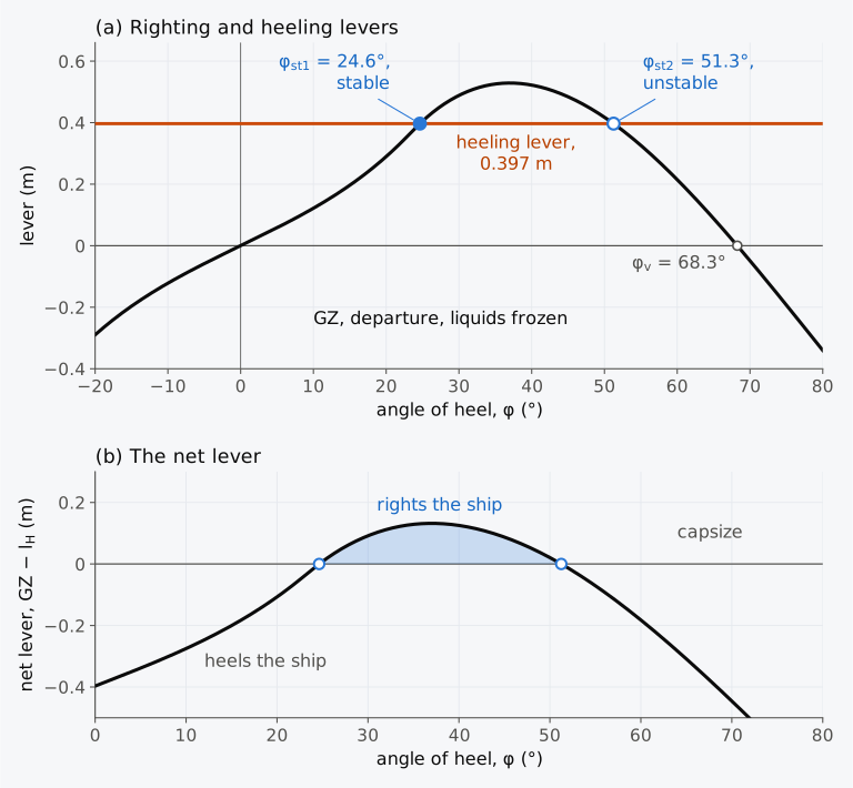
Figure 9.1 A steady heeling moment of 30,000 kN·m on the Series 60 ship in its departure condition, 7707 t with KG = 5.887 m, liquids frozen. (a) The righting and heeling levers, for heel to either side. (b) The net lever.
9.2 Wind and turning
The angles of Sec. 9.1 depend on how the heeling lever changes with the heel, and that depends on the cause of the moment. Many forces heel a ship3. From outside the ship they are beam winds, with or without rolling, the lifting of heavy weights over the side, turns at high speed, grounding, the strain on mooring lines and the pull of a tow-line; from inside, weights shifted across the ship and water trapped on deck. Chapters 4 and 8 treated a weight moved across the ship, whose heeling lever is . Designers and the rules give the levers of the others in simple forms, each resting on assumptions about where the forces act and how they change as the ship heels. In a beam wind and in a steady turn the heeling moment comes from a force on the ship, above the water or at G, and the lateral force of the water on the hull that balances it.
9.2.1 Wind
A beam wind presses on the part of the ship above the water. The ship drifts to leeward until the resistance of the water to its sideways motion balances the wind force, and the two equal and opposite forces form a couple that heels the ship3. The wind force is taken to act at the centroid of the lateral area of the ship above the water, projected on its centreplane, , and the water force at half the draught2,4. If is the wind pressure and the vertical distance between the two forces when the ship is upright, the heeling moment upright is . As the ship heels, both the projected area and the vertical distance between the forces shrink, to a first approximation in proportion to cos φ, so that
Equation (9.3) was proposed by Middendorf and appears in the US Navy criteria2,3. The naval criteria used in this chapter follow the published accounts cited here and illustrate different assessment methods; they are not a statement of the naval requirements currently applicable to a particular ship.
The pressure grows with the square of the wind speed : , where is the density of the air and a coefficient that depends on the shape of the exposed structure. Its average value is 1.2, and values between 0.95 and 1.36 have been measured2. For a wind of equal speed at every height, wind tunnel tests for the US Navy support a pressure of tonnes-force per square metre with in knots2,3. For a nominal wind of 100 kn (51.4 m/s) this is 0.170 t/m², or 1.67 kPa. The wind is slower near the sea surface than higher up, and the US Navy itself uses a coefficient of 0.0195, together with a speed that grows with the height above the water, applied to the lateral area in horizontal strips2,3. Since the lever grows with , a wind 1.4 times as fast nearly doubles it. The pressure and the displacement must be taken in matching units: kilopascals with in kilonewtons, or tonnes-force per square metre with in tonnes, in which case cancels.
The cos² φ law is only an approximation, since the projected area of a heeled ship does not vary as cos φ3, and at 90° a ship still presents an area to the wind. Luquet and co-authors computed the wind loads on a heeled ship with computational fluid dynamics (CFD), which they checked against wind tunnel data only for the ship upright, and with an aerodynamic method. They found the moment to fall with the heel much less than cos² φ gives, with a peak near 15° to 20° of heel5. Taken literally, Eq. (9.3) would allow the Series 60 ship to withstand a steady wind whose lever upright is as large as 1.01 m, almost twice the ship’s largest righting lever, because at 51.3° the lever has fallen to 39 % of its upright value. The IS Code simplifies the other way, with a wind lever that does not change with the heel at all6.
The projected area of the Series 60 hull above its departure waterline, between the contours of its stern and stem, is 424.1 m², with its centroid 1.699 m above the water (Fig. 9.2(a)). A real cargo ship of its size also carries superstructures, masts and hatch coamings; the reference hull has none of these. To give the examples of this chapter a windage of a realistic size, we add one illustrative deckhouse 20.0 m long and 7.5 m high on the deck, of 150.0 m², whose centroid lies 7.137 m above the departure waterline. It is larger than the accommodation drawn over the engine room in Chapters 3 and 10, 14 m long and 5.4 m high, because it stands for that accommodation, the masts, the coamings and the other windage of a real ship together; nothing else is added.
Example 9.2. A beam wind of 100 kn (51.4 m/s). The Series 60 ship in its departure condition, 7707 t at a draught of 6.367 m, has a lateral area above the water of 424.1 m² from the hull, with its centroid 1.699 m above the water, and 150.0 m² from the deckhouse, with its centroid 7.137 m above the water. Using the US Navy’s pressure of 0.170 t/m² (1.67 kPa) for a uniform wind of 100 kn (51.4 m/s) and Eq. (9.3), find the wind heeling lever upright, and the steady angle of heel. The righting lever, with the liquids frozen, is 0.0704 m at 6° and 0.0828 m at 7°.
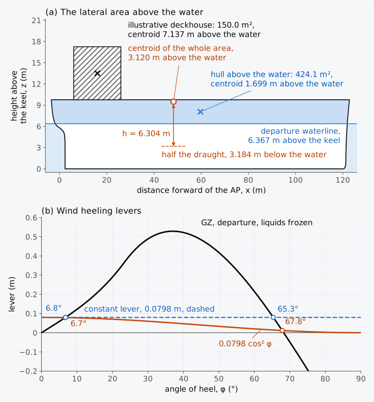
Figure 9.2 The wind on the Series 60 ship in its departure condition. (a) The lateral area above the water, with the illustrative deckhouse; vertical scale three times the horizontal. (b) The heeling lever of a uniform beam wind of 100 kn (51.4 m/s) by Eq. (9.3), and a constant lever equal to its upright value.
9.2.2 Turning
A ship turning at a steady rate is pushed towards the centre of the turn by the water pressure on its hull, and so accelerates towards that centre. In a static treatment this centripetal acceleration is replaced by a centrifugal force , acting outward at G, where is the speed in the turn and its radius, balanced by the lateral force of the water on the hull3. The water force is usually taken at half the draught2,3. Barrass and Derrett take it at the height of the centre of buoyancy7. With half the draught, and with the vertical distance between the forces shrinking as cos φ,
for a ship whose G lies above half its draught2. In a steady turn the ship heels away from the centre of the turn. When the rudder is first put over, the force on the rudder heels the ship briefly the other way, into the turn4,7.
The speed in the turn and its radius are seldom known early in a design. The radius may be taken as half the tactical diameter3, the distance that a ship moves sideways from its original course by the time it has turned through 180°. Wegner combined them into a factor , where is the speed in the turn and the speed on a straight course, and Eq. (9.4) becomes ; for 95 % of 80 cargo ships lay between 0.19 and 0.25, and it lay between 0.30 and 0.35 for a few trawlers2. For passenger ships the IS Code takes the heeling moment in a turn as
in kN·m, with the service speed in m/s, the waterline length and the mean draught in metres and in tonnes, and it limits to 10° the heel that this moment causes6. The Code writes for the draught. Divided by , Eq. (9.5) is Wegner’s lever upright with = 0.200 and for , within his range for cargo ships.
9.3 Dynamic stability
9.3.1 Work and the area under the righting lever
In Sec. 9.1 we found where a ship rests under a heeling moment. How the ship gets there depends on work and energy, as it does for a spring. A weight lowered slowly onto a spring compresses it until the force of the spring equals the weight, and the work done in compressing it is stored in the spring as potential energy. If the weight is then removed suddenly, the spring gives the energy back and oscillates about its original length. A ship heeled slowly stores the work done against its righting moment in this way. A moment that turns a body through a small angle , in radians, does the work . To heel a ship slowly from an angle to an angle , an outside moment must therefore do the work
against the ship’s righting moment, the area under the curve of righting moment between the two angles2,3. The work done in heeling the ship from upright to an angle φ is , where
is the area under the curve of righting levers up to φ, in metre-radians. The work is called the dynamical stability of the ship at that angle4,8. Plotted against the heel, is the curve of dynamical stability4. With Δ in kN and in metre-radians, the work is in kN·m, that is in kilojoules. A ship heeled slowly gains only potential energy, equal to this work4. For the closed hull with unchanged loading and no other heeling moment, the area up to the angle of vanishing stability is the work per unit weight needed to heel the ship from upright to the unstable equilibrium at that angle3. If water floods in or weights shift at a smaller angle, the curve does not hold beyond it. The general criteria of the IS Code set minimum values for the area under the curve, corrected for free surfaces, up to 30° and up to 40°, and for the area between these angles; the downflooding angle replaces 40° if it is less6. As Chapter 4 noted, the name dynamic stability is used although the calculation contains no velocity of roll.
Example 9.3. Dynamical stability to 40°. For the Series 60 ship in its departure condition, 7707 t, Example 8.2 found righting levers of 0.122 m at 10°, 0.291 m at 20°, 0.487 m at 30° and 0.522 m at 40°. Find the area under the curve up to 40° by Simpson’s rule, and the dynamical stability at 40°.
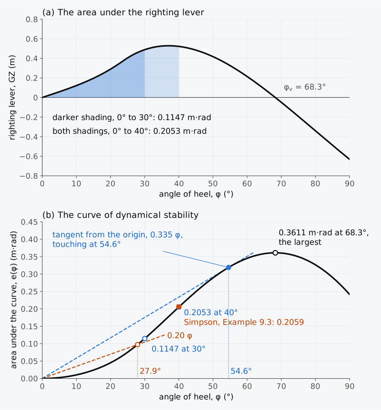
Figure 9.3 Dynamical stability of the Series 60 ship in its departure condition, 7707 t with KG = 5.887 m, liquids frozen. (a) The area under the righting lever. (b) The curve of dynamical stability , with the work of constant heeling levers of 0.20 m and 0.335 m (dashed).
9.3.2 Moseley’s formula
The work can also be found from the heights of G and B. As the ship heels at constant displacement, its weight Δ acts at G and its buoyancy, also Δ, at B, and the vertical distance between G and B grows. The work done on the ship is Δ times that increase3,8. Upright, the vertical distance between G and B is BG. Heeled to φ, it is , measured along the line of action of the buoyancy through the new centre of buoyancy to the foot Z of the perpendicular from G. It grows at the rate GZ. When the ship heels a further small angle dφ, moves parallel to the inclined waterline and keeps its height, while the vertical through it turns through dφ relative to the ship, so that the distance from to the foot of the perpendicular from G grows by GZ dφ8. Thus
and the two routes to the work agree. To find from the hull, let R be the foot of the perpendicular from the upright B to the line of action of the buoyancy; then , with . The distance comes from the movement of the wedges, as in Atwood’s formula, Eq. (8.1): a volume moves from the emerged to the immersed wedge, and, measured normal to the inclined waterline, it moves down by the sum of the distances of the two centroids from that waterline. With the centroids and of the emerged and immersed wedges and the feet and of the perpendiculars from them to the inclined waterline, as in Eq. (8.1), these distances are and . Then
which is Moseley’s formula7,8. Atwood’s formula gives the horizontal movement of B, and Moseley’s its vertical movement relative to the water.
Historical note: Moseley and the area under the curve
For a wall-sided ship, Eq. (4.13) gives the lever up to the angle at which the deck edge goes under or the bilge comes out, . Its integral, with , is
The first term is the work of the lever GM sin φ, and the second the extra work that comes from the transfer of the wedges, which grows with BM.
Example 9.4. A square pontoon (adapted from Attwood8). A pontoon of square section, 6.0 m wide and 6.0 m deep, and 30.0 m long, floats in sea water at a draught of 3.0 m with GM = 0.10 m. Find the area under its curve of righting levers up to 45° (a) by Moseley’s formula and (b) by Eq. (9.9), and the work done in heeling it to 45°.
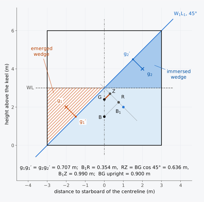
Figure 9.4 The square pontoon of Example 9.4 heeled 45°, drawn in its own frame.
9.3.3 The equation of roll and the energy balance
The work done by a heeling moment and the work done against the righting moment need not be equal. When they differ, the difference goes into the kinetic energy of the rolling ship. Treated as a rigid body rolling about a longitudinal axis, with no damping and no coupling with its other motions, the ship obeys the equation of roll2
where is its radius of gyration in roll, as in Eq. (4.10), and the angular acceleration in rad/s². Multiplying by and integrating from an angle , at which the roll velocity is , to an angle φ gives2
The kinetic energy gained is the work of the heeling moment less the work done against the righting moment. With no heeling moment, at small angles, Eq. (9.10) becomes Eq. (4.10), the free roll of the ship with its natural period .
Equation (9.11) leads to two results2. First, the kinetic energy is greatest where its derivative with respect to φ is zero and its second derivative is negative, that is where and . The stable angle of equilibrium of Eq. (9.2) is where a rolling ship moves fastest. Second, a ship that starts from rest at stops at the angle at which
where the work done against the righting moment has caught up with the work of the heeling moment. If there the righting lever is larger than the heeling lever, the ship rolls back; if the curves cross a second time before any such angle is reached, it capsizes2. With no heeling moment, Eq. (9.12) describes the free roll. A ship released at rest at turns the energy stored in its heel into kinetic energy, moves fastest as it passes upright, and stops at , where the area under its antisymmetric curve from is zero again2.
Equation (9.10) leaves out the resistance of the water to rolling, which takes energy from the ship at every roll. The water that rolls with the hull adds to the inertia of the ship; this water is included when is taken as the effective radius of gyration of Example 4.4. Damping, for example by bilge keels, makes the actual angle somewhat smaller than Eq. (9.12) gives3. The angles found from Eq. (9.12) are therefore upper limits when only damping is added to the same initial state and heeling moment. Waves or a changing wind can supply further energy. Within this prescribed-moment model the angles reached do not depend on the inertia, which sets how fast the ship rolls.
9.3.4 A heeling moment applied suddenly
Suppose a heeling moment is switched on suddenly and then held constant while the ship starts upright and at rest. This is an idealized step load: a real gust develops over time, and a dropped weight also changes the loading and may deliver an impact impulse3. As the ship heels towards the angle of statical equilibrium , the heeling moment does more work than the righting moment absorbs, by the area between the curves in Fig. 9.5(a). The ship reaches with this energy as kinetic energy and heels on, until the area between the curves beyond equals . With , Eq. (9.12) is the condition of equal areas2,4. The angle at which the two areas are equal is called the angle of lurch7. If the righting lever were the straight line , the static angle would be , and Eq. (9.12) would give , and , twice the static angle, as a weight released at rest on top of a spring compresses it twice as far as when it is lowered gently onto it.
Example 9.5. A heeling lever applied suddenly. A heeling lever of 0.20 m, which does not change with the heel, strikes the Series 60 ship upright and at rest in its departure condition, 7707 t with GM = 0.659 m and the liquids frozen. The righting lever is 0.1965 m at 15° and 0.2134 m at 16°, and the area under it, , is 0.0902 m·rad up to 27° and 0.0982 m·rad up to 28°. Find the angle at which the ship would rest if the moment were applied slowly, and the angle to which it heels. Compare both with a straight-line lever .
Figure 9.5(b) shows the roll in time, from Eq. (9.10) solved step by step with the effective radius of gyration, = 6.15 m. Without damping the ship swings between upright and 27.9° every 12.7 s, shorter than its natural period of 15.2 s, because near 15° its righting lever rises more steeply than GM φ. With an illustrative damping, 5 % of the critical value, the swings die away and the ship settles towards 15.2°. The damping is chosen only to show the decay; it is not a property of the Series 60 ship. Animation 9.1 shows the first swings.
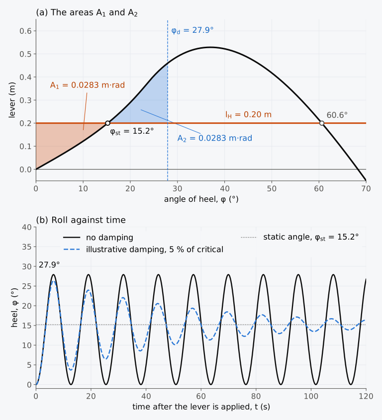
Figure 9.5 A constant heeling lever of 0.20 m applied suddenly to the upright Series 60 ship in its departure condition, liquids frozen. (a) The areas of Eq. (9.12). (b) The roll from Eq. (9.10), with = 6.15 m, without damping and with an illustrative damping.
Animation 9.1 A constant heeling lever of 0.20 m strikes the Series 60 ship, upright and at rest in its departure condition, with the liquids frozen. Above, the midship section heeled to the current angle, starboard to the right, with the water surface level and the time since the moment was applied. Below, the righting and heeling levers against the heel, with a point at the current angle: the area between the curves fills in orange, , while the heeling lever is the larger, and in blue, , beyond 15.2°, and the ship stops at 27.9°, where the two areas are equal, before rolling back. No sound; 15 s.
The angle reached can also be found graphically from the curve of dynamical stability, by plotting the two areas against the heel2,3. The work of a constant lever applied to the upright ship is , a straight line through the origin of Fig. 9.3(b) that rises to at 1 rad, 57.3°, and the ship stops where this line meets the curve again: for 0.20 m, at 27.9°. A larger lever gives a steeper line, which meets the curve farther out, until it only touches it. There the slope of the curve, GZ, equals , so the angle reached is also the second intersection of the levers, and any larger lever capsizes the ship. The tangent from the origin gives the largest constant lever that the upright ship survives when the lever strikes suddenly: for the departure condition 0.335 m, touching the curve at 54.6°, a moment of 25,300 kN·m, 63 % of the largest steady moment of 40,000 kN·m. The moment of Example 9.1, 30,000 kN·m, holds the ship at 24.6° when it is applied gradually, but would capsize the ship if it struck suddenly.
9.3.5 A gust while the ship is rolling
A ship at sea is seldom at rest when a gust strikes it. Suppose the gust arrives when the ship has rolled to windward and is momentarily at rest at an angle . As the ship rolls back towards upright, its righting moment and the heeling moment both act towards leeward, and both add energy3,4. Equation (9.12) now applies from , and the area extends from to (Fig. 9.6(a)). If instead the ship is at the end of a roll to leeward, close to , its righting moment already nearly balances the gust, and it heels little further; beyond it rolls back. The effect resembles pushing a swing, which goes highest when it is pushed as it ends its swing towards the person pushing2.
Predict 9.1. In Example 9.5 the lever of 0.20 m struck the upright ship and heeled it to 27.9°. Suppose the lever strikes the ship when it has rolled 15° to windward and is momentarily at rest. Will the ship heel further than 27.9°, and roughly how much further?
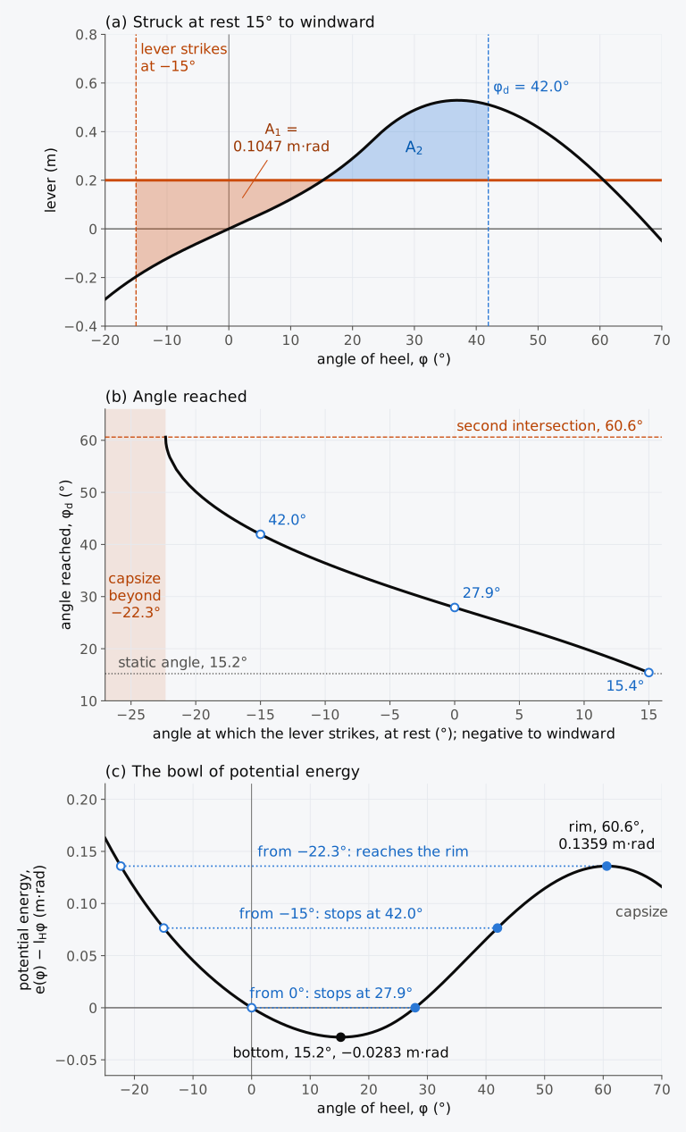
Figure 9.6 A constant lever of 0.20 m strikes the Series 60 ship at rest at an angle of heel, departure condition, liquids frozen. (a) A start 15° to windward. (b) The angle reached. (c) The bowl of potential energy; dotted, three starting levels.
9.3.6 The reserve of dynamic stability
Figure 9.6(b) gives the angle that the ship reaches for every angle, from 22.3° to windward to 15° to leeward, at which the lever strikes it at rest. These results, for a lever that strikes the ship upright or at the end of a roll, have a simple picture, the ball in a bowl of Chapter 1. Under a constant heeling lever , the potential energy of the ship under the heeling moment, per unit of its weight and measured from upright, is , the work done against its righting moment less the work done by the heeling moment2,3. For the lever of 0.20 m of Example 9.5 it falls to −0.0283 m·rad at the static angle, 15.2°, the bottom of the bowl, and rises to 0.1359 m·rad at the second intersection, 60.6°, its rim (Fig. 9.6(c)). Without damping the sum of the potential and kinetic energy stays constant, so a ship released at rest moves until its potential energy returns to its starting value. Released from upright, where the potential energy is zero, the ship stops at 27.9°; from 15° to windward, where it is 0.0765 m·rad, at 42.0°. From more than 22.3° to windward the ship starts above the rim, and capsizes.
With no heeling moment the potential energy per unit weight is itself. For a ship with a negative GM and stable angles of loll, the potential energy falls from upright while the righting lever is negative and rises again beyond the angle of loll, and the upright position is a low ridge between two hollows at the angles of loll on either side.
Predict 9.2. The Series 60 ship in its departure condition, 7707 t, with G raised to 6.696 m above the keel and the liquids frozen, has GM = −0.15 m. It lolls at 18.1°, and its righting lever vanishes at 40.1°. Nudged from the upright, it starts from rest. Will it stop at its angle of loll?
Under a heeling moment, the depth of the bowl below its rim is the further energy that the ship, resting at its angle of equilibrium, can absorb from a gust or a roll before the moment capsizes it: the area between the curves beyond that angle, up to their second intersection, 0.1642 m·rad here. This area is called the reserve of dynamic stability3.
9.3.7 A heeling moment removed or reversed
A heeling moment can vanish as suddenly as it appears. A ship that rests at an angle under a moment that is then removed starts the free roll of Sec. 9.3.3 from , and without damping it rolls to an equal angle on the other side. In this way a ship listed by a load on its crane is thrown over to the other side if the load parts2.
A ship heeled by a steady wind may be brought upright by ballast moved to windward or by anti-heeling tanks. If it then changes course so that the wind comes on the other side, the moment of the ballast and that of the wind act together, and the reversed moment does more harm than a moment removed. In the wind of Example 9.2, with the liquids frozen as there, ballast that brought the Series 60 ship upright would leave it, with the wind on the other side, under a lever of m, which holds it at 12.3° instead of 6.7°. The IS Code therefore advises that a heel caused by the wind should not be compensated by anti-heeling measures unless calculations for the worst cases, such as improper use, failure of the mechanism or an unintended change of course, show that the ship keeps sufficient stability, subject to the approval of the Administration6.
9.3.8 Exploring dynamic stability (Explorer 9.1)
In Explorer 9.1 the Series 60 ship in its departure condition meets a heeling lever of your choice. You can choose how the lever changes with the heel, as a constant, as cos φ or as cos² φ, its value upright, the height of G and the angle at which the lever starts to act, and watch the static angle, the areas of Eq. (9.12) and the angle that the ship reaches. Try a lever that the ship withstands when it is applied slowly but not when it strikes suddenly, and then start it from a roll to windward. With KG above 6.546 m, the height of M, and no lever, the ship lolls, and started near the upright it lurches past its angle of loll.
9.4 Other heeling moments
Passengers crowding to one side, loads lifted over the side, the pull of a tow-line and water trapped on deck heel passenger ships, ships with cranes, tugs and small ships with bulwarks. Several of the criteria that limit these moments use the areas of Sec. 9.3 as well as the angle of equilibrium.
9.4.1 Passengers crowding to one side
Passengers may crowd to one side of a ship to watch something or to escape from a danger, and in an emergency they may also climb to higher decks2. If passengers of average mass move so that their centre of gravity lies a distance from the centreline and a height above where it was, the heeling lever is
in which the second term is the effect of the rise of their weight2. The IS Code limits the heel caused by crowding on a passenger ship to 10°, because at larger heels passengers may panic2. It takes each passenger as at least 75 kg, with the centre of gravity of a standing passenger 1 m above the deck and of a seated passenger 0.3 m above the seat, places the passengers to give the most unfavourable combination of heeling moment and GM, and does not ask for more than four persons per square metre6. The US Navy allows 0.2 m² of deck for each person, five per square metre3, and Wegner recommended allowing for up to seven per square metre, each of 80 kg with some luggage, with the centre of gravity 1.1 m above the deck2.
Example 9.6. The passenger ship criteria. Treat the Series 60 ship, in its departure condition, as a passenger ship. Its free surface moments are 1021.2 t·m. (a) In Exercise 4.14, 400 passengers of 75 kg, standing on the weather deck, raised the displacement mass to 7737 t and KG to 5.906 m, and gave GM = 0.643 m. Let them crowd at four persons per square metre into a band 2.0 m wide along 50 m of the deck on one side, whose outer edge is taken at 8.128 m from the centreline, the half-breadth amidships. Find the heel. (b) Without passengers, 7707 t with KG = 5.887 m, a draught of 6.367 m, a waterline 123.69 m long and GM = 0.659 m, the ship turns at an illustrative service speed of 16 kn (8.23 m/s). Find the heel by Eq. (9.5). Is each heel within the 10° of the IS Code?
9.4.2 A load lifted over the side
Chapter 5 showed that a load hanging from a crane acts at the head of the crane, however high it has been lifted. Lifting a load from the quay therefore adds its mass at the crane head, and G rises and moves off the centreline. On the curve of righting levers the two effects are kept apart3. The righting lever is computed for the ship with the load added at the height of the crane head and with G on the centreline, and the transverse moment of the load becomes a heeling lever,
where is the mass of the load, the distance of the crane head from the centreline and the displacement with the load3. For the lift of Example 5.2, 60 t at 12.0 m from the centreline with the crane head 19.5 m above the keel, = 7767 t, KG = 5.992 m and m. Chapter 5 found a list of 9.4° from the solid GM, with the liquids treated as fixed; on the whole hull the curves cross at 8.9°, because the righting lever of the Series 60 hull rises above GM sin φ at these angles.
For lifting weights over the side, crowding of personnel and turning at high speed, the US Navy asks that the angle of heel be no more than 15°, that the heeling lever there be no more than 0.6 of the largest righting lever, and that the reserve of dynamic stability be at least 0.4 of the total area under the righting lever3. Heels beyond 15° hamper work on board and make it less safe and comfortable for the crew, and the factors 0.6 and 0.4 keep a margin against capsizing that allows for an overload and for errors in heeling levers based on empirical formulae3. The reserve is taken up to the second intersection of the curves, or to the downflooding angle if that is less, and the total area up to the angle of vanishing stability2, on righting levers corrected for free surfaces3.
The IS Code’s recommendations for ships engaged in lifting apply to ships whose keel was laid on or after 1 January 2020, and to ships converted for lifting after that date. They cover lifts of the ship’s own structures and lifts whose heeling moment, as a moment of mass in t·m, exceeds , where GM is corrected for free surfaces and includes the load, is the least freeboard and the moulded breadth. They also apply when the lifted weight raises the ship’s vertical centre of gravity by more than 1 % without a transverse heeling moment6.
The Code gives three routes for lifting. Its main criteria take the load and the lifting appliance into the ship’s displacement and centre of gravity, with no heeling lever6. The ship must then meet the criteria of Part A on its own curve of righting levers, with limits on the heel, set by the design of the lifting appliance, and on the freeboard6. For a lift made within stated limits on the significant wave height, the wind speed, the duration of the lift, the ship’s speed and the traffic, criteria that bring in the wind may replace the main criteria. The corner of the highest continuous deck must stay out of the water; the area under the net righting lever, from the angle of equilibrium to the least of the downflooding angle, the angle of vanishing stability and the second intersection with a wind heeling lever, must be at least 1.4 times the area under that wind heeling lever; and an area of at least 0.03 m·rad must lie under the net righting lever from the angle of equilibrium to the downflooding angle or 20°, whichever is less6.
As an alternative to both, the Code represents the lift by the heeling lever of Eq. (9.14), with the largest static load that the appliance may lift at its outreach and the distance from the centreline of the point at which the load is applied to the appliance6, and asks for a residual area6. Under these alternative criteria, the area between the curves from the angle of equilibrium to 40° or to the angle of the largest residual lever, GZ − , whichever is less, should be at least 0.080 m·rad in exposed waters and 0.053 m·rad in waters that are not exposed, and the angle of equilibrium should be no more than 10°, or less if the deck edge goes under first or the lifting appliance allows less6. Waters count as not exposed where the environment has a negligible effect on the lift, in general sheltered water such as an estuary, a roadstead, a bay or a lagoon over which the wind fetch is no more than 6 nautical miles (11.1 km). Elsewhere the waters count as exposed6.
Example 9.7. The criteria for a lift. In the lift of Example 5.2 the Series 60 ship displaces 7767 t at a draught of 6.408 m, with KG = 5.992 m, the load counted at the crane head and G on the centreline, and the heeling lever is m. The free surface moments of 1021.2 t·m raise G virtually by 0.131 m, and GM with this correction is 0.430 m. The breadth is 16.256 m and the flat deck lies 9.754 m above the keel; the deck edge goes under at 22.8°, and the crane is taken to allow a heel of more than 10°. Computed on the whole hull with the free surfaces, the righting lever is 0.0818 m at 10° and 0.0916 m at 11°, its largest value is 0.384 m, the curves cross a second time at 58.1° and the lever vanishes at 60.1°; the residual lever, GZ − , is largest at 35.2°. The area under the righting lever is 0.00683 m·rad up to 10°, 0.00834 m·rad up to 11°, 0.1178 m·rad up to 35.2°, 0.2223 m·rad up to the second intersection and 0.2231 m·rad up to 60.1°. (a) Check whether the IS Code’s recommendations for ships engaged in lifting apply here. (b) Find the angle of equilibrium and check the three criteria of the US Navy. (c) Check the limits that the IS Code’s alternative criteria set on the angle of equilibrium and on the residual area.
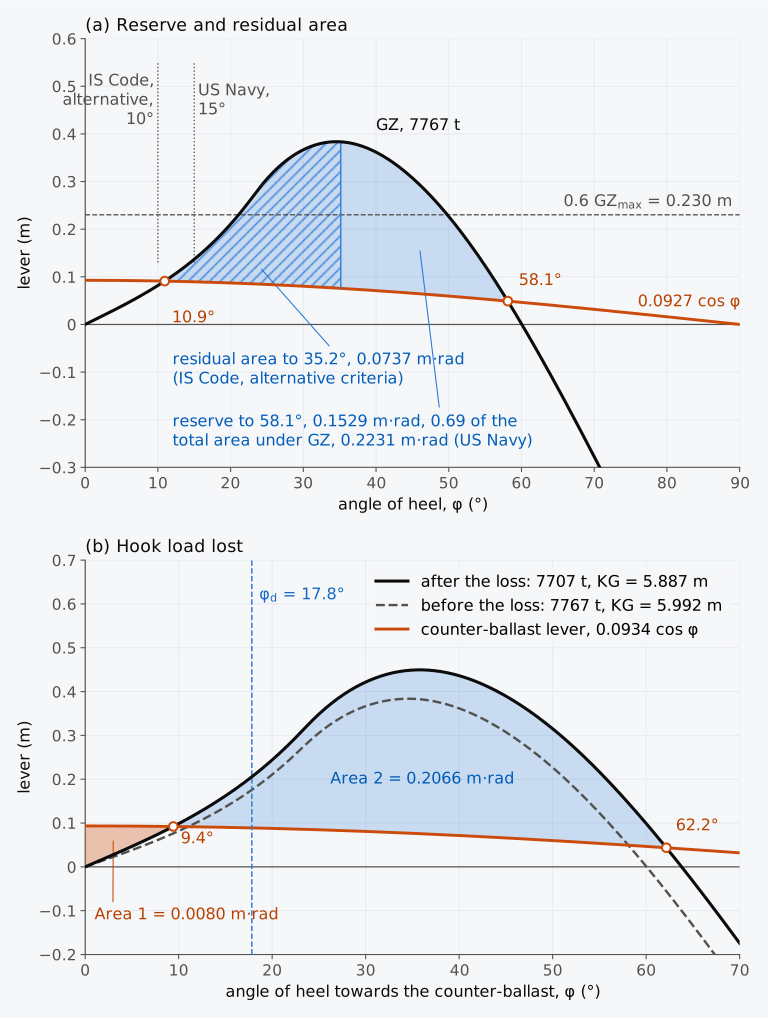
Figure 9.7 The Series 60 ship lifting 60 t over the side (Example 5.2), free surfaces as a virtual rise of G. (a) 7767 t with KG = 5.992 m: the reserve and the residual area, with the limits of the US Navy and of the IS Code’s alternative criteria. (b) The lift balanced by water ballast moved across the ship, and the load then lost.
A ship that lifts heavy loads often keeps itself upright by moving ballast to the side away from the lift. Two equal and opposite moments then act on it, and if the load parts, the moment of the counter-ballast remains and acts suddenly; with a straight-line righting lever the ship would heel to twice the static angle, as Sec. 9.3.4 showed. For the lift of Example 5.2, balanced by water ballast moved across the ship at one level, the ship is left with the displacement and KG of its departure condition and a lever of 720 cos φ/7707 = 0.0934 cos φ m. On the curve corrected for free surfaces this lever would hold the ship at 9.4°, and applied suddenly it heels the ship to 17.8°. Figure 9.7(b) shows the curves before and after the loss. The curve after the loss lies higher, because the load at the head of the crane, 19.5 m above the keel, has gone, and G has fallen from 5.992 m to 5.887 m above the keel.
The counter-ballast lever is its moment times cos φ divided by the displacement without the load, as in the IS Code’s alternative method6. Figure 9.7(b) applies the energy balance to the post-loss condition: Area 1 runs from the starting angle, here upright, to the new equilibrium, and Area 2 from there to the second intersection of the post-loss curves. With no earlier downflooding, Area 2 up to 62.2° is 0.2066 m·rad and Area 1 is 0.0080 m·rad. Their difference is 0.1986 m·rad, and Area 2 is 26 times Area 1.
The Code’s main sudden-loss criterion asks for Area 2 to exceed 1.4 times Area 1 in exposed waters and Area 1 in waters that are not exposed, using the net curves with the actual transverse G6. For this balanced lift, subtracting the counter-ballast lever from the post-loss righting lever gives the same net curve and the same areas, so the ratio of 26 meets that area requirement.
The alternative criterion instead requires Area 2 minus Area 1 to exceed 0.037 m·rad in exposed waters and zero in waters that are not exposed6. There Area 2 ends at the downflooding angle or at the second intersection of the counter-ballast lever with the righting lever of the ship with the load, whichever is less6. That righting lever, dashed in Fig. 9.7(b), meets 0.0934 cos φ again at 58.1°. Area 2 up to 58.1° is then 0.2031 m·rad, and Area 2 minus Area 1 is 0.1951 m·rad, well above 0.037 m·rad.
9.4.3 Towing
A tug can be heeled by a tow-line pulling it sideways through the water (tow-tripping), or by transverse thrust from its own propulsion and steering acting against the tow-line pull (self-tripping)9. The tow-line pulls at the towing hook or bitts, high above the water, while the water resists the sideways motion lower down on the hull, so a large heeling moment can build up quickly. The capsize can be very fast, and tugs are fitted with gear that releases the tow-line at once2. For tugs whose keel was laid on or after 1 January 2020, or which were converted to towing on or after that date, the IS Code represents the largest transverse thrust of the propulsion and steering, balanced by the pull of the tow-line, by the self-tripping lever
where is the bollard pull in kN, a factor for the propulsion, the height of the towing point above the axis of the propellers, and its distance from the centreline, positive towards the side to which the tug heels, as the minus sign implies6. The towing point is the hook, staple or fairlead at which the tow-line pulls6. The Code sets = 0.5 for conventional propellers and rudders. For azimuthing units installed at a single point along the length it sets
where is the longitudinal distance from the towing point to the centreline of the units and the length of the tug as defined by the Load Line Convention. The factor is not less than 0.7 for an azimuth stern drive towing over the stern or a tractor tug towing over the bow, and not less than 0.5 for either towing over its other end; for other arrangements of propulsion and towing it is set case by case6. Because of the second term in the lever, some tugs carry the tow-line on a radial arm or track, which moves the towing point towards the low side4. The Code also gives a tow-tripping lever, from the resistance of the underwater hull drawn sideways at 5 kn (2.57 m/s), and asks that it meet the righting lever before the downflooding angle6.
Under the self-tripping lever the IS Code applies the balance of areas of Sec. 9.3.4: the area between the curves from the angle of equilibrium to the second intersection or the downflooding angle, whichever is less, should be greater than the area between them from upright to the angle of equilibrium6. By Eq. (9.12) with = 0, the tug then turns back before downflooding under the full lever applied suddenly while upright in this idealized model.
An escort tug heels as part of its work. It steers or brakes a ship moving through the water by pulling on a tow-line at an angle, and it is held in equilibrium, at an angle of drift and heeled, by the force of the water on its hull and appendages, its thrust and the pull of the tow-line6. The IS Code takes the heeling lever of an escort tug from full-scale trials, model tests or numerical simulations over the escort speeds, typically 6 to 10 kn (3.1 to 5.1 m/s), and uses its largest value as a constant lever6. Under this lever the Code asks, among other limits, that the area under the righting lever from upright to the least of the second intersection, the downflooding angle and 40° be at least 1.40 times the area under the heeling lever over that range6. This is Eq. (9.12) with = 0 and a margin of 40 %.
9.4.4 Water on deck
Chapter 5 followed the water on the vehicle deck of a ferry. A smaller ship with bulwarks can trap water that it ships over its side in the well that the bulwarks form on its deck. As the ship heels, the water runs to the low side and reduces the righting lever, as the liquid in a slack tank does3. The weight of the water, high in the ship, also raises G. The IS Code advises Administrations to take water trapped on deck into account as far as they think necessary6. It recommends that masters avoid trapping water in deck wells, and reduce speed or change course if the freeing ports, openings in the bulwarks at deck level, cannot drain a well6. The US rules for commercial fishing vessels, 46 CFR part 28, apply to water on deck a residual area like that of the IS Code’s alternative criteria for lifting. Except for vessels operating on protected waters, they ask that the area between the curves beyond the angle of equilibrium, up to 40° or the downflooding angle, be at least a heeling energy found from the water in the well, filled to the top of the bulwark at its lowest point with the ship heeled until that point reaches the water and none of the water draining through the freeing ports. The prescribed calculation keeps the original trim and displacement and allows water to spill over the bulwark; these are assumptions of that assessment, rather than a simulation of the motion of the water on deck10.
9.4.5 Heeling moments acting together
A ship may meet several of these moments at once, and designers allow for their combinations4. Moments that act together add, and so do their levers on the curve of righting levers. The IS Code limits the heels of a passenger ship from crowding and from turning separately6. The German Navy, by contrast, adds to the turning lever the levers of the free surfaces and of a beam wind of 40 kn (20.6 m/s), and allows 15° of heel under their sum2. On the curve corrected for free surfaces, the Series 60 ship heels 3.3° in the turn of Example 9.6. A beam wind of 40 kn from the inside of the turn adds, by Eq. (9.3), of the lever of Example 9.2, m, and the two together heel the ship 4.6°.
9.5 The weather criterion
9.5.1 Wind, roll and gust
A gust that strikes a ship at the end of a roll to windward, the case of Sec. 9.3.5, is the basis of the weather criterion of the IS Code. Each ship to which Part A of the Code applies must show that it can withstand a beam wind combined with rolling6. A steady wind, acting perpendicular to the centreline, heels the ship to the angle , which may not exceed 16° or 80 % of the angle at which its deck edge is immersed, whichever is less. Waves then roll it to windward, from by the angle of roll . At the end of that roll a gust strikes the ship. The area , between the righting lever and the gust lever from their first intersection to the angle , must be at least the area , between the gust lever and the righting lever from to that intersection. The angle is the least of the downflooding angle, 50° and the angle at which the gust lever crosses the righting lever a second time. By Eq. (9.11), the area is the energy per unit weight that the gust and the roll from windward give the ship beyond what its righting moment absorbs up to the first intersection, and is the energy that the ship can still absorb before . The criterion is Eq. (9.12) applied from , and it requires the ship to stop before . IMO’s explanatory notes to the IS Code, issued as MSC.1/Circ.1281, give its purpose: to guard against the capsize of a ship that has lost all propulsive and steering power, and so lies beam on to the wind and the waves11.
Historical note: the origin of the weather criterion
The explanatory notes of MSC.1/Circ.1281 trace the weather criterion to the stability standards of Japan for passenger ships. It first appeared in IMO instruments in 1977, in an attachment to the Final Act of the conference that adopted the Torremolinos Convention for fishing vessels, was extended to passenger and cargo ships by IMO Resolution A.562(14) in 1985, and in 1993 was taken into the IS Code when the Code was first adopted11. In the 2008 Code, adopted by Resolution MSC.267(85), it is one of the mandatory criteria of Part A6.
The two heeling levers do not change with the heel. The steady wind lever and the gust lever are
in metres, where = 504 Pa is the wind pressure, the projected lateral area of the ship and its deck cargo above the waterline in m², the vertical distance in metres from the centre of to the centre of the underwater lateral area, or approximately to half the mean draught, and the displacement in tonnes6. The Code writes , and for , and . At φ = 0 this is Eq. (9.3), the factor 1000 converting the displacement from tonnes to kilograms, since the pressure is in pascals. For ships in restricted service the Administration may reduce the pressure. The explanatory notes model the wind moment with a drag coefficient and a ratio of heights whose product averages 1.22, and take a wind speed of 26 m/s (51 kn), set from casualty statistics by test calculations on 50 ships11. They take the factor of 1.5 between the two levers from gustiness ratios measured over records of about two hours, 1.7 at most and about 1.5 on average; the average was adopted because a capsize could happen within 3 to 8 s, half a period of roll11. Since the lever grows with the square of the wind speed, a lever 1.5 times as large corresponds to gusts 1.22 times as fast as the steady wind.
The criteria of the US Navy for wind and waves also balance areas, with different assumptions. The wind lever falls as cos² φ, Eq. (9.3), with a nominal wind speed that depends on the ship’s service; the ship rolls 25° to windward from the steady angle; and the area between the curves on the leeward side must be at least 1.4 times the area on the windward side, with the heeling lever at the steady angle no more than 0.6 of the largest righting lever3. The factor 0.6 leaves room for gusts and for the rough estimate of the heeling lever3. The roll of 25° is an assumed amplitude, judged plausible in heavy weather, and the extra 40 % of area covers gusts and errors in the calculation, while the energy that damping takes out is left out of the balance3. A ratio of 1.4 goes with a cos² lever in the criteria of the US Navy, and a ratio of 1.0 with a constant lever in IMO’s12.
9.5.2 The angle of roll
The IS Code gives the angle of roll to windward, in degrees, as
where OG = KG − T is the height of G above the waterline, positive upward, and the mean moulded draught, written in the Code6. The factor depends on the ratio of breadth to draught, and on the block coefficient . The factor is 1.0 for a round-bilged ship with no bilge keels or bar keel and 0.7 for a ship with sharp bilges; for a ship with bilge keels, a bar keel or both, it depends on their total area . The factor depends on the natural period of roll, which may be estimated, in the absence of better information, by Eq. (4.11), with GM corrected for free surfaces. Table 9.1 gives the four factors, with linear interpolation between the values listed. Anti-rolling devices are left out unless the Administration is satisfied that they remain effective when their power fails suddenly6.
Table 9.1 The factors of the angle of roll in Eq. (9.16), from the 2008 IS Code6. Intermediate values are found by linear interpolation, and the end values marked ≤ and ≥ apply beyond the range listed.
(a) The factor
| ≤ 2.4 | 1.00 |
|---|---|
| 2.5 | 0.98 |
| 2.6 | 0.96 |
| 2.7 | 0.95 |
| 2.8 | 0.93 |
| 2.9 | 0.91 |
| 3.0 | 0.90 |
| 3.1 | 0.88 |
| 3.2 | 0.86 |
| 3.4 | 0.82 |
| ≥ 3.5 | 0.80 |
(b) The factor
| ≤ 0.45 | 0.75 |
|---|---|
| 0.50 | 0.82 |
| 0.55 | 0.89 |
| 0.60 | 0.95 |
| 0.65 | 0.97 |
| ≥ 0.70 | 1.00 |
(c) The factor
| 0 | 1.00 |
|---|---|
| 1.0 | 0.98 |
| 1.5 | 0.95 |
| 2.0 | 0.88 |
| 2.5 | 0.79 |
| 3.0 | 0.74 |
| 3.5 | 0.72 |
| ≥ 4.0 | 0.70 |
(d) The factor
| (s) | |
|---|---|
| ≤ 6 | 0.100 |
| 7 | 0.098 |
| 8 | 0.093 |
| 12 | 0.065 |
| 14 | 0.053 |
| 16 | 0.044 |
| 18 | 0.038 |
| ≥ 20 | 0.035 |
The explanatory notes to the IS Code describe Eq. (9.16) as a combination of two formulae. A formula from the USSR supplied the factors , and , and a Japanese formula, built on the resonant roll of a ship in regular beam waves, was reduced by a factor of 0.7 for irregular waves; the constant 109 was set from test calculations made by members of a working group of IMO, among them Japan’s on 58 of its ships11. The tables rest on data from ships with below 3.5, with between −0.3 and 0.5, and with a roll period below 20 s. Beyond these limits the tables still give their end values, and the IS Code allows the angle of roll to be found by model tests as an alternative; the Administration may also accept such tests for any ship6. Here a ship outside these limits is given the arithmetic of the criterion and its ratio of areas, but no verdict. That is a cautious choice made in these chapters, not a rule of the Code.
9.5.3 The weather criterion of the Series 60 ship
The criteria of the IS Code apply to the righting lever with the free surfaces accounted for6. The free surfaces are taken here as a virtual rise of G at every angle, as in Sec. 8.4.3. For the departure condition, with free surface moments of 1021.2 t·m, the rise is 0.133 m. With KG = 5.887 + 0.133 = 6.020 m the corrected lever has = 0.450 m at 35.8° and vanishes at 63.8°, as Chapter 8 found with the unrounded rise. The IS Code asks for the GM of the roll period to be corrected for free surface effect, but defines OG as KG − T, with no such correction6. OG therefore takes the KG of the loading condition, 5.887 m, without the virtual rise. The manual of the stability program PIAS states that it applies OG in this way13.
Example 9.8. The weather criterion. The Series 60 ship in its departure condition displaces 7707 t at a mean draught of 6.367 m, with = 16.256 m, = 123.69 m, = 0.596, KG = 5.887 m, GM = 0.659 m and free surface moments of 1021.2 t·m. The deck edge is immersed at 23.1°. The windage is that of Example 9.2, 574.1 m² with its centroid 3.120 m above the water. The ship has illustrative bilge keels 36.0 m long and 0.40 m deep on each side, and no openings that flood below 50°. Its righting lever, corrected for free surfaces, and the area under it are:
φ (°) 2 3 4 13 14 50 GZ (m) 0.0184 0.0277 0.0371 0.1348 0.1481 0.3152 (m·rad) 0.00032 0.00072 0.00129 0.01439 0.01686 0.24127 The corrected lever falls below the gust lever again at 62.4°. Apply the weather criterion.
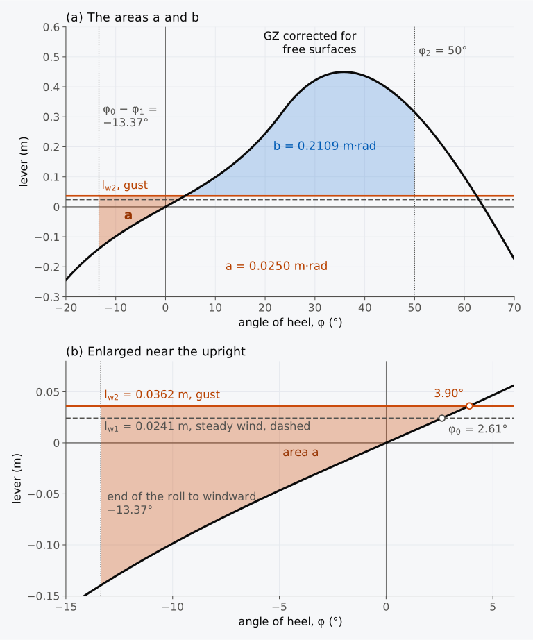
Figure 9.8 The weather criterion for the Series 60 ship in its departure condition (Example 9.8), free surfaces as a virtual rise of G. (a) The areas and . (b) Enlarged near the upright.
On arrival, 1385.0 t·m of free surface moments in 7236 t raise G by 0.191 m, to KG = 6.320 m. The ship then trims 0.77 m by the head, and its curve of righting levers, computed in Chapter 8 on the whole hull at that trim, has a slope at the origin of 0.336 m. Corrected for free surfaces, GM = 0.336 − 0.191 = 0.145 m. The KM of the ship on even keel, 6.497 m, would give 0.177 m, but the trim matters here, and the IS Code asks that the stability then be calculated for the actual trim6. The GM of the roll period is therefore the GM that belongs to the curve from which the areas are taken, 0.145 m, and with it the arrival condition does not meet the Code’s minimum of 0.15 m for GM6. Example 5.4 found that, with the same tanks, the condition meets this minimum on the even-keel KM; at its actual trim it does not. The steady wind heels the ship to 8.7°, and the roll period of Eq. (4.11) is 32.6 s. The tables of the angle of roll rest on data from ships whose roll period is below 20 s, and for a ship outside that range the Code allows the angle of roll to be found by model tests6. Its table of gives the end value 0.035 for periods of 20 s or more6. With that value = 14.9° and = 11.2, larger than at departure, because a ship with so small a GM stores little energy in its roll to windward. The ratio is reported here without a verdict. In this comparison, taken by itself, the weather criterion favours the smaller GM. The Code’s general criteria on GM and on the curve of righting levers apply as well, and this condition fails one of them6.
9.5.4 Weather criterion calculator (Calculator 9.1)
Calculator 9.1 applies the weather criterion to the Series 60 ship in its departure or arrival condition, step by step as in Example 9.8. You can change KG, the free surface moments, the windage and its height, the bilge keels and the downflooding angle, and use the table of extended to roll periods of 30 s in MSC.1/Circ.1627, IMO’s interim guidelines on the second generation intact stability criteria14. It uses the levers of the whole hull every degree, corrected for free surfaces as a virtual rise of G, with KM at the trim of each condition. It flags a GM below 0.15 m and a ship outside the limits of the data on which Table 9.1 rests. For such a ship, and whenever the extended table is selected, it shows the arithmetic and the ratio of areas without a verdict on the weather criterion.
9.5.5 The righting lever in waves
Both areas of the weather criterion are taken from the curve of righting levers, computed with the sea surface a plane. At sea the surface along the ship is a wave profile, and waves change the ship’s stability most in head and following seas, when they are about as long as the ship2. With a crest amidships, the full midship sections are immersed deeper, while the water falls at the fine ends and the waterline narrows there. With a trough amidships, the ends are immersed deeper and the waterline widens. The breadths enter the transverse second moment of the waterplane to the third power, so BM, and with it GM, falls on the crest and rises in the trough2. How much depends on the form, and for some forms and draughts the change reverses2; the flared bows and wide transom sterns of container ships enlarge it2.
Figure 9.9 shows the effect on the Series 60 ship in its departure condition, with the liquids frozen. The wave is sinusoidal, 121.92 m long, as long as the ship, and 4.07 m high from trough to crest, a steepness of 0.0334, which MSC.1/Circ.1627 uses in its simplest check of the loss of stability on a wave crest14. The calculation is quasi-static: the ship is held at rest on the wave, first with the crest and then with the trough amidships, and is balanced in sinkage and trim, as the guidelines ask in their more detailed check14. The pressure below the wave profile is taken as hydrostatic, which neglects the Smith effect, the difference between the actual pressure under a wave and the static pressure at the depth below its surface15. With this pressure, the upward force on the hull equals the weight of water of its volume below the wave profile and acts through the centre of that volume, B, and the righting lever follows from B as in still water. On the sloping surface the pressure also pushes the hull along the wave. That longitudinal force, and its moment in pitch, are left out of the balance, in which the ship sinks and trims until it displaces its weight with B in the transverse plane through G. Taken into account, they would change the trim upright by 0.02 m on the crest and 0.01 m in the trough, and its GM and righting levers by less than 0.001 m. The motions of the ship are left out.
With the crest amidships, the water stands 1.35 m above the still waterline at the midship section, and the deck edge there goes under at 14.0° instead of 23.1°. Read from the slope of each curve at the origin, the GM is 0.660 m in still water, where KM − KG gives 0.659 m, and 0.601 m on the crest, only 9 % less. The BM falls by 0.18 m, but B rises by 0.12 m, because the volume gained amidships lies higher than the volume lost at the ends. The largest righting lever, however, falls from 0.529 m to 0.303 m, by 43 %, far more than the GM suggests, and the range of stability shrinks from 68.3° to 61.7°. In the trough the GM rises to 1.036 m and the largest lever to 0.694 m.
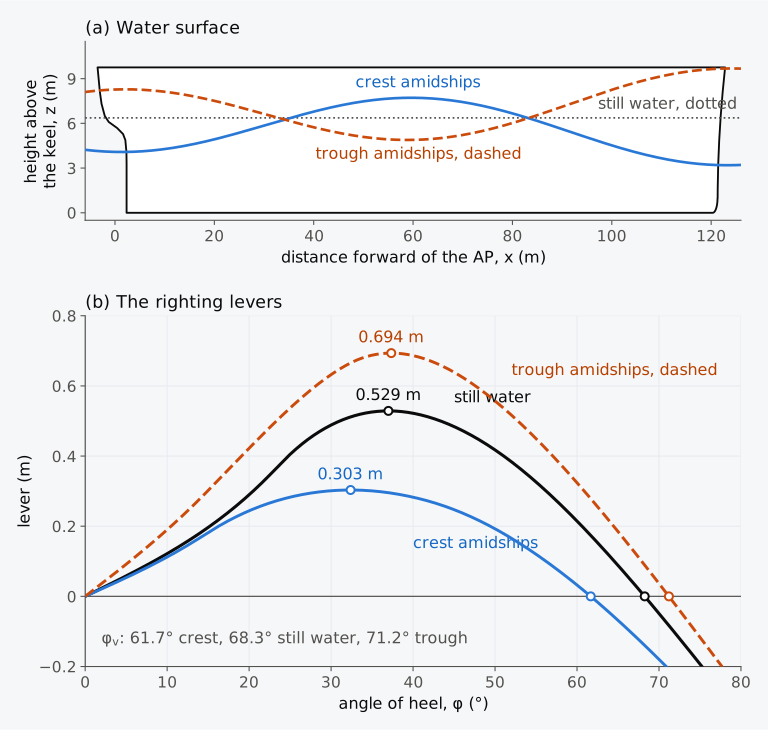
Figure 9.9 The Series 60 ship in its departure condition, liquids frozen, held at rest on a sinusoidal wave 121.92 m long and 4.07 m high. (a) The water surface along the upright ship with the crest and with the trough amidships; vertical scale three times the horizontal. (b) The righting levers.
If a ship stays on a crest for long enough, this loss can capsize it, a failure called pure loss of stability2. On the crest of Fig. 9.9 the Series 60 ship keeps a positive lever up to 61.7°, but the loss grows roughly in proportion to the wave height3. The danger is greatest in following seas, in which the ship moves with the waves and stays longer on each crest2,3.
A ship that meets crests and troughs in turn has a righting moment that varies periodically. At small angles, with the mean metacentric height and the amplitude of its variation, Eq. (9.10) with no heeling moment becomes
a Mathieu equation, in which is the circular frequency at which the ship meets the waves2. In this linear model without damping its solutions can grow without limit, and the large roll that results is called parametric roll2. The most dangerous case is , where is the natural circular frequency of roll with the mean GM; the ship then meets the waves at half its natural period of roll2,3. In low waves differs little from the GM in still water, and from . Parametric roll can develop rapidly, sometimes before the crew recognizes its onset2; Chapter 4 described it on the Maersk Essen. A container ship 262 m long rolled 35° to 40° in a storm in the North Pacific and lost a third of its nearly 1300 containers2.
The period at which a ship meets the waves, the period of encounter, is
where λ is the wave length, the speed of the waves in deep water, the ship’s speed and μ the angle between its course and the direction in which the waves travel, 0° in following seas, 90° in beam seas and 180° in head seas2, whichever side the waves come from. It is measured from the direction of the waves, not from north. The absolute value keeps the period positive for a ship that overtakes the waves. In the formula for the frequency of encounter in the ITTC Dictionary of Hydromechanics, μ = 0° means head seas instead15.
Example 9.9. When parametric roll can start. The Series 60 ship meets regular waves 121.92 m long in deep water. Its breadth is 16.256 m, and with GM corrected for free surfaces, 0.526 m on departure and 0.145 m on arrival, Eq. (4.11) with = 0.3785 and 0.3821 gives its natural periods of roll in still water as 16.97 s and 32.6 s. Find the speed and the period of the waves. Restrict the ship’s speed to less than the wave speed. For each condition, find whether it must meet the waves in head seas or in following seas, and at what speed, to meet them at half its natural period of roll (a) in low waves, in which its mean GM is that of still water, and (b) in waves 4.07 m high, in which its mean GM, found with the liquids frozen, is 0.105 m higher than in still water on departure and 0.119 m higher on arrival.
Neither failure enters the weather criterion, since its roll and its gust act on the still-water curve, although the IS Code warns that a large variation of the righting lever between trough and crest can cause both6. MSC.1/Circ.1627 assesses pure loss of stability and parametric roll as failure modes of their own14. In IMO’s usage, dynamic stability means the resistance of a ship to stability failures in a seaway15, a wider sense than the dynamical stability of Sec. 9.3.1, the work done in heeling a ship slowly.
9.6 The Concordia
With the heeling levers and the energy balance of this chapter, we can return to the Concordia. The Transportation Safety Board of Canada evaluated the stability of the Concordia in its condition at the time, 442 t with a GM corrected for free surfaces of 0.72 m, using a computer model of its hull and tanks1. The yacht’s curves are given in the Board’s report, and none of its data is used in the calculations of this chapter.
The steady heel of the Concordia was an angle of statical equilibrium, where the heeling lever of the wind on its sails and rigging met its righting lever. Research at the Wolfson Unit for Marine Technology and Industrial Aerodynamics, at the University of Southampton, found that the wind lever of a sailing vessel falls with the heel roughly as , more slowly than the cos² φ of Eq. (9.3), and it grows with the square of the wind speed2. The Board calculated that apparent winds of 20 to 28 kn (10.3 to 14.4 m/s) would hold the yacht at about 23°, near what was observed1. With more wind the steady heel rose steadily to about 38°. Beyond that the two curves ran so close together that apparent winds of about 27 to 37 kn (13.9 to 19.0 m/s) could give any steady heel from about 38° to 68°, and a heel of almost 70° needed only a little more wind1. At 56.5° the galley door went under, and at 58.4° the mess door1. The yacht’s stability booklet counted on the buoyancy of its deckhouses, which gave its curve a second rise beyond about 60°; with the lee doors open, the Board left out the buoyancy of the forward deckhouse beyond about 58°, and beyond about 88° that of the after deckhouse1.
The wind from a squall may also blow downward. The Board found that from a steady heel of about 28°, a wind inclined 30° below the horizontal, at 23 to 31 kn (11.8 to 15.9 m/s), would have overcome the yacht’s righting lever1. It concluded that the wind at the knockdown most likely lay between 25 and 50 kn (12.9 and 25.7 m/s), with probably a vertical component, and found no evidence that a microburst, a small and intense downdraught, had occurred1.
The stability booklet gave the master curves of the largest steady heel that would keep the yacht clear of downflooding in gusts and in squalls1. The stability codes of the United Kingdom for sailing vessels define such curves2. The wind lever that would just heel the vessel to its downflooding angle has the value when the vessel is upright, where is the righting lever at . This lever is halved, because a gust 1.4 times as fast as the mean wind doubles the lever. The angle at which the halved lever meets the righting lever is the largest steady heel at which a gust of that size would not bring the openings under water. For the Concordia the gust curve gave a steady heel of 24°, on the basis that gusts seldom exceed 1.4 times the hourly mean wind; squalls can be much stronger1. Under a squall, the yacht sailed for two or three minutes at 23°, just inside the 24° limit of the gust curve. In the Board’s reading of the squall curves, the largest safe wind speed fell from 50 to 55 kn (25.7 to 28.3 m/s) before the master left the deck, against an apparent wind of 15 to 18 kn (7.7 to 9.3 m/s), to 35 kn (18.0 m/s) two or three minutes before the knockdown, against 23 kn (11.8 m/s). The ratio of the two, the margin of safety, fell from 3.2 to 1.5 in that time1.
The dynamic picture of Sec. 9.3.4 applies only in part to a sailing vessel. Gusts build up over 10 to 20 s, longer than the natural roll period of most sailing vessels, and the sails damp the roll strongly, so the vessel heels towards the steady balance of levers rather than past it2. Read with Sec. 9.3, the Board’s calculations do not need an overshoot to explain the knockdown. The yacht’s steady heel of 23° rested on a stretch of its curve where a modest rise in the wind moved the equilibrium a long way, and a steady wind somewhat stronger than the wind it was carrying sail for had no equilibrium short of its open doors.
9.7 Heeling moments and dynamic stability in industry today
This section describes practice in 2026.
The weather criterion and its alternatives. The weather criterion of Sec. 9.5 is mandatory under Part A of the IS Code6. Where the tables of Eq. (9.16) do not apply, or where the Administration accepts it, the Code allows the levers and the angle of roll to be found by model tests6. IMO’s interim guidelines for these tests, MSC.1/Circ.1200, measure the wind heeling moment in a wind tunnel, at a full-scale wind speed of 26 m/s with a uniform profile, together with the drift force of the water in a towing tank, and they allow the steady wind lever to depend on the heel. They take the angle of roll as the resonant amplitude measured in regular beam waves, multiplied by 0.7 for the irregularity of a real sea16.
The dead ship condition of the second generation criteria. The interim guidelines on the second generation intact stability criteria, MSC.1/Circ.1627, assess the dead ship condition, a ship without propulsion or steering in beam wind and waves, at two levels14, as they assess the pure loss of stability and the parametric roll of Sec. 9.5.5. The first level is the weather criterion14, with a modified table of the factor . The table runs to roll periods of 30 s, where falls to 0.020, and above 18 s its values are lower than those of Table 9.1, 0.032 instead of 0.035 at 20 s. For the Series 60 ship on arrival, with its roll period of 32.6 s, beyond the end of the extended table too, its end value, = 0.020, gives an angle of roll of 11.3° instead of 14.9°. The second level computes, from the roll of the ship in irregular beam waves with a gusty wind, the probability of stability failure in an hour of exposure in each of a set of sea states, failure being a roll beyond a failure angle. These probabilities are weighted by the frequency of the sea states, and the result must not exceed 0.06 for the ship to pass14. Bulian and Francescutto proposed a way of applying the first level with operational limitations, in which a modified reference wind speed, with a set probability of being exceeded, replaces the standard speed17. Marlantes, Kim and Hurt compared two independent implementations of the guidelines, applied them to a barge and two container ships that passed both levels for the dead ship condition, and recommended that users be able to vary the wind pressure and the wave steepness18.
Methods in software. Bentley’s page for its MAXSURF software states that the program evaluates stability criteria from the curve of righting levers and the results of equilibrium, with heeling arms and moments that can be customized for specific regulations19. NAPA’s release of 2020 added a criterion for the calculation of Sec. 9.3.4, the largest dynamic angle reached under a heeling moment applied in one step20. The sources consulted for this section describe no format for exchanging heeling levers between programs.
The shape of the wind lever. The constant lever of the IS Code and the cos² φ law of naval rules are both simplifications. A wind tunnel test under MSC.1/Circ.1200 may give a lever that changes with the heel in its own way16, and the moment computed by Luquet and co-authors first rises with the heel5. Hayes and co-authors reassessed the wind speeds used for intact stability and recommended a gust factor of about 1.4 on the wind speed, applied most easily by doubling the nominal heeling moment12.
9.8 From heeling moments to the inclining experiment
The righting levers, and with them every angle and area of this chapter, depend on the height of G. A rise of G takes δKG sin φ from the righting lever at every angle, and with it some of the area under the curve, while a heeling lever proportional to KG − T/2, like that of a turn, grows. The KG of a loaded ship comes from the weight table of Chapter 3, which starts from the mass and centre of gravity of the empty ship, the lightship. Within its scope, SOLAS requires every passenger ship, and every cargo ship 24 m long or more, to be inclined on completion to determine the elements of its stability21, and Part B of the IS Code repeats this6. In Chapter 10 we will see how the inclining experiment finds the lightship’s centre of gravity, by moving known weights across the deck and measuring the heel that results.
Summary
- A heeling moment divided by the displacement is the heeling lever, Eq. (9.1). The ship rests where the heeling lever meets the righting lever, and the equilibrium is stable where the righting lever rises more steeply, Eq. (9.2). A steady heeling moment shortens the range of stability to the second intersection of the curves.
- The wind lever upright is , with the pressure proportional to the square of the wind speed. The cos² φ law of Eq. (9.3) is an approximation; the IS Code takes the lever as constant.
- In a turn the centrifugal force at G and the water force at half the draught give a lever proportional to and KG − T/2, Eq. (9.4); the IS Code’s moment for passenger ships, Eq. (9.5), corresponds to Wegner’s factor = 0.200.
- The work done in heeling a ship slowly to an angle is its weight times the area under the righting lever, its dynamical stability, Eqs. (9.6) and (9.7). Moseley’s formula, Eq. (9.8), gives it from the rise of G above B, and for a wall-sided ship it has the closed form of Eq. (9.9).
- The equation of roll without damping, Eq. (9.10), turns into the energy balance of Eq. (9.11). A ship that starts from rest stops where the areas between the curves balance, Eq. (9.12); with damping, this angle is an upper limit. A constant moment applied suddenly to the upright ship at rest heels it well past the static angle, to the angle of lurch, twice as far for a straight-line lever and 1.8 times as far for the Series 60 ship. A moment that the ship withstands when it is applied slowly can capsize the ship when it strikes suddenly. The tangent from the origin to the curve of dynamical stability gives the largest constant lever that the upright ship survives when it strikes suddenly.
- A gust that strikes a ship at the end of a roll to windward does the most harm, because the ship’s own righting moment adds the energy of the roll.
- The reserve of dynamic stability, the area between the curves beyond the angle of equilibrium up to their second intersection, is the energy that the heeled ship can still absorb. A lolled ship nudged from the upright lurches past its angle of loll, and a bulk cargo that shifts in a roll can take much of the reserve, as Exercise 9.15 shows.
- A moment that is removed suddenly from a ship at rest at its angle of heel throws it to an equal angle on the other side. This holds without damping and on an unchanged, antisymmetric lever curve. Ballast that corrects a wind heel adds its moment to the wind’s when the wind comes on the other side.
- Crowding passengers give the lever of Eq. (9.13), a lift over the side Eq. (9.14) with the load at the crane head, and the thrust of a tug against its tow-line the self-tripping lever of the IS Code. The levers of moments that act together add.
- For a lift the US Navy limits the heel to 15° and compares the reserve with the whole area, while the alternative criteria of the IS Code limit the heel to 10° and ask for a residual area; the lift of the Series 60 ship meets the first and fails the second. The Code’s main criteria take the load into the ship’s centre of gravity instead, and its criteria for lifts within stated limits of weather add a wind heeling lever. Counter-ballast that is left when the hook load parts acts as a sudden moment.
- The IS Code’s criterion for tugs balances the areas so that, in the idealized model, a tug struck by its self-tripping lever while upright turns back before downflooding. For an escort tug it asks for a margin of 40 % on the area under its largest escort lever.
- The weather criterion of the 2008 IS Code, Part A, combines a steady wind, a roll to windward and a gust, Eqs. (9.15) and (9.16), and requires the area to be at least the area . Its tables rest on data from ships with below 3.5, between −0.3 and 0.5 and roll periods below 20 s.
- Both areas of the weather criterion come from the still-water curve. In a quasi-static calculation on a wave as long as the ship and 4.07 m high, the Series 60 ship loses 9 % of its GM but 43 % of its largest righting lever with the crest amidships, and gains in the trough. If the ship stays on a crest long enough, the loss can capsize it, and a ship that meets the waves at half its natural period of roll, Eq. (9.17), can build up parametric roll. In higher waves that period follows the mean GM in the waves; for the Series 60 ship in waves 4.07 m high, the mean GM is about 0.1 m above the GM in still water.
- The wind lever of a sailing vessel falls roughly as . The Concordia sailed at a steady heel on a stretch of its curve where a modest rise in the wind moved the equilibrium a long way, past the angles at which its open doors went under.
Notes on the data
The Concordia. The yacht’s voyage, the knockdown, its sail area and its condition at the time are from the report of the Transportation Safety Board of Canada1. The yacht’s curves of righting levers and wind heeling levers are in the report and are not reproduced, and none of its data is used in the calculations of this chapter.
The levers of the Series 60 ship. The righting levers of the departure and arrival conditions are those of Chapter 8, computed on the whole hull at constant displacement with the trim free, every degree from 0° to 90°, with the liquids frozen. Negative angles follow from the symmetry of the hull, with G on the centreline. Between the computed angles the levers are interpolated by a cubic spline, and areas under the curves are integrals of that spline. Sections 9.1 to 9.4 use the levers with the liquids frozen, as Chapter 8 does, except where a criterion is checked. There, as in the weather criterion of Sec. 9.5, the free surfaces are a virtual rise of G at every angle, 1021.2/7707 = 0.133 m on departure and 1385.0/7236 = 0.191 m on arrival. The corrected lever is KN − KG sin φ, with KN of the whole hull every degree and KG = 6.020 m on departure and 6.320 m on arrival, the printed KG plus the printed rise, so that the examples, the exercises and Calculator 9.1 agree to the last digit; it differs from the lever with the unrounded KG by less than 1 mm. The comment of Example 9.6 and Sec. 9.4.5 use this lever of the departure condition. So do the counter-ballast of Sec. 9.4.2 and Exercise 9.15. The reversed wind of Sec. 9.3.7 keeps the liquids frozen. In Sec. 9.5 KG is raised by the rise for the GM of the roll period, while the factor of Eq. (9.16) takes the KG without it. Example 9.6 subtracts the rise from GM, with 1021.2/7737 for the ship with its passengers. For the lift of Example 9.7 the levers are computed on the hull at 7767 t with KG = 5.992 m, with that of the departure condition, since Example 5.2 does not give the position of the crane along the ship. The example adds the free surfaces as a virtual rise of 1021.2/7767 = 0.131 m. The counter-ballast of Sec. 9.4.2 is illustrative: water moved across the ship at one level, so that after the load is lost the ship has the displacement, KG and free surface moments of its departure condition, with no openings that flood before the second intersection.
The windage. The lateral area of the hull above the water is the integral, over the height from the waterline, at the even-keel draught of the condition as printed, to the flat deck 9.754 m above the keel, of the length of the hull between its stern and stem contours, which Chapter 1 takes from Todd’s report. At the deck the hull runs from 3.51 m aft of the AP to 122.80 m forward of it. The draught is 6.367 m on departure; the arrival condition, trimmed 0.77 m by the head, is taken at its even-keel draught of 6.034 m. The deckhouse, 20.0 m long and 7.5 m high, and the bilge keels, 36.0 m long and 0.40 m deep on each side, are illustrative and are not part of the reference hull. Masts, cranes and hatch coamings are left out. The downflooding angle is taken to lie beyond 50°.
The lolled ship and the bulk cargo. The levers of Predict 9.2 are those of Chapter 8 for the departure displacement with KG = 6.696 m, on the whole hull with the trim free and the liquids frozen. The shift of Exercise 9.15 is illustrative: its moments are those of Eq. (5.11), rounded to the tonne-metre, for a hold 20.0 m long with vertical sides 14.0 m apart and a cargo of 1.6 t/m³ with an angle of repose of 30°, whose level surface a roll to 42° leaves tilted 12° in the ship, clear of the hatch and of the bottom.
The levers in waves. The levers of Fig. 9.9 are computed on the whole hull by the method of Chapter 8, every degree from 0° to 90°, at the displacement and KG of the departure condition with the liquids frozen, with the water surface replaced by a sinusoidal wave 121.92 m long and 4.07 m high that travels along the ship. At each heel the ship sinks and trims until it displaces its weight with B in the transverse plane through G; the longitudinal force of the pressure on the sloping surface is left out of this balance. Upright, it trims 0.89 m by the stern with the crest amidships and 1.40 m by the head with the trough amidships. The height of the wave at each point of the hull is taken at the horizontal distance of the point along the wave, the pressure below the wave profile is hydrostatic, and the ship is held at rest. In still water the method reproduces the levers of Chapter 8. The GM in waves is the slope of the curve at the origin, found from the lever at 0.25°, and BM is GM + KG − KB of the upright ship. For the mean GM of Example 9.9 the crest is placed amidships and at every 0.1λ up to 0.5λ forward and 0.4λ aft of it14, in both conditions with the liquids frozen. The change of the mean is measured from the GM in still water found in this way, 0.660 m on departure and 0.336 m on arrival, less on arrival than KM − KG because it trims 0.77 m by the head, and added to the GM corrected for free surfaces of Example 9.8 and Exercise 9.10. Section 9.5.3 takes the arrival GM from this 0.336 m.
The roll in time. The roll of Fig. 9.5(b) and Animation 9.1 is computed from the equation of roll by an adaptive Runge–Kutta method, with = 6.15 m, the effective radius of gyration , which includes the water moving with the hull. The damped curve adds a linear damping moment of 5 % of the critical value, chosen only to show the decay.
The turn. The service speed of 16 kn (8.23 m/s) in Example 9.6 and the beam wind of 40 kn (20.6 m/s) that Sec. 9.4.5 adds to the turn are illustrative.
The tug. The tug of Exercise 9.13 is illustrative, with its bollard pull, towing point and righting levers; the levers given every degree are read from a cubic spline through levers chosen every 5°, and the areas are integrals of that spline.
Explorer 9.1 and Calculator 9.1. Both use KN of the whole hull every degree from Chapter 8, for the departure and arrival displacements, with GZ = KN − KG sin φ for the KG chosen. KN was computed with the trim free at the KG of each condition, and Chapter 8 found it to differ from KN with KG = 0 by less than a millimetre. The KM from which both take GM is KG + GM with GM the slope of the curve at the origin, the KM of the ship at the trim of the condition: 6.546 m on departure, where it floats level, and 6.465 m on arrival, where the even-keel value is 6.497 m. The explorer finds the angles of equilibrium and the angle reached from Eq. (9.12) with the levers interpolated linearly between the degrees and the areas by the trapezoidal rule on steps of 0.1°. It shows its two largest levers rounded down to the millimetre, so that each value shown lies within its limit in the explorer. With the levers interpolated linearly and KG at its starting value of 5.887 m, the largest constant lever that the upright departure condition survives is 0.3347 m, shown as 0.334 m, against 0.335 m from the spline through KN. The calculator follows Example 9.8: it rounds the corrected lever and the area under it every degree as the example does, with the area from the integral of the spline through KN, and interpolates linearly between the degrees and in Table 9.1.
Exercises
Under each exercise, “Show answers” opens its short answers and “Show full solution” its worked solution. Unless stated otherwise the water is sea water of density 1.025 t/m³, = 9.81 m/s², and G is on the centreline.
9.1 On arrival the Series 60 ship displaces 7236 t with KG = 6.129 m. From Table 8.1, Exercise 8.5 found its righting levers to be 0.306 m at 50° and 0.071 m at 60°; read from the table in this way, they are 0.195 m at 20° and 0.387 m at 30°. A steady heeling moment of 20,000 kN·m, which does not change with the heel, acts on it. (a) Find the heeling lever. (b) Find the two angles of equilibrium by straight lines between the tabulated angles. (c) Computed on the whole hull at the trim of 0.77 m by the head that the ship has on arrival, its largest lever is 0.426 m; the levers of the table, which is computed on even keel, are a little larger. What is the largest such steady heeling moment that it can withstand?
9.2 A coaster of 1800 t floats at a draught of 4.2 m. Its lateral area above the water is 420 m², with its centroid 3.1 m above the water. (a) Find the heeling lever of a uniform 60-knot beam wind (30.9 m/s) upright and at 20°, by Eq. (9.3) with the US Navy’s pressure for a uniform wind, t/m² with in knots. (b) Find the steady wind lever of the IS Code.
9.3 A ship turns in a steady circle of radius 450 m at 15 kn (7.72 m/s). The ship has KG = 7.2 m, a draught of 6.0 m and GM = 0.85 m. (a) Find the heeling lever upright by Eq. (9.4), and the heel by Eq. (4.16). (b) Find the heel if the water force is taken at the height of B, 3.2 m above the keel.
9.4 A small passenger vessel displaces 420 t, and its GM, corrected for free surfaces, is 0.62 m. Its 160 passengers, taken as 75 kg each, crowd to one side of the upper deck, four to the square metre, into a band whose centre is 2.4 m from the centreline. (a) Find the heel. (b) Find the heel if, in the condition for which the GM was found, the passengers had been on a lower deck, 2.5 m below the upper deck. Is the heel within the 10° of the IS Code in each case?
9.5 On arrival the Series 60 ship displaces 7236 t with KG = 6.129 m. Its righting levers read from Table 8.1 are 0.072 m at 10°, 0.195 m at 20°, 0.387 m at 30° and 0.428 m at 40°. Find the area under the curve up to 40° by Simpson’s rule, and the dynamical stability at 40°.
9.6 The box barge of Example 8.1, 12 m wide and 6 m deep, floats at a draught of 3 m with KG = 4 m, so that GM = 1.5 m and BM = 4.0 m, and it is wall-sided up to 26.6°. (a) Find the area under its curve of righting levers up to 20° by Eq. (9.9). (b) Check it by Simpson’s rule, with the levers of the wall-sided formula every 5°.
9.7 (adapted from Attwood8) A box of square section, 6.0 m wide and 6.0 m deep, floats at a draught of 2.0 m with its centre of gravity in the waterline. (a) Find BG upright and the vertical distance between G and B when the box is heeled 90°, and hence the area under its curve of righting levers up to 90°. (b) Its righting levers every 15° from 0° to 90° are 0, 0.143, 0.375, 0.707, 0.991, 1.081 and 1.000 m. Check (a) by Simpson’s rule.
9.8 A floating body of circular section, with G below the centre of the circle, has the righting lever GZ = GM sin φ at every angle, with GM = 0.60 m. A constant heeling lever of 0.15 m strikes the body upright and at rest. Find (a) the angle at which it would rest if the lever were applied slowly and (b) the angle it reaches. (c) How does the ratio of the two angles compare with that of a straight-line lever?
9.9 The box barge of Exercise 9.6, 12 m wide and 6 m deep at a draught of 3 m, with GM = 1.5 m and BM = 4.0 m and wall-sided up to 26.6°, meets a constant heeling lever of 0.20 m. Using Eq. (9.9), find the angle it reaches when the lever strikes it (a) upright and at rest and (b) at rest 8° to windward. The static angle is 7.5°.
9.10 On arrival the Series 60 ship floats at a mean draught of 6.034 m, with = 2.694, = 0.590, = 122.84 m and the bilge keels of Example 9.8, for which = 1.442. With the free surfaces, KG = 6.320 m and, on the hull at its trim, GM = 0.145 m; KG without them is 6.129 m. The coefficient of Eq. (4.11) is = 0.3821. (a) Find the roll period by Eq. (4.11). Then find the angle of roll by Eq. (9.16), with the factors of Table 9.1. (b) MSC.1/Circ.1627 extends the table of to longer periods, with = 0.021 at 28 s and 0.020 at 30 s, where it ends. Find the angle of roll with this table. (c) Does the ship lie within the limits of the tables of the IS Code?
9.11 In the weather criterion of the arrival condition, = 0.0410 m, = 8.65° and = 14.90°. The corrected righting lever is 0.0389 m at 11° and 0.0448 m at 12°, and the area under it is 0.00084 m·rad up to 6°, 0.00117 m·rad up to 7°, 0.00320 m·rad up to 11°, 0.00393 m·rad up to 12° and 0.14401 m·rad up to 50°. The second intersection lies beyond 50°, and no openings flood below 50°. Find the areas and and their ratio.
9.12 An illustrative sail training vessel has righting levers of 0.150, 0.178, 0.220, 0.282, 0.322, 0.345, 0.350, 0.300 and 0.200 m at 10°, 12°, 15°, 20°, 25°, 30°, 40°, 50° and 60°. In a steady wind of 15 kn (7.7 m/s) it heels 12°. Take its wind heeling lever as proportional to . (a) Find the lever upright. (b) Find the steady heel in a gust 1.4 times as fast, which doubles the lever. (c) Its downflooding angle is 50°. By the method of Sec. 9.6, find the largest steady heel at which a gust 1.4 times as fast as the wind would not bring its openings under water.
9.13 An illustrative harbour tug of 450 t has conventional propellers and rudders and a bollard pull of 400 kN. The towing hook is on the centreline, 3.5 m above the axis of the propellers, and the downflooding angle is 30°, short of the second intersection of the curves. The righting levers are 0.1342 m at 13°, 0.1448 m at 14° and 0.1550 m at 15°, and the areas under them are 0.01497 m·rad up to 13°, 0.01741 m·rad up to 14°, 0.02002 m·rad up to 15° and 0.07552 m·rad up to 30°. (a) Find the self-tripping lever upright by the IS Code. (b) Find the angle of equilibrium under this lever. (c) Find the areas of the IS Code’s criterion for tugs: A, between the curves from that angle to 30°, and B, between them from upright to that angle. Does it meet the criterion? (d) A radial towing gear moves the towing point 1.5 m towards the low side. Repeat (b) and (c).
9.14 The box barge of Exercise 9.6, 12 m wide and 6 m deep, floats at a draught of 3 m, so that KB = 1.5 m and BM = 4.0 m, and it is wall-sided up to 26.6°. Its centre of gravity is raised to 5.7 m above the keel. (a) Find GM and the angle of loll from the wall-sided formula. (b) Show from Eq. (9.9) that the barge, nudged from the upright and starting from rest, heels until , and find this angle of lurch. Is the barge still wall-sided there?
9.15 In the departure condition, 7707 t, the Series 60 ship carries part of its cargo in bulk in an illustrative hold. A roll to 42° in a squall shifts the cargo, and by Eq. (5.11) the wedge that has moved carries moments of 1555 t·m across the ship and 165 t·m upwards; the cargo then stays where it is. (a) Find how far G moves across the ship and upwards, and the lever of the shift at an angle φ. (b) The righting lever, corrected for free surfaces, is 0.1921 m at 17° and 0.2084 m at 18°. Find the list. (c) The lever of the shift crosses the corrected righting lever again at 59.1°. The area under the corrected righting lever is 0.02573 m·rad up to 17°, 0.02923 m·rad up to 18°, 0.2768 m·rad up to 59.1° and 0.2819 m·rad up to its angle of vanishing stability, 63.8°. Find the reserve of dynamic stability at the list, as a fraction of the whole area under the corrected righting lever.
Symbols introduced in this chapter
Symbols defined in earlier chapters, among them φ, GZ, GM, BM, KG, KB, BG, GG′, , , , , , , , , , , , , , , , and , keep their meaning. The letters , , and , which Chapter 8 used for other quantities in its examples, have the meanings given here.
| Symbol | Meaning | Unit |
|---|---|---|
| heeling moment | kN·m | |
| heeling lever, | m | |
| , | first and second angles of statical equilibrium under a heeling moment | ° |
| , , , , | wind heeling lever, wind pressure, lateral area above the water, vertical distance from its centroid to half the draught, and height of its centroid above the water | m, Pa, m², m, m |
| , , | coefficient of the wind pressure, density of the air, wind speed | –, kg/m³, m/s |
| , , , , | heeling lever in a turn, radius of the turn, speed on a straight course and in the turn, Wegner’s turning factor | m, m, m/s, m/s, – |
| heeling moment in a turn by the IS Code | kN·m | |
| work done in heeling the ship from to | kN·m | |
| area under the curve of righting levers from upright to φ | m·rad | |
| , | distances of the centroids of the emerged and immersed wedges from the inclined waterline | m |
| R | foot of the perpendicular from the upright B to the line of action of the buoyancy | – |
| , | angular velocity and acceleration of roll | rad/s, rad/s² |
| , | angles between which the work of Eq. (9.6) is done; is also the angle at which the motion of Eq. (9.11) starts | ° |
| , | angle at which a rolling ship stops (the angle of lurch), and angle of a roll to windward | ° |
| angle of statical equilibrium | ° | |
| , | areas between the heeling and righting levers before and after the angle of equilibrium | m·rad |
| , , , , | heeling lever of crowding passengers, their number and mass, and the distance and rise of their centre of gravity | m, –, t, m, m |
| , , | heeling lever of a lift, mass of the load, distance of the crane head from the centreline | m, t, m |
| , , | self-tripping heeling lever of a tug, bollard pull, factor of the propulsion | m, kN, – |
| , | height of the towing point above the axis of the propellers, and its distance from the centreline, positive towards the side to which the tug heels | m |
| , | longitudinal distance from the towing point to the centreline of azimuthing units, and the length of the tug as defined by the Load Line Convention | m |
| , | steady wind and gust levers of the IS Code | m |
| , , , | angle of steady heel under , angle of roll to windward, end of area , second intersection of with GZ | ° |
| , | areas of the weather criterion | m·rad |
| , , , , | factors of the angle of roll, Eq. (9.16) and Table 9.1 | – |
| OG | height of G above the waterline, KG − T | m |
| total area of the bilge keels | m² | |
| righting lever at the downflooding angle | m | |
| , | mean metacentric height of a ship in waves, and the amplitude of its variation; not the of the IS Code, which is the initial GM in still water | m |
| , | circular frequency and period of encounter with regular waves | rad/s, s |
| natural circular frequency of roll with the mean GM in waves, ; in low waves | rad/s | |
| , , | length, speed and period of regular waves | m, m/s, s |
| angle between the ship’s course and the direction in which the waves travel, 0° in following seas, 90° in beam seas and 180° in head seas | ° |
Corrections
Corrections to version 1.0, released on 3 November 2026, with their dates.
- 4 November 2026. Sec. 9.4.3 describes tow-tripping and self-tripping with a direct citation to Resolution MSC.415(97), replacing the unverified page citation to Moore (2010), and includes ships converted to towing in the stated application of the recommendations.
- 5 November 2026. The historical note of Sec. 9.5.1 says that the weather criterion first appeared in an attachment to the Final Act of the Torremolinos conference of 1977, and Sec. 9.5.2 that the constant 109 of the angle of roll was set from test calculations by members of an IMO working group, of which Japan’s on 58 ships were one example, as MSC.1/Circ.1281 states.
- 5 November 2026. Sec. 9.5.3 notes that the arrival condition, which met the minimum GM in Example 5.4 on the even-keel KM, fails it at its actual trim, and limits the remark that the weather criterion favours a small GM to the two conditions compared.
- 5 November 2026. Sec. 9.5.5 writes the mean GM in waves as , in place of , which the IS Code and Chapter 4 use for the initial GM in still water.
- 5 November 2026. Sec. 9.8 says that SOLAS requires the inclining of every passenger ship and every cargo ship of 24 m or more on completion, as Chapters 3 and 10 say, and that Part B of the IS Code repeats it; the reference list gains SOLAS.
References
- Transportation Safety Board of Canada. (2011). Marine investigation report M10F0003: Knockdown and capsizing, sail training yacht Concordia, 300 miles SSE off Rio de Janeiro, Brazil, 17 February 2010. Retrieved October 12, 2026, from https://www.bst-tsb.gc.ca/sites/default/files/rapports-reports/marine/M10F0003/eng/M10F0003.pdf Cited: ↑ title page and Sections 1.1–1.2 · ↑ p. 4 · ↑ Section 1.4 · ↑ Section 1.4 · ↑ Sections 1.4, 2.1 and 3.1 · ↑ summary · ↑ Table 3 · ↑ Section 1.21.1 and p. 26 · ↑ Section 2.1.1, p. 37 · ↑ Section 1.21.2, p. 27 · ↑ Table 3 · ↑ Section 1.21.1.2 · ↑ Section 1.21.3 and p. 39 · ↑ Section 3.3 · ↑ Section 1.19.1 · ↑ Section 1.19.1 · ↑ Table 2 · ↑
- Biran, A., & López-Pulido, R. (2014). Ship hydrostatics and stability (2nd ed.). Butterworth-Heinemann. Cited: ↑ pp. 128 and 133 · ↑ p. 129 · ↑ pp. 130–131 · ↑ pp. 131–132 · ↑ p. 132 · ↑ p. 132 · ↑ p. 203 · ↑ pp. 204–205 · ↑ p. 133 · ↑ p. 133 · ↑ pp. 133–134 · ↑ p. 135 · ↑ p. 135 · ↑ pp. 137–138 · ↑ p. 138 · ↑ pp. 138–139 · ↑ p. 139 · ↑ p. 138 · ↑ p. 135 · ↑ p. 135 · ↑ p. 136 · ↑ p. 138 · ↑ p. 135 · ↑ p. 134 · ↑ p. 134 · ↑ p. 195 · ↑ p. 134 · ↑ p. 206 · ↑ p. 134 · ↑ p. 250 · ↑ pp. 221–222 and 224 · ↑ p. 224 · ↑ p. 225 · ↑ pp. 226–227 · ↑ p. 237 · ↑ p. 239 · ↑ pp. 226 and 239–240 · ↑ pp. 222–223 · ↑ pp. 230 and 240 · ↑ p. 223 · ↑ pp. 222–223 · ↑ pp. 235–237 · ↑ p. 209 · ↑ pp. 209–210 · ↑ p. 209 · ↑ p. 148 · ↑ p. 148
- Moore, C. S. (2010). Intact stability (J. R. Paulling, Ed.; Principles of Naval Architecture Series). Society of Naval Architects and Marine Engineers. Cited: ↑ p. 26 · ↑ p. 26 · ↑ p. 26 · ↑ p. 6 · ↑ p. 6 · ↑ p. 46 · ↑ p. 46 · ↑ pp. 46–47 · ↑ p. 46 · ↑ p. 7 · ↑ p. 48 · ↑ p. 48 · ↑ p. 24 · ↑ p. 24 · ↑ p. 24 · ↑ p. 25 · ↑ p. 25 · ↑ p. 25 · ↑ pp. 25–26 · ↑ p. 24 · ↑ p. 48 · ↑ p. 48 · ↑ pp. 47–48 · ↑ p. 48 · ↑ p. 48 · ↑ p. 48 · ↑ p. 45 · ↑ p. 30 · ↑ p. 47 · ↑ p. 47 · ↑ p. 47 · ↑ p. 45 · ↑ p. 45 · ↑ p. 45 · ↑ p. 45 · ↑ p. 45
- Tupper, E. C. (2013). Introduction to naval architecture (5th ed.). Butterworth-Heinemann. Cited: ↑ p. 84 · ↑ p. 86 · ↑ p. 82 · ↑ p. 83 · ↑ p. 83 · ↑ p. 85 · ↑ p. 85 · ↑ p. 89 · ↑ p. 87
- Luquet, R., Vonier, P., Prior, A., & Leguen, J.-F. (2015). Aerodynamics loads on a heeled ship. In Proceedings of the 12th International Conference on the Stability of Ships and Ocean Vehicles (STAB 2015) (pp. 735–744). Retrieved October 12, 2026, from https://mail.shipstab.org/files/Proceedings/STAB/STAB2015/Papers/10.2-2-Luquet.pdf Cited: ↑ Sections 2 and 6–7 · ↑ Sections 6–7
- IMO. (2020b). International Code on Intact Stability, 2008 (2020 ed.; Resolution MSC.267(85), as amended). International Maritime Organization. Cited: ↑ Part A, 2.3.2 · ↑ Part A, 3.1.2 · ↑ Part A, 2.1.2 and 2.2.1 · ↑ Part B, 5.3.7 · ↑ Part A, 3.1.1 · ↑ Part B, 2.9.1.1 and 2.9.1.2 · ↑ Part B, 2.9.3.1 · ↑ Part B, 2.9.3.2 · ↑ Part B, 2.9.4.1 · ↑ Part B, 2.9.2.1 and 2.9.6.2 · ↑ Part B, 2.9.6.1 · ↑ Part B, 2.9.7.1 · ↑ Part B, 2.9.1.3 · ↑ Part B, 2.9.6.3 · ↑ Part B, 2.9.5.1 · ↑ Part B, 2.9.7.2 · ↑ Part B, Figure 2.9-3 · ↑ Part B, 2.8.1 and 2.8.2.1 · ↑ Part B, 2.8.2.1 · ↑ Part B, 2.8.2.1 · ↑ Part B, 2.8.2.2 and 2.8.4.3 · ↑ Part B, 2.8.4.2 · ↑ Part B, 2.8.3.1 and 2.8.3.2 · ↑ Part B, 2.8.3.2 to 2.8.3.5 · ↑ Part B, 2.8.4.4 · ↑ Part A, 2.1.4 · ↑ Part B, 5.3.5 and 7.8 · ↑ Part A, 3.1 · ↑ Part A, 2.3.1 · ↑ Part A, 2.3 · ↑ Part A, 2.3.2 · ↑ Part A, 2.3.4 · ↑ Part A, 2.3.4 · ↑ Part A, Tables 2.3.4-1 to 2.3.4-4 · ↑ Part A, 2.3.4 and 2.3.5 · ↑ Part A, 2.1.2 · ↑ Part A, 2.3.4 · ↑ Part A, 2.1.7 · ↑ Part A, 2.2.4 · ↑ Part A, 2.3.5 · ↑ Part A, Table 2.3.4-4 · ↑ Part A, 2.2 · ↑ Part A, 1.2.1 · ↑ Part A, 2.3 · ↑ Part A, 2.3.3 and 2.3.5 · ↑ Part B, 8.1.1
- Barrass, C. B., & Derrett, D. R. (2006). Ship stability for masters and mates (6th ed.). Butterworth-Heinemann. Cited: ↑ p. 353 · ↑ p. 353 · ↑ pp. 227–228 · ↑ p. 238
- Attwood, E. L. (1899). Text-book of theoretical naval architecture. Longmans, Green, and Co. (Public domain.) Cited: ↑ p. 184 · ↑ pp. 183–184 · ↑ p. 247 · ↑ pp. 184–185 · ↑ pp. 184–186 · ↑ p. 186, Example 4 · ↑ p. 187, Example 10
- IMO. (2016, November 25). Amendments to Part B of the International Code on Intact Stability, 2008 (2008 IS Code) (Resolution MSC.415(97)). International Maritime Organization. https://wwwcdn.imo.org/localresources/en/KnowledgeCentre/IndexofIMOResolutions/MSCResolutions/MSC.415(97).pdf Cited: ↑ annex, 2.8.2.1 and 2.8.2.2
- Requirements for commercial fishing industry vessels: Stability, 46 C.F.R. pt. 28, subpt. E (2026). Retrieved October 12, 2026, from https://www.ecfr.gov/current/title-46/chapter-I/subchapter-C/part-28/subpart-E Cited: ↑ 28.565
- IMO. (2008, December 9). Explanatory notes to the International Code on Intact Stability, 2008 (MSC.1/Circ.1281). International Maritime Organization. Retrieved October 12, 2026, from https://personales.gestion.unican.es/martinji/Archivos/MSC.1-Circ.1281E.pdf Cited: ↑ 3.5.1.1 · ↑ 3.5.1.2 to 3.5.1.3 · ↑ 3.5.3.1, 3.5.3.2 and 3.5.4.5 · ↑ 3.5.3.3 · ↑ 3.5.4.4 and 3.5.4.6
- Hayes, P., Smith, W., Renilson, M., & Cannon, S. (2015). A reassessment of wind speeds used for intact stability analysis. In Proceedings of the 12th International Conference on the Stability of Ships and Ocean Vehicles (STAB 2015) (pp. 441–450). Retrieved October 12, 2026, from https://www.news.uscg.mil/Portals/11/Headquarters/Investigations/Seacor-Power/Exhibit%20150%20-%20Gust%20Wind%20Paper%20-%20Hayes.pdf Cited: ↑ Section 1 · ↑ Section 4
- SARC. (2026). Stability criteria for intact stability and damage stability [PIAS manual]. Retrieved October 12, 2026, from https://www.sarc.nl/images/manuals/pias/htmlEN/stabcrit.html Cited: ↑
- IMO. (2020a, December 10). Interim guidelines on the second generation intact stability criteria (MSC.1/Circ.1627). International Maritime Organization. Retrieved October 12, 2026, from https://www.liscr.com/sites/default/files/MSC.1-Circ.1627.pdf Cited: ↑ annex, Table 2.2.2.4-4 · ↑ annex, 2.4.2.2 · ↑ annex, 2.4.3.2.1 · ↑ annex, 2.5.3.2.2 and 2.5.3.2.4 · ↑ annex, 2.4 and 2.5 · ↑ annex, 2.2 · ↑ annex, 2.2.2 and Table 2.2.2.4-4 · ↑ annex, 2.2.3 · ↑ annex, 2.5.3.2.4
- ITTC. (2024). ITTC dictionary of hydromechanics (Version 2024). International Towing Tank Conference. Cited: ↑ p. 126 · ↑ p. 60 · ↑ p. 49
- IMO. (2006, May 24). Interim guidelines for alternative assessment of the weather criterion (MSC.1/Circ.1200). International Maritime Organization. Retrieved October 12, 2026, from https://puc.overheid.nl/nsi/doc/PUC_1922_14/1 Cited: ↑ 2.3, 3.1.1, 3.3 to 3.4 and 4.1.1 · ↑ 3.1.1
- Bulian, G., & Francescutto, A. (2023). Level 1 vulnerability criterion for the dead ship condition: A practical methodology for embedding operational limitations. Ocean Engineering, 272, 113868. https://doi.org/10.1016/j.oceaneng.2023.113868 Cited: ↑ abstract and Section 3.1
- Marlantes, K. E., Kim, S., & Hurt, L. A. (2022). Implementation of the IMO second generation intact stability guidelines. Journal of Marine Science and Engineering, 10(1), 41. https://doi.org/10.3390/jmse10010041 Cited: ↑ Sections 2.1 and 5
- Bentley Systems. (n.d.). MAXSURF: Marine vessel design software. Retrieved November 2, 2026, from https://www.bentley.com/products/maxsurf/ Cited: ↑
- NAPA. (2020, June 26). NAPA release 2020.1 [Web page]. Retrieved October 12, 2026, from https://www.napa.fi/napa-release-2020-1/ Cited: ↑
- IMO. (2024). SOLAS: Consolidated edition 2024 (Sales No. IH110E). International Maritime Organization. Cited: ↑ reg. II-1/5.1