
In his textbook of 1899, Attwood found the change of trim in inches, dividing the moment of the weight moved, in foot-tons, by the moment to change trim one inch, the displacement in tons times over twelve times the length in feet. In many ships, he noted, and with it are roughly equal to the length, and the moment is then about a twelfth of the displacement, more in ships that are long in proportion to their draught7. In tonnes and centimetres his rule makes MCT 1 cm about a hundredth of the displacement mass. For the Series 60 ship at 7707 t it gives 77 t·m/cm against 86.87 t·m/cm from Table 6.1, because the ship’s of about 137 m exceeds its length of 121.92 m.
Figures and tables have more room in landscape.
Chapter 6: Trim and longitudinal stability
Version 1.0 · last revised 6 November 2026 · corrections
Prologue: the Steel Flower in the Welland Canal
On 28 April 1996 the bulk carrier Steel Flower, 222.48 m long, arrived at Port Colborne to go down the Welland Canal with a cargo of corn loaded at Toledo, Ohio. It was drawing 8.11 m forward and 7.95 m aft. The St. Lawrence Seaway Authority then allowed no ship a draught of more than 8.00 m, so at the bow the ship was 11 cm too deep1. Attempts to correct its draught in Lock 8 failed, and the Authority ordered the ship to a wharf. There the crew reduced the trim by the head, and when the ship left the wharf that evening it was drawing 8.03 m forward and 8.02 m aft. It was now almost level but still deeper than the limit, and the Authority gave it special permission to continue1.
About two hours later, near Mile 11 of the canal, the Steel Flower stopped answering its helm. The pilot put the helm hard over and used the bow thruster and then the engine astern, but the ship kept heading for the west bank at a shallow angle and touched the bottom at the side of the channel. Divers later found an indentation 8 m long, with four fractures, at the turn of the bilge on the port side forward. The investigators concluded that the ship had been drawing more than the Seaway draught, and that it had most likely touched the bottom because of suction towards the bank and the bottom1.
Levelling the ship had lifted its bow by 8 cm and sunk its stern by 7 cm (Fig. 6.1). A ship in which a weight is moved turns, to first order in a small change of trim, about the centroid of its waterplane. The draught there is approximately unchanged. How far each end rises or sinks depends on where that centre lies. In Sec. 6.4.3 we will return to the Steel Flower and see why, for any likely position of that centre, no movement of weight on board could have brought both of its ends to 8.00 m.
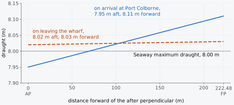
Figure 6.1 Draughts of the Steel Flower on arrival at Port Colborne and on leaving the wharf, against the Seaway maximum of 8.00 m, from the report of the Transportation Safety Board of Canada1. The draught axis is enlarged.
Chapter 5 dealt mostly with heel. A mass moved along the ship, or loaded or discharged away from the centre of flotation, changes the trim, and the draughts at the two ends then determine whether the ship can enter a lock and whether its propeller stays immersed. In this chapter we will calculate these draughts after a change of loading and for a complete loading condition, starting from the marks on the hull and using the equivalent even-keel draught of Chapter 3 and the moment to change trim one centimetre of Chapter 4. At the end we will look at the longitudinal stability of an intact ship, which is very large, and at the few cases in which it can still matter.
In this chapter
By the end of this chapter you will be able to:
- reduce draught-mark readings to the perpendiculars, and find the draught at F and the displacement;
- compute the change of trim and the end draughts when a mass is moved, loaded or discharged;
- find where to load a mass without changing one end draught;
- decide whether moving weight can bring a ship within a draught limit, and otherwise find the least discharge;
- find the trim of a loading condition from its weight table, and judge when the hull must be solved instead.
What it assumes. You need the axes and trim of Sec. 1.3 and the TPC of Sec. 3.4.2. From Sec. 4.10 you need MCT 1 cm and the turning of a slightly trimmed ship about F.
A first reading. Sections 6.1 to 6.4, 6.5.1 to 6.5.3 and 6.5.6 carry the main thread. Sections 6.5.4, 6.5.5 and 6.6, on the second trim correction, the change of trim with the density of the water and longitudinal stability, can wait for a second reading. Table 6.3, which closes the technical sections, collects the signs and conditions of the main thread and belongs to the first.
6.1 Trim and the draughts
6.1.1 Draught at any point of a trimmed ship
With the conventions of Sec. 1.3, the draughts and are measured at the after and forward perpendiculars, and the trim is , positive when the ship is down by the stern. The trim angle is given by , where is the length between perpendiculars, and lengths along the ship are measured forward from the AP. The three reference hulls of Chapter 1 have a straight keel with no designed drag, so at even keel the draughts at the two ends are equal.
Trim is stated as the length rather than as the angle. The draughts are what the marks show and what a lock or a berth limits, and an angle of trim means different draughts in ships of different lengths: an angle of 0.47° is a trim of 1 m in the Series 60 ship, 121.92 m long, and of 2.46 m in a ship 300 m long. For this reason the moment that changes the trim is tabulated per centimetre of trim, not per degree2.
A ship that is not bent has a straight keel, and the draught at any point between the perpendiculars lies on the straight line joining and . At a distance forward of the AP,
The deepest point of a straight keel is therefore at one of its ends, at the stern when the ship trims by the stern and at the bow when it trims by the head. A ship that is hogged or sagged has a curved keel and a midship draught that differs from the line through the end draughts, and Sec. 3.6.1 showed how the midship marks are used to allow for it. In this chapter the hull is taken as straight.
6.1.2 Reading the draught marks
As we saw in Sec. 1.2.6, the draughts of a ship in service are read from draught marks painted near the ends of the hull. The marks usually show keel draughts, measured from the underside of the keel, and they stand a short distance from the perpendiculars. The draughts of hydrostatic data may be measured from the moulded baseline or from the bottom of the keel, and the marks themselves may refer to another baseline, so the user has to know which2. Design data use moulded draughts at the perpendiculars, and two corrections are then needed before the readings can be used with them2,3.
The first correction is for the position of the marks. Let the aft marks stand at and the forward marks at , and let their readings, each the mean of the port and starboard marks, be and . The two readings lie on the straight waterline of Eq. (6.1), so the trim between the perpendiculars is the trim between the marks scaled up to the length ,
and the draughts at the perpendiculars follow by moving along that line from each set of marks to its perpendicular,
The corrections are small, but they grow with the trim and with the distance of the marks from the perpendiculars4. The second correction is for the keel, and it is needed when the hydrostatic data are moulded. A keel draught exceeds the moulded draught by the thickness of the keel plate, or by the depth of a bar keel, and this thickness is subtracted from both draughts2.
6.1.3 Draught at the centre of flotation
Section 1.6 defined the centre of flotation F, the centroid of the waterplane, and Sec. 4.10.1 showed that a ship trimming slightly at constant displacement turns about F, which for this reason is known as the tipping centre4,5. The draught at F is then the equivalent even-keel draught, the draught at which the ship would float level with its displacement unchanged, also called the true mean draught4,5. By Eq. (6.1), the draught at F is
The second form shows that the mean of the two end draughts is the draught at F only when F lies amidships. In most ships F lies a little aft of amidships6. It lies up to about 3 % of the length forward of amidships in very full forms and up to about 3 % aft in fine forms5. On the Series 60 hull, a fine form, F lies 4 to 5 m aft of amidships at its loaded draughts, 3 to 4 % of the length. When such a ship trims by the stern, the mean of the end draughts is less than the draught at F, and when it trims by the head the mean is greater (Fig. 6.2). Entering the hydrostatic table with the mean of the end draughts would then give the wrong displacement. The difference is the mass of a thin layer between the two parallel waterplanes through F and through amidships. The correction to be added to the displacement read at the mean of the end draughts is tonnes, with in metres, by the stern positive: it is negative when the ship trims by the head with F aft of amidships. In draught surveys it is called the first trim correction or the layer correction5,6. Equation (6.4) is exact for a straight waterline. While the trim is small, the draught at F is the equivalent even-keel draught, and the hydrostatic table entered there gives the displacement; at larger trims a second correction is needed.
Table 6.1 gives the hydrostatic values of the Series 60 ship from 5.2 m to 7.2 m, with the moment to change trim one centimetre. That moment is calculated from the second moment of the waterplane by Eq. (4.23), , as in most hydrostatic tables, since that value does not depend on the position of G2. With in place of , the value is strictly an approximation to the MCT 1 cm of a loaded ship and could be labelled as such. For the Series 60 ship, with G about 2.5 to 3 m above B and about 140 m, the tabulated value is about 2 % too large. Tables also differ in the form of this column. Many give the moment to change trim one metre, a hundred times MCT 1 cm, and some give a volume moment3,6, in m⁴/m. Others give a moment of force, computed from the weight instead of the mass6, so the title and unit of the column should be read before a value is used. In this hull and draught range, MCT 1 cm and TPC grow with the draught, and moves aft as the waterplane becomes fuller aft. This is a common trend, described by Attwood, rather than a rule for every hull7.
Table 6.1 Hydrostatic values of the Series 60 hull, 121.92 m between perpendiculars, in sea water ( = 1.025 t/m³), upright and at even keel. and are measured forward of the AP, and amidships is at 60.96 m; MCT 1 cm is .
| (m) | (t) | TPC (t/cm) | (m) | (m) | MCT 1 cm (t·m/cm) |
|---|---|---|---|---|---|
| 5.2 | 6087.8 | 13.49 | 59.69 | 58.32 | 74.54 |
| 5.4 | 6358.8 | 13.61 | 59.63 | 58.04 | 76.26 |
| 5.6 | 6632.3 | 13.74 | 59.56 | 57.73 | 78.22 |
| 5.8 | 6908.5 | 13.88 | 59.48 | 57.39 | 80.39 |
| 6.0 | 7187.7 | 14.03 | 59.39 | 57.02 | 82.75 |
| 6.2 | 7469.9 | 14.18 | 59.29 | 56.68 | 85.07 |
| 6.4 | 7754.9 | 14.32 | 59.19 | 56.38 | 87.24 |
| 6.6 | 8042.5 | 14.45 | 59.09 | 56.13 | 89.26 |
| 6.8 | 8332.7 | 14.57 | 58.98 | 55.89 | 91.34 |
| 7.0 | 8625.5 | 14.71 | 58.87 | 55.65 | 93.54 |
| 7.2 | 8921.0 | 14.84 | 58.76 | 55.42 | 95.84 |
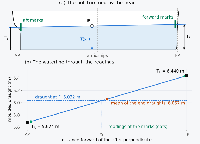
Figure 6.2 Draughts of the Series 60 ship trimmed 0.766 m by the head: (a) the hull, with heights three times as large as lengths; (b) the waterline through the readings at the marks, extended to the perpendiculars.
Example 6.1. The draughts and displacement from the marks. The Series 60 ship, 121.92 m between perpendiculars, arrives at port in sea water. Its aft draught marks stand 2.80 m forward of the AP and the forward marks 1.72 m aft of the FP, and they read keel draughts; the keel plate is 20 mm thick. The mean readings of the port and starboard marks are 5.712 m aft and 6.450 m forward. Find the moulded draughts at the perpendiculars, the trim, the draught at the centre of flotation and the displacement mass, using Table 6.1, and compare it with the value given by the mean of the end draughts.
6.2 Change of trim due to a shift of weight
6.2.1 Trimming moment and change of trim
We saw in Sec. 4.10.2 that when a mass already on board is moved a distance along the ship, G moves parallel to it through , and the ship trims until the centre of buoyancy lies under the new position of G. The moment , a moment of mass in t·m, is the trimming moment, and dividing it by the moment to change trim one centimetre, MCT 1 cm, gives the change of trim in centimetres. With the mass moved from to , the change of trim is
with in tonnes and the lengths in metres. A mass moved forward, , gives a negative change, that is, a change of trim by the head, and a mass moved aft gives a change by the stern4,6. MCT 1 cm is read at the draught at F, since the shift does not change it.
Historical note: the moment to change trim one inch
6.2.2 Change of draught at each end
As the waterline turns about F, the draught at F does not change, and the two ends move in opposite directions by amounts in proportion to their distances from F (Fig. 6.3). The AP is aft of F and the FP is forward of it, so a change of trim changes the draughts by
whose difference is the change of trim4, . A change of trim of one centimetre is thus shared between the two ends, and neither end moves by the whole centimetre. When F lies amidships, each end moves by half of it. When F lies aft of amidships, the forward draught changes more than the aft draught. In the Series 60 ship in its departure condition, with F at 56.43 m, each centimetre of trim moves the stern by 0.46 cm and the bow by 0.54 cm. The mean of the two end draughts then changes by although the displacement has not changed. For this reason the change of trim should not be divided equally between the two ends7, even though the error of doing so is minor for a small change of trim.
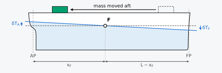
Figure 6.3 A mass moved aft, with the waterline turning about F. Schematic, with the trim enlarged and heights three times as large as lengths.
Predict 6.1. The Series 60 ship displaces 7707 t and floats level, with F at 56.43 m forward of the AP. A 60 t item of deck cargo is moved aft, from 105.68 m to 20.90 m forward of the AP. Decide whether the mean of the two end draughts changes, and if so in which direction, before you work through Example 6.2.
Example 6.2. Moving deck cargo aft. The Series 60 ship displaces 7707 t and floats level in sea water. A 60 t item of deck cargo is moved aft, from 105.68 m to 20.90 m forward of the AP. Find the change of trim and the new draughts at the perpendiculars, using Table 6.1.
Animation 6.1 shows the Series 60 ship as a mass travels slowly along its deck from forward to aft and back. The waterline turns about F, and the draught there changes by less than 1 cm while the two ends rise and fall by about a metre.
Animation 6.1 The Series 60 ship at its departure displacement while 200 t moves along the deck between 100 m and 20 m forward of the AP, each frame an equilibrium of the hull. Above, the hull, heights three times as large as lengths, with the waterline turning about F; below, the draughts at the perpendiculars and at F, solved on the hull (solid) and by Eqs. (6.5) and (6.6) (dashed). The ends rise and fall by about a metre while the draught at F changes by less than 1 cm.
6.3 Change of trim due to adding or removing weights
6.3.1 Sinkage and change of trim
When a mass is loaded, the ship sinks as well as trims. Section 3.4.4 showed how to separate the two effects. A mass placed on the vertical through F makes the ship sink bodily, without trim, by
Moving the mass from F to its actual position at then trims the ship as in Sec. 6.2, by
by the stern when the mass lies aft of F4,6. With the two changes added (Fig. 6.4), the draughts at the ends change by
A mass discharged is entered as negative. The ship then rises, and it trims by the stern if the mass was taken from forward of F and by the head if it was taken from aft of F. For several masses loaded and discharged together, their sum gives the sinkage and the sum of their moments about F gives the change of trim, usually set out in a table with a column of masses and a column of moments4,5. TPC, and MCT 1 cm are taken at the initial draught when the total mass is small. When it is not, they are taken at the draught midway between the initial and final draughts at F4, or the whole condition is worked again from its weight table.
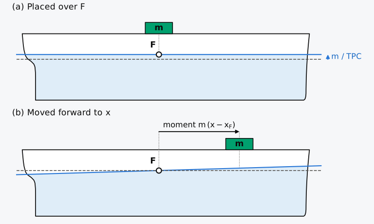
Figure 6.4 A mass loaded forward of F, in two steps: (a) placed over F, it sinks the ship bodily by m/TPC; (b) moved forward to x, it trims the ship about F. Schematic, with sinkage and trim enlarged and heights three times as large as lengths.
Example 6.3. Loading deck cargo forward. In its departure condition the Series 60 ship displaces 7707 t and floats level in sea water at 6.366 m, the draught that Table 6.1 gives for this displacement. The ship loads 150 t of deck cargo centred 95.00 m forward of the AP. Find the new draughts at the perpendiculars, using the table.
6.3.2 Loading without changing the draught at one end
A ship sometimes has to load while one of its draughts is held at a limit. A ship at a berth or in a channel whose depth limits the stern, for example, may load only where the extra mass leaves the aft draught unchanged4. The sinkage deepens both ends, and the change of trim then has to lift the stern as much as the sinkage lowers it. Extended to any point, Eq. (6.8) gives the change of the draught at a point caused by a mass loaded at as . Setting this change to zero gives the position at which the mass leaves the draught at unchanged2,
The mass and the point lie on opposite sides of F. For the aft draught, , the mass goes forward of F, and for the forward draught, , it goes aft of F4,5. The position does not depend on the mass, as long as the mass is small enough for TPC and MCT 1 cm to stay constant. With MCT 1 cm from and , the right-hand side of Eq. (6.9) is , the square of the radius of gyration of the waterplane about F. It is for a box, for the Wigley hull and about 741 m², or (27.2 m)², for the Series 60 ship in its departure condition. For this ship the changes of the two end draughts are straight lines in the position of the mass, and each crosses zero at one of the two positions (Fig. 6.5).
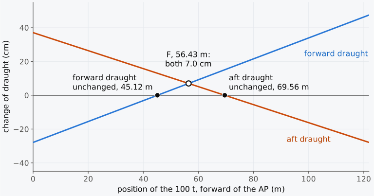
Figure 6.5 Change of the draughts at the perpendiculars when 100 t is loaded at a position along the Series 60 ship in its departure condition, by Eq. (6.8).
Predict 6.2. The Series 60 ship in its departure condition is to load 100 t without changing the aft draught. Decide whether the mass should go forward or aft of F, and estimate how far from F, before you read Example 6.4.
Example 6.4. Loading without sinking the stern. In its departure condition the Series 60 ship displaces 7707 t and floats level in sea water at 6.366 m, the draught that Table 6.1 gives for this displacement, with TPC = 14.30 t/cm, = 56.43 m and MCT 1 cm = 86.87 t·m/cm. The ship is to load 100 t without changing its aft draught. Find where the mass must be placed and the new forward draught.
6.3.3 Loading or discharging to required draughts
A more general problem is to finish loading at given draughts, for example level at a given draught. Two quantities are then fixed, the change of the draught at F and the change of trim, and two masses can be found, or one mass and its position. With masses and loaded at and , the sinkage and the change of trim give two equations,
Example 6.5. Finishing level. During loading in sea water, the Series 60 ship floats at 6.20 m aft and 5.95 m forward. 300 t of cargo remains to be loaded, in hold 2, centred 91.28 m forward of the AP, and in hold 4, centred 56.03 m forward of the AP. Find how much should go into each hold for the ship to finish level, and its final draught, using Table 6.1.
6.4 Draught limits
The draughts of a ship have limits in both directions. The forward draught has to be enough to keep the bow from pounding in a seaway, and the aft draught enough to keep the propeller immersed, allowing for the fuel and stores used on the voyage2. Loading is usually planned to finish with the ship trimmed by the stern4. The International Convention for the Safety of Life at Sea, 1974 (SOLAS), asks that the stability information supplied to the master give the maximum permissible trim against draught, within which the ship meets its stability requirements8.
6.4.1 The deepest draught and the draught at F
Locks, canals, channels and berths set an upper limit on the draught of the ships that use them, and the limit applies to the deepest point of the ship. For a straight keel with nothing projecting below it, that point is the deeper of the two ends. A ship that is down by the head can bring its bow up by moving weight aft, and the stern then goes down. The draught at F does not change meanwhile, and one end of the ship is always at least as deep as the draught at F. Moving weight on board can therefore bring both ends within a limit only if the draught at F is already within it, and at best it leaves the ship level at that draught.
Within this small-trim model, when the draught at F exceeds the limiting draught , mass has to come off. The least mass that will do is tonnes, with the draughts in metres, taken off over F and with the remaining weight moved to bring the ship level. Discharging from one end only, with nothing moved on board, usually needs more, because the discharge must then also supply the trimming moment. The ship is not left level, and with the deeper end at the limit, the draught at F ends below it.
Example 6.6. A draught limit at a lock. The Series 60 ship arrives at a lock in sea water drawing 6.10 m aft and 6.62 m forward. The lock admits no ship drawing more than 6.30 m at any point. (a) Decide whether the ship can pass by moving cargo on board. (b) Find the least mass that must be discharged. (c) Find the mass that must be discharged from hold 1, centred 105.68 m forward of the AP, if no other cargo is moved, and the draughts after it. Use Table 6.1.
6.4.2 Projections below the keel, list and squat
The navigational draught (Sec. 1.2.3) fixes the depth of water that a ship needs2. With projections below the keel, the attitude that gives the least navigational draught is in general not level. Let projections reach below the keel at , aft of F, and at , forward of F. When weight is moved on board, the draught at F stays fixed, and the navigational draught is least when the ship draws equally at the two, . By Eq. (6.1) this needs a trim
by the stern when the forward projection is the deeper2. The waterline then runs parallel to the line joining the lowest points of the two projections, and the least navigational draught is the draught at F plus the depth of that line below the keel at F. This holds provided neither end of the keel is then deeper than the projections. The trim lowers one end of the keel, and when the projection on that side lies well inside the perpendicular, that end can become the deepest point, so the keel at that end is checked as well.
Suppose, for example, that the Series 60 ship in its departure condition, level at 6.367 m as solved on the hull, with F at 56.43 m and MCT 1 cm = 86.88 t·m/cm read from Table 6.1 at that draught, had propeller tips 0.30 m below the keel at 4.0 m forward of the AP and a sonar dome reaching 0.60 m below it at 112.0 m. Level, the ship would draw 6.967 m at the dome. Trimmed 0.339 m by the stern, which needs a trimming moment of 2942 t·m, it would draw 6.813 m at both, 15.4 cm less, while the keel at the AP would be at 6.524 m.
A list also deepens a ship. When the ship lists through a small angle about the centreline at the waterline, a point of its low side at a half-breadth and a height above the keel goes to a depth . In a box the deepest point is the bilge corner4,5, at , so the draught grows by nearly . In a ship with a rounded bilge the deepest point at a small list lies at or near the outer edge of the flat of keel, whose half-breadth takes the place of . The flat of keel of the Series 60 ship extends 5.77 m to each side of the centreline amidships, so at 6.367 m a list of 1° adds 10.0 cm to the ship’s deepest draught, against 14.1 cm for a box of its breadth. That is nearly the 11 cm by which the Steel Flower was too deep. Wide ships are the most exposed, since a small list can put their bilge on the bottom4.
Under way in shallow water a ship sinks and trims as well. The water it pushes aside flows back faster beneath the bottom, and the fall in its pressure draws the ship down. This squat reduces the clearance under the keel below its static value2,4. Full forms usually squat most at the bow and fine forms at the stern4. Squat grows about as the square of the speed through the water and in proportion to the block coefficient4. A short-cut estimate of the greatest squat, from about 600 results measured on ships and models, is in metres in open water 1.1 to 1.4 times as deep as the draught, where is the speed through the water in knots4. In a confined channel such as a river or a canal, where the immersed midship section of the ship takes 10 to 26.5 % of the cross-section of the channel, the estimate is twice as large4. For the Series 60 ship, with = 0.60, at 6 knots (3.09 m/s) it gives 0.22 m in open water and 0.43 m in a channel. These exceed both the 15.4 cm gained by trimming and the 10.0 cm added by a 1° list, so the clearance that a ship needs under way has to allow for squat as well as for its static draught.
6.4.3 The Steel Flower
With the draught at F we can now return to the Steel Flower. On arrival at Port Colborne it was drawing 7.95 m aft and 8.11 m forward, a trim of 0.16 m by the head on a length of 222.48 m. The report does not give the ship’s centre of flotation, but Eq. (6.4) gives the draught at F for any position of F,
This is the draught at which the ship would have floated if the crew had made it exactly level by moving weight on board. It reaches 8.00 m only for , with F about 69.5 m forward of the after perpendicular, nearly a fifth of the length aft of amidships. The centre of flotation of a ship lies much nearer amidships than that, usually within about 3 % of the length5, and on the Series 60 hull 3 to 4 % aft. Even with F anywhere within 5 % of the length from amidships, the Steel Flower would have floated level at a draught between 8.022 m and 8.038 m (Fig. 6.6). It left the wharf drawing 8.02 m aft and 8.03 m forward, as level as the readings can show and within that range of draught. To reach 8.00 m, the ship would have had to lose 2.2 to 3.8 cm of draught at F. This would have meant discharging 2.2 to 3.8 times its tonnes per centimetre from over F, besides moving weight to keep it level. Unless the centre of flotation lay unusually far aft, moving weight on board could not have brought the ship to 8.00 m.
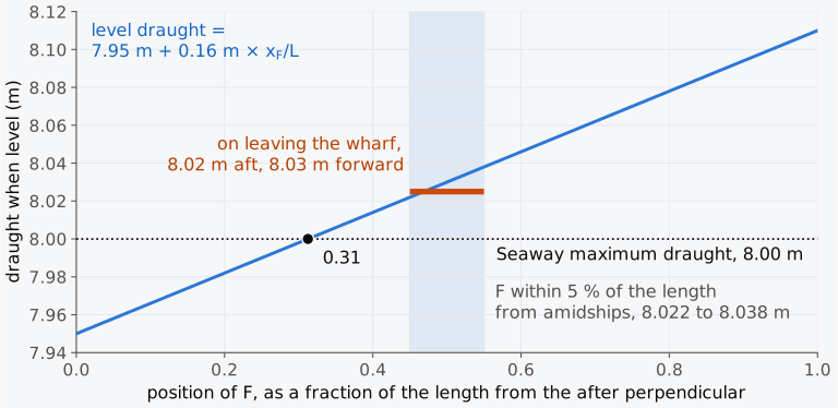
Figure 6.6 The draught at which the Steel Flower would have floated level, against the position of its centre of flotation, from the draughts on arrival at Port Colborne1.
6.5 Trim of a loading condition
6.5.1 From the weight table to the draughts
The methods of Secs. 6.2 and 6.3 change a known condition step by step. A loading condition can also be worked from the beginning. Its weight table gives the displacement and the position of G, and KG. The hydrostatic table, entered with the displacement, gives the draught at which the ship would float level, , and at that draught , and MCT 1 cm. If equals , the ship floats level at that draught, as the Series 60 ship does in its departure condition, with = 59.21 m at 7707 t. Otherwise G and B are a distance apart along the ship, the trimming moment is , and the ship trims about F until its centre of buoyancy lies on the vertical through G. In ship axes that vertical leans with the trim3. When the ship trims by the stern through an angle (Fig. 6.7), the point of that vertical at the height of B lies aft of G, while the centre of buoyancy moves aft from B, its position in the level ship, to , through (Sec. 4.10.1). The two points coincide when
that is, when . With and from Eq. (4.22), the trim, in metres, is
by the stern when G lies aft of B2,4. The draughts at the ends follow from Eq. (6.4), and .
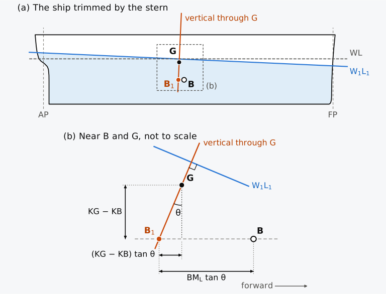
Figure 6.7 B on the vertical through G in a ship trimmed by the stern: (a) the Series 60 ship, heights three times as large as lengths; (b) the construction near B and G, not to scale.
Because the vertical through G leans in ship axes, and G of a trimmed ship do not have the same . Before taken from a program is compared with , which is always measured in the ship, the axes of the program’s output are checked, since some programs give in axes that stay level as the ship trims3.
Equation (6.11) can be turned round. When the draughts of a ship are read, gives the displacement, and the trim gives the longitudinal position of G,
which is how the longitudinal centre of gravity of a ship afloat is found from its draughts, for example in the inclining experiment2,6.
Example 6.7. The trim of the arrival condition. On arrival the Series 60 ship displaces 7236 t in sea water, with = 60.22 m forward of the AP and KG = 6.13 m. Find the trim and draughts, using Table 6.1. Find the trim again with MCT 1 cm calculated with , taking KB = 3.24 m at this draught, and compare the two trims.
6.5.2 Large changes of loading
Equations (6.5) to (6.11) rest on two approximations: that the trimmed waterline passes through the centre of flotation of the level waterline, and that MCT 1 cm does not change as the ship trims2. Both are good for small trims. As the trim grows, the immersed end and the emerged end are no longer wedges of the same shape, F moves along the waterplane, and the waterplane itself changes. Moore2 advises calculating the equilibrium directly from the hull when the draughts must be accurate, when the trim exceeds about 1/150 of the length, or when the trim changes the shape of the waterplane markedly. For the Series 60 ship, 1/150 of the length is 0.81 m. As can be seen from Fig. 6.8, at the departure displacement a trimming moment of 12,000 t·m trims the hull 1.44 m by the head, 6 cm more than Eq. (6.11) gives with the tabulated MCT 1 cm, but 1.38 m by the stern, within 1 cm of it. The two directions differ because the hull above and below the waterline is shaped differently at the bow and at the stern. With the hull trimmed 1.44 m by the head, F lies at 57.64 m and MCT 1 cm, computed as from the trimmed waterplane, is 82.4 t·m/cm. Trimmed 1.38 m by the stern, F lies at 55.48 m and MCT 1 cm is 90.7 t·m/cm, against 56.43 m and 86.9 t·m/cm level. As the trim grows, the ship therefore becomes easier to trim further by the head and harder to trim by the stern. The agreement within 1 cm by the stern is a coincidence. By the stern, MCT 1 cm grows with the trim, and this offsets the error of Table 6.1, whose MCT 1 cm, taken with in place of , is about 2 % too large.
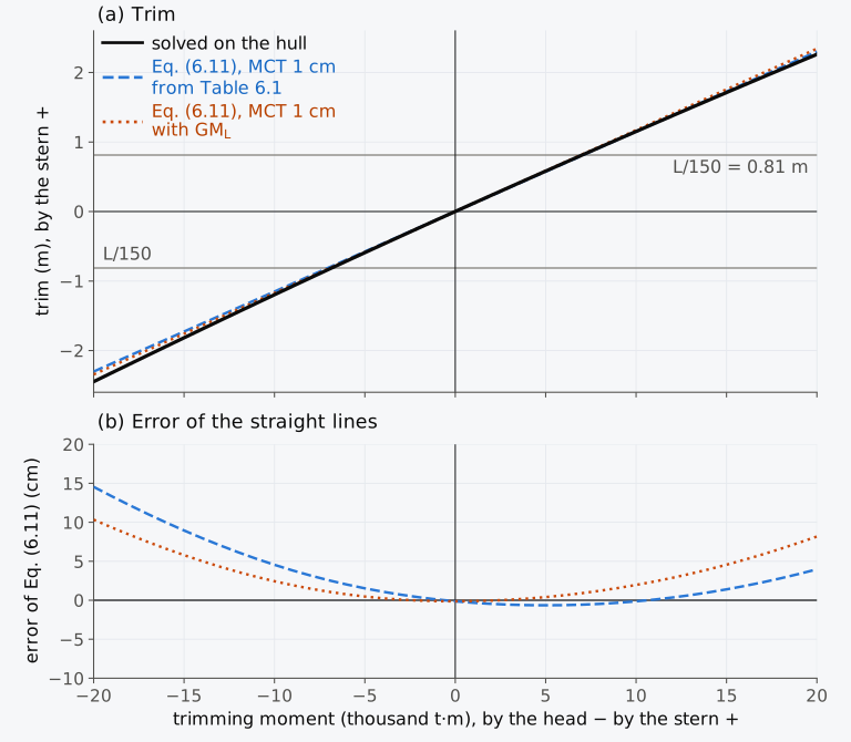
Figure 6.8 Trim of the Series 60 ship at its departure displacement against the trimming moment: (a) solved on the hull, and by Eq. (6.11) with two values of MCT 1 cm; (b) the error of the straight lines.
The incremental method of Sec. 6.3 makes a further approximation. It uses the hydrostatic values of the initial condition for the whole change, which fails when the displacement changes much, and it is acceptable only for small changes from a condition without a large initial trim2. Working from the weight table removes that error, because the hydrostatic values are those of the new displacement, but Eq. (6.11) still assumes a small trim.
When the Series 60 ship discharges all 4300 t of its cargo from the departure condition (Table 6.2), 3407 t remains, with = 55.27 m and KG = 6.12 m. With the TPC, and MCT 1 cm at the level draught of 6.366 m that Table 6.1 gives for the departure condition, the five holds give a sinkage of cm and a moment about F of 25,352 t·m. Equations (6.7) and (6.8) then give the first row of the table, with the aft draught 31 cm too deep. The hull at 3407 t has = 3.139 m, = 60.07 m, = 59.95 m and MCT 1 cm = 63.74 t·m/cm. With these values, Eq. (6.11) gives a trim of m, within 2.3 cm of the hull at both ends, although the trim is 2.1 % of the length.
Table 6.2 Draughts of the Series 60 ship after discharging all its cargo from the departure condition, by three methods.
| Method | (m) | (m) | (m) |
|---|---|---|---|
| Incremental, with the hydrostatic values of the departure condition (Sec. 6.3) | 4.710 | 1.792 | 2.918 |
| From the weight table, Eq. (6.11) at 3407 t | 4.401 | 1.835 | 2.566 |
| Solved on the hull | 4.399 | 1.812 | 2.587 |
When the trim itself is large, neither approximation can be relied on, and loading software finds the equilibrium of the hull directly. One method repeats the incremental step of Sec. 6.3 from the current waterline. At each step the hull is integrated below that waterline. The difference between the weight and the buoyancy, divided by TPC, then corrects the draught at F, and the difference between their moments about F, divided by MCT 1 cm, corrects the trim, both taken for that waterline2,3. For typical cases the iteration converges in about three steps2. A program must still check its force and moment residuals rather than stop after a fixed number of steps. Taken about F, the two corrections do not disturb each other to first order. A change of trim about F leaves the displaced volume unchanged, because the waterplane has no first moment about F, and a parallel sinkage adds a layer centred on F, which has no moment about F. This is also why a loaded mass was first placed over F in Sec. 6.3.1.
6.5.3 Exploring trim (Explorer 6.1)
In Explorer 6.1 you can float the Series 60 ship level at a displacement mass of your choice, then move a mass along its deck or load it at a chosen position. The new draughts are found in three ways: by the incremental method, from the new weight table with Eq. (6.11), and on the hull itself. The trim of the hull is compared with . For a mass moved on board the first two agree, because the displacement does not change. Try moving 200 t from the bow to the stern at the departure displacement, and then loading 600 t near the bow with the ship at 4000 t.
6.5.4 Displacement at a large trim
A large trim also affects the displacement found from the draughts. Equation (6.4) treats the waterplane as unchanged as the ship trims about F, and the volume brought in at one end then equals the volume taken out at the other. That is exact only for wall-sided ends. When the waterplane grows with the draught, as it does in most ships, the immersed end gains a little more volume than the emerged end loses. The first-order terms cancel about F, and what remains is of the second order in the trim angle. A strip of waterplane of breadth at a distance from F is immersed by , and the extra volume from the flare of its sides is per unit length. Summed over the waterplane, this is , where is the longitudinal second moment of the waterplane about F. With and , the extra displacement is
in tonnes, with and in metres and the change of MCT 1 cm per metre of draught. It is always added when MCT 1 cm increases with the draught. In draught surveys it is called the second trim correction, with the change of MCT 1 cm taken over one metre of draught4,9. The derivation above evaluates that change at the draught at F, so here the metre is centred on it. For the arrival draughts of Example 6.1, a trim of 0.766 m by the head with the draught at F 6.032 m, Table 6.1 gives MCT 1 cm = 77.55 t·m/cm at 5.532 m and 88.57 t·m/cm at 6.532 m. The extra displacement is then
so that the displacement mass from the marks becomes t, against 7236 t in the weight table.
6.5.5 Change of trim with the density of the water
Section 3.5.2 showed that a ship moving from sea water into fresher water sinks, because its unchanged mass needs more volume. The extra volume is a thin layer at the waterline, and its centroid lies close to the centre of flotation. Unless F lies on the vertical through B, the layer moves B along the ship, while G does not move, so the ship also trims. With a layer of volume added to the volume , B moves through
towards F, and the ship trims through
in metres, by the head when F lies aft of B, with MCT 1 cm taken in the new water4,5.
Predict 6.3. The Series 60 ship floats level in sea water with F 2.78 m aft of B. The ship moves into fresh water. Decide whether it will trim by the head or by the stern.
Example 6.8. From sea water into fresh water. In its departure condition the Series 60 ship displaces 7707 t, with = 59.21 m, and floats level in sea water at 6.366 m, the draught that Table 6.1 gives for this displacement. The ship moves up a river into fresh water of density 1.000 t/m³. Find the new draughts, using the table.
6.5.6 Trim calculator (Calculator 6.1)
Calculator 6.1 finds the draughts of the Series 60 ship after loading, discharging and moving masses, starting from its draughts at the perpendiculars. It works the change by the incremental method of Sec. 6.3, with TPC, and MCT 1 cm read at the initial draught at F or at a draught you choose, and MCT 1 cm is that of Table 6.1, . For comparison, the new condition is also worked from the weight table: the displacement and are found from the initial draughts by Eqs. (6.4) and (6.12), the masses are added, and the trim follows from Eq. (6.11). A difference of more than 3 cm at an end triggers a prompt to examine the approximations. This is a teaching threshold, not an accuracy tolerance; agreement between two approximations does not establish their accuracy. The locked presets repeat three of the worked examples, and “Your own loading” accepts any list of masses. A change that would take the displacement outside Table 6.1, or either end draught below the keel or above the deck, is refused.
6.6 Longitudinal stability
6.6.1 The longitudinal metacentric height in service
Section 4.10.1 showed that the longitudinal metacentric radius of a ship is of the order of its length. For the Series 60 ship in its departure condition, is 135.0 m, against a transverse GM of 0.659 m, both without the free surfaces. A moment of mass of 88.6 t·m heels the ship through 1°. Applied as a trimming moment, it changes the trim by 1.04 cm, an angle of 0.0049°, since the ship’s MCT 1 cm by Eq. (4.22) is 85.3 t·m/cm. An intact ship of ordinary form has a large initial restoring margin in pitch in calm water. The practical hydrostatic question is usually its draughts and trim under the moments that act on it2,6.
Like the transverse GM, the longitudinal metacentric height can be measured on the ship, by moving a known mass a distance along the ship and reading the change of trim, , that it causes4. By Eq. (6.5) with MCT 1 cm from Eq. (4.22),
with in metres. In practice the trim is used the other way round, to find from the draughts by Eq. (6.12).
6.6.2 Free surface and trim
A slack tank reduces the longitudinal stability as it reduces the transverse stability. The argument of Sec. 5.3.1, with the tank inclined along its length instead of across it, gives a virtual rise of G of
where is the density of the liquid in the tank and is the second moment of the free surface of a rectangular tank of length and breadth about its transverse axis. The correction has the form of the transverse free surface correction, but it is measured against , which is of the order of the length. For the starboard fuel tank FO3S of the Series 60 ship, the rectangular tank of Table 5.1, 23.2 m long and 6.9 m wide, m⁴, and with fuel of density 0.98 t/m³ the virtual rise is m. That is 0.68 % of the departure of 135.0 m, and it reduces MCT 1 cm by that fraction, whereas FO3S takes 12 % of the transverse GM. The value of holds only while the surface stays clear of the top and the bottom of the tank. In a tank of length and depth , filled to a fraction of its depth, the surface reaches the top when . FO3S holds 175 t of its 191.4 t at departure, so = 0.914, , and its surface reaches the top of the tank at a trim of about 1.10 m. For ships with normal tankage the effect on trim is small and usually ignored. It matters in vessels without extensive transverse subdivision, such as some river barges, and in ships with large damaged spaces2.
6.6.3 Loss of longitudinal stability
A ship comes near the limit of its longitudinal stability only when much of the waterplane is lost or when the ship is supported at one point. A compartment at one end that floods removes waterplane far from F, where it contributes most to , and also adds a large trimming moment. A ship touching the bottom or a dock block at one end is supported there, and its stability then depends on the reaction at the support. In some unusual forms, among them catamarans and offshore platforms, the longitudinal stability need not exceed the transverse by a wide margin, and each such design is assessed on its own6. A catamaran’s separated hulls greatly increase its transverse waterplane moment. Their separation does not give the same increase in the longitudinal moment; the longitudinal stability must be calculated from the actual hull geometry and loading10. Trim also changes as a ship heels, because B moves along the ship as well as across, and stability calculations at large angles allow for this.
The signs, units and conditions of the main relations of Secs. 6.1 to 6.5 are listed in Table 6.3.
Table 6.3 Signs, units and conditions of the main relations of trim in Secs. 6.1 to 6.5.
| Quantity or relation | Sign and unit | Condition |
|---|---|---|
| Trim, (Sec. 6.1.1) | m, positive by the stern | draughts at the perpendiculars; mark readings reduced by Eqs. (6.2) and (6.3) |
| Trim angle, (Sec. 6.1.1) | the sign of | between perpendiculars; trim is stated as , not as |
| Draught at , Eq. (6.1) | m, forward of the AP | a straight hull, neither hogged nor sagged |
| Draught at F, Eq. (6.4) | m; gives the displacement | exact for a straight waterline; the displacement read at it needs a small trim; at larger trims, add Eq. (6.13) |
| , with TPC and MCT 1 cm (Sec. 6.3.1) | m, measured forward of the AP | read at the draught at F; for a large mass, midway between the initial and final draughts |
| MCT 1 cm, from Eq. (4.23) | t·m/cm; other tables may give the moment to change trim one metre, or a moment of force | in place of , which makes it about 2 % too large for the Series 60 ship (Sec. 6.1.3) |
| Mass moved, Eq. (6.5) | cm; by the head (negative) for a mass moved forward | small trim (Sec. 6.5.2) |
| End draughts, Eq. (6.6) | cm, opposite in sign; equals | the waterline turns about F; equal shares only when F lies amidships |
| Mass loaded, Eqs. (6.7) and (6.8) | cm; by the stern for a mass aft of F; a mass discharged is negative | small mass, otherwise the values midway through the change (Sec. 6.3.1) |
| Trim of a loading condition, Eq. (6.11) | m, by the stern when G lies aft of B | small trim, values at the new displacement; a solution on the hull beyond about (Sec. 6.5.2) |
6.7 Trim in industry today
This section describes practice in 2026.
Loading computers. Stability instruments approved under Part B of the International Code on Intact Stability, 2008 (IS Code) present, for each loading condition, the trim and list and the draughts at the draught marks and at the perpendiculars11. To approve an instrument, the Administration is given the positions of the perpendiculars and, if appropriate, the method used to derive the draughts at the actual positions of the marks11. The Code recommends that the hydrostatic and stability curves be prepared for the range of trim of the operating loading conditions, taking into account the change of trim with heel, that is, with the trim free11. Among the contents it recommends for the stability booklet are hydrostatic curves or tables and cross curves of stability calculated on a free-trimming basis, for the ranges of displacement and trim expected in normal operation11. Where curves of limiting GM are used, the IS Code requires them to cover the full range of operational trims, unless the Administration agrees that the effect of trim is not significant11. Modern software finds the equilibrium of the hull directly, with the properties of the hull computed for the trimmed waterline instead of read from an even-keel table2. Such a program is approved against the tolerances of the IMO guidelines MSC.1/Circ.1229 and of IACS UR L5 (Sec. 2.10.2). For the draughts, compared with those of the approved stability information or of the approving authority’s model, the Circular prints the tolerance as 1 % / 5 cm max12. UR L5 gives the same two values and allows the greater of them13, which for the Series 60 ship is 6 cm at about 6 m, and 5 cm at any draught up to 5 m. After the discharge of Table 6.2, the draughts given by Eq. (6.11) at the new displacement are within that tolerance, but those of the incremental method are not.
Draught limits. On the St. Lawrence Seaway14 the maximum draught in both the Montreal to Lake Ontario section and the Welland Canal is 8.08 m in 2026, 8 cm more than the limit the Steel Flower faced in 1996. Ships with a draught information system approved by a member of IACS may be allowed 7 cm more under the Seaway Handbook15. The Seaway also refuses ships trimmed by the stern more than 4.57 m without special permission15. The Panama Canal Authority applies its maximum transit draught to the deepest point of the ship in tropical fresh water. Its notice to shipping of 2026 warns that the passage into the fresh water of the canal often trims large ships 7.5 to 10 cm by the head16, the effect calculated in Example 6.8. Ports also limit trim for safe handling. The Port of Port Hedland, for example, sets a minimum forward draught and a maximum trim by the stern for ships arriving at its berths, such as 0.7 % of the length overall for ships of more than 80,000 tonnes deadweight17.
Draught surveys. The reduction of mark readings to the perpendiculars and the first and second trim corrections of Secs. 6.1.3 and 6.5.4 are standard steps of a draught survey. Wawrzyński9 compared the usual second trim correction with the displacement computed directly from the hull of a bulk carrier 176.65 m long. The errors stayed below 0.5 times the TPC up to a trim of 3 m, but at a trim of 6 m by the stern they spread over nearly 5 times the TPC. He recommended that shipyards supply tables of second trim corrections computed from the hull.
Bow height. The International Convention on Load Lines sets a minimum bow height, measured at the forward perpendicular from the waterline of the summer freeboard at the designed trim18. Trim enters the rules for that reason as well as through the draught. In 2009 the Norwegian general cargo ship Langeland foundered in rough weather in the Kosterfjord off the west coast of Sweden, with the loss of all six crew. The investigators found that the ship’s stability calculations had not taken account of trim, and that it had too little reserve buoyancy forward. Requirements on the maximum trim by the head and the minimum bow height of a fully loaded ship had applied when the Langeland was built in 1971 and were removed in 1987, and the investigators recommended that they be reintroduced19.
Trim and fuel. The guidelines of the International Maritime Organization for the Ship Energy Efficiency Management Plan, adopted by resolution MEPC.395(82), state that for any draught there is a trim that gives the least resistance. They advise that trim and ballast be planned with this in mind where design and safety allow20. Model tests and computations of fluid flow on the KRISO container ship21 found that a trim of 0.25° by the head reduced the calm-water resistance at the design draught by 1.25 %, while a trim of 1° by the stern increased it by about 8 %. The best trim changes with the speed22, and it has to be found again for shallow water, where the flow round the hull is different23. Trim optimization is therefore offered as a service. FORCE Technology, for example, describes computations of the flow round a ship in 120 to 180 combinations of draught, trim and speed, from which the best trim for a voyage is chosen on board24. Any trim chosen for fuel must still meet the limits on stability, strength and draught.
6.8 From trim to the hydrostatic curves
Every method of this chapter needed the hydrostatic values of the ship at its draught: the displacement, TPC, the centres of buoyancy and flotation, and MCT 1 cm. Table 6.1 gave a few of them at intervals of 0.2 m. On board, and in the design office, they are drawn as curves against the draught, together with KB, KM, and the coefficients of form, so that any of them can be read at any draught. In Chapter 7 we will see how these hydrostatic curves are calculated from the lines of the hull and how each of them varies with the draught. We will also return to the Bonjean curves of Chapter 1, which give the displacement of a ship at a trim too large for the level curves to be trusted.
Summary
- The draught at a distance from the AP of a trimmed ship is ; the deepest point of a straight keel is at one end.
- Draught marks usually read keel draughts at positions near the perpendiculars. The readings are reduced to the perpendiculars along the straight waterline, Eqs. (6.2) and (6.3), and the keel thickness is subtracted.
- A ship trimming slightly turns about the centre of flotation F, so the draught at F is the equivalent even-keel draught, or true mean draught, and gives the displacement. The mean of the end draughts gives it only when F lies amidships.
- While the trim stays small, a mass moved along the ship changes the trim by its moment divided by MCT 1 cm. The ends move in proportion to their distances from F.
- A small mass loaded sinks the ship by and trims it by . It leaves the draught at a point unchanged when , which is when MCT 1 cm is taken from .
- Moving weight on board cannot reduce the draught at F. For a straight keel with nothing below it, if the draught at F exceeds a limit, at least tonnes must come off.
- With projections below the keel, the navigational draught is least at the trim that makes the ship draw equally at a projection aft of F and a projection forward of F, provided neither end of the keel is then deeper. A small list deepens a box by nearly , and squat deepens a ship under way in shallow water.
- For a small trim, the trim of a loading condition is , with the hydrostatic values at the displacement. It follows from B lying on the vertical through G, which in ship axes leans with the trim. Working from the new weight table accounts for a large change of displacement, but the resulting trim must still be small. Loading software can instead solve equilibrium directly on the hull, for example by repeating the incremental step about F and checking the residuals.
- A second-order correction, tonnes, improves the displacement estimate when the trim is larger; it does not replace a hull solution at arbitrarily large trim.
- A ship moving into fresher water sinks and also trims, by the head when F lies aft of B and by the stern when F lies forward of B.
- The longitudinal metacentric height of an intact ship is of the order of the ship’s length. A slack tank whose surface stays clear of its top and bottom reduces it by , which is small unless the tank is long.
Notes on the data
The Steel Flower. The ship’s length, cargo, draughts, the Seaway limit of 1996, the events in the canal and the damage are from the report of the Transportation Safety Board of Canada1. The report gives neither the ship’s hydrostatic data nor where its draughts were read. The length of 222.48 m is taken as the length between perpendiculars and the draughts as those at the perpendiculars; only affects the conclusion. The band of 5 % of the length for F is an assumption, wider than the 3 % usually taken5.
Table 6.1 and the hull solutions. The hydrostatic values are computed on the Series 60 surface by scripts/ch06_data.py, with MCT 1 cm from . “Solved on the hull” means that the equilibrium of the trimmed hull is found by direct integration of its sections below the inclined waterline, adjusting the draught and trim until the displaced mass equals the displacement and B lies on the normal to the waterline through G, without the small-trim approximations of this chapter; the method is that of Chapter 3 (ch03/scripts/inclined.py). The centre of flotation and MCT 1 cm of the trimmed hull in Sec. 6.5.2 are integrated over its inclined waterplane at the solved equilibrium. The cargo holds are those of Table 3.1, and the arrival condition is that of Exercise 3.10.
The examples. The positions of the draught marks, the thickness of the keel plate, the cargo moved, loaded and discharged, the lock of Example 6.6 and the projections below the keel in Sec. 6.4.2 are illustrative; the Series 60 hull has no projections. The half-breadth of its flat of keel, 5.77 m, is that of the surface at the baseline amidships, and the deepest draught of the listed hull is computed on the surface by scripts/ch06_data.py. A mass moved on deck at the departure or arrival displacement is taken as part of that displacement, although those loading conditions carry no deck cargo. In Examples 6.5 and 6.6 the ship’s condition is given only by the draughts; for the hull solutions it is taken as the displacement and at which the hull floats at those draughts, with KG = 6.0 m. The printouts of Exercise 6.10 give the hull solution, with the deck cargo 11.0 m above the keel, and the hydrostatic values of Table 6.1 at the displacement.
Figure 6.7. Panel (a) is the frame of Animation 6.1 in which 200 t has moved from 100 m to 20 m forward of the AP at the departure displacement, solved on the hull. In that condition is 0.037 m and is 2.06 m, a ratio of about 1 to 56, which panel (b) draws as about 1 to 4.
Explorer 6.1 and Animation 6.1. The explorer interpolates draughts solved on the hull for displacements from 3000 t to 9000 t and from 50 m to 70 m, with KG = 6.0 m; combinations at which the deck edge would go under or the keel come out of the water are not offered. The animation starts from the displacement and centre of gravity of the departure condition of Table 3.1, with 200 t of that displacement on the deck at 100 m from the AP, and solves the hull for each position of the mass.
Exercises
Under each exercise, “Show answers” opens its short answers and “Show full solution” its worked solution. Unless stated otherwise the water is sea water of density 1.025 t/m³ and the draughts are moulded draughts at the perpendiculars.
6.1 A box barge 80.00 m long has its aft draught marks 1.50 m forward of the AP and its forward marks 2.00 m aft of the FP. The marks read keel draughts of 3.42 m aft and 2.86 m forward, and the keel plate is 15 mm thick. Find the moulded draughts at the perpendiculars and the trim.
6.2 The Series 60 ship floats at 6.60 m aft and 6.20 m forward. Find the draught at the centre of flotation and the displacement mass, using Table 6.1, and its error if the mean of the end draughts were used instead.
6.3 On arrival the Series 60 ship floats at 5.674 m aft and 6.440 m forward, with its draught at F 6.032 m, where Table 6.1 gives MCT 1 cm = 83.12 t·m/cm. Find the mass of deck cargo that must be moved aft, from 91.28 m to 20.90 m forward of the AP, to bring the ship to even keel, and the draught at which it then floats.
6.4 A box barge 72 m long and 14 m wide floats level at a draught of 3.2 m, with MCT 1 cm = 60.0 t·m/cm found from its . (a) 40 t on its deck is moved 36 m aft. Find the new draughts. (b) Starting again from the level condition, find where 50 t must be loaded to leave the aft draught unchanged, and the forward draught after loading it.
6.5 The Wigley hull, 100 m long and 10 m wide, floats level at 6.25 m. Its waterplane, with , has an area of 666.67 m² and a second moment of m⁴ about its centroid amidships. (a) Find TPC, and MCT 1 cm from . (b) 60 t is loaded 20 m forward of amidships. Find the new draughts.
6.6 The Series 60 ship floats level at 6.366 m, where TPC = 14.30 t/cm, = 56.43 m and MCT 1 cm = 86.87 t·m/cm. At an intermediate port the ship discharges 120 t from hold 1, centred 105.68 m forward of the AP, and 90 t from hold 4, centred 56.03 m forward of the AP, and loads 150 t of deck cargo centred 75.00 m forward of the AP. Find the new draughts.
6.7 The Series 60 ship floats level at 6.366 m, where TPC = 14.30 t/cm, = 56.43 m and MCT 1 cm = 86.87 t·m/cm. Find where 80 t must be loaded to leave the forward draught unchanged, and the aft draught after loading it.
6.8 A ship 91.44 m between perpendiculars floats at 3.734 m forward and 4.420 m aft. Its TPC is 8.00 t/cm, the centre of flotation is 3.66 m aft of amidships and MCT 1 cm is 36.58 t·m/cm. Find where a mass of 60.96 t must be placed for the ship to float level, and its draught then. (Adapted from Attwood7.)
6.9 A bulk carrier 180 m between perpendiculars floats in fresh water at 9.30 m aft and 9.62 m forward. Its centre of flotation is 86.0 m forward of the AP and its TPC in fresh water is 38.5 t/cm. A waterway admits no ship drawing more than 9.40 m. (a) Find the draught at F, and decide whether moving ballast on board can bring the ship within the limit. (b) Find the least mass that must be discharged.
6.10 The Series 60 ship in its departure condition displaces 7707 t, with = 59.207 m. The ship loads 195 t of deck cargo centred 40.00 m forward of the AP, which brings it to 7902 t, its summer displacement mass. The stability instrument on board then prints an LCG () of 58.733 m, an LCB () of 59.139 m, both forward of the AP, and a KG of 6.013 m. It also prints a draught of 6.502 m at the centre of flotation, draughts of 6.671 m at the AP and 6.304 m at the FP, and a trim of 0.367 m by the stern. (a) Check the LCG, and check the trim and the draughts at the perpendiculars with Eq. (6.11), using Table 6.1 and interpolating to three decimals. (b) A second program prints an LCB of 58.725 m and a KB of 3.492 m for this condition. Explain why its LCB differs from the first, and why it cannot be used in Eq. (6.11).
6.11 The Series 60 ship floats at 6.52 m aft and 6.21 m forward. Find the displacement mass and the longitudinal position of the centre of gravity, using Table 6.1.
6.12 In its departure condition the Series 60 ship displaces 7707 t and floats level at 6.366 m, the draught that Table 6.1 gives for this displacement, with TPC = 14.30 t/cm, = 56.43 m and MCT 1 cm = 86.87 t·m/cm. The ship discharges all the cargo of hold 1 (271 t, centred 105.68 m forward of the AP) and hold 2 (693 t, centred 91.28 m forward of the AP), leaving 6743 t with = 54.04 m. (a) Find the draughts by the incremental method of Sec. 6.3. (b) Find them from Eq. (6.11), with the hydrostatic values at the new displacement. Solved on the hull, the ship floats at 7.681 m aft and 3.320 m forward. Comment on the results.
6.13 The Series 60 ship floats at 7.12 m aft and 5.90 m forward. Find the displacement mass with the first trim correction, by entering Table 6.1 at the draught at F, and then with the second trim correction of Eq. (6.13), taking MCT 1 cm at 0.5 m above and below the draught at F.
6.14 A ship 150 m between perpendiculars displaces 12,000 t and floats level at 8.00 m in sea water, with B at = 76.80 m and F at = 73.50 m forward of the AP. Its TPC in sea water is 24.0 t/cm, and its MCT 1 cm in sea water at the new draught will be 170 t·m/cm. The ship moves into dock water of density 1.010 t/m³. Find the sinkage, the change of trim and the new draughts.
6.15 A ship 110 m between perpendiculars displaces 6000 t. A mass of 30 t of ballast is pumped 80 m aft, and the trim changes by 0.215 m by the stern. Find the longitudinal metacentric height of the ship and its MCT 1 cm.
6.16 A river barge, a box 70 m long and 11 m wide, floats at 2.5 m in fresh water with KG = 2.8 m. Its single cargo tank, 60 m long and 10 m wide, is partly filled with oil of density 0.90 t/m³. Find the longitudinal metacentric height of the barge and its MCT 1 cm, first ignoring the free surface and then allowing for it.
6.17 A ship 150.0 m between perpendiculars floats level at 7.80 m in sea water, with F 72.0 m forward of the AP and MCT 1 cm = 160 t·m/cm. The tips of its propellers reach 0.25 m below the keel at 6.0 m forward of the AP, and its sonar dome reaches 0.85 m below the keel at 138.0 m. (a) Find the navigational draught. (b) Find the trim that makes the navigational draught least, and that draught. (c) Find the mass of ballast that must be pumped from a tank centred 125.0 m forward of the AP to a tank centred 15.0 m forward of the AP to give that trim.
6.18 Upright, the Series 60 ship would float level at 6.30 m in sea water. It arrives at a lock that admits no ship drawing more than 6.40 m, with a list of 1.5° to port. Its flat of keel extends 5.77 m to each side of the centreline amidships. Taking the list about the centreline at the waterline, (a) find the deepest draught, and (b) find the largest list with which the ship may enter the lock.
Symbols introduced in this chapter
Symbols defined in earlier chapters, among them , , , TPC, MCT 1 cm, , , , , , , and , keep their meaning.
| Symbol | Meaning | Unit |
|---|---|---|
| draught at a distance forward of the AP | m | |
| draught at the centre of flotation, the equivalent even-keel draught or true mean draught | m | |
| , | draughts read at the aft and forward marks | m |
| limiting draught of a lock, channel or berth | m | |
| , | positions of the aft and forward draught marks, forward of the AP | m |
| ; ; , | a mass loaded, discharged or moved; its position; its positions before and after a move | t; m |
| distance through which a mass is moved along the ship | m | |
| position of a point whose draught a loaded mass leaves unchanged | m | |
| , ; , | two masses loaded to reach required draughts; their positions | t; m |
| , ; , | depths below the keel of the lowest points of an aft and a forward projection; their positions | m |
| speed through the water | knots | |
| change of trim, positive by the stern | cm or m | |
| bodily sinkage | cm or m | |
| , | changes of the draughts at the perpendiculars | cm or m |
| second trim correction to the displacement | t | |
| , | volume of the layer added when the water becomes less dense; volume before the change | m³ |
| movement of B along the ship | m | |
| virtual rise of G for inclinations along the ship, from free surfaces | m | |
| second moment of a free surface about its transverse axis | m⁴ | |
| , | breadth of a strip of waterplane or of a tank; length of a tank | m |
| , | depth of a tank; fraction of its depth filled | m; – |
Corrections
Corrections to version 1.0, released on 3 November 2026, with their dates.
- 3 November 2026. Sec. 6.4 and the reference list cite SOLAS in its consolidated edition of 2024, in place of that of 2020.
- 5 November 2026. Table 6.3 and the sentence that introduces it describe the table as the main relations of Secs. 6.1 to 6.5, not every relation of the chapter; its row for Eq. (6.6) follows that for Eq. (6.5), and the route for a first reading includes it.
- 5 November 2026. Sec. 6.2.1 says that the trimming moment is a moment of mass in t·m, and Sec. 6.6.1 that the longitudinal and transverse GM it compares are both without free surfaces.
- 5 November 2026. Sec. 6.7 gives the tolerance of MSC.1/Circ.1229 on the draughts as the Circular prints it, 1 % / 5 cm max, and the greater of the two values as the reading of IACS UR L5, in place of “1 % or 5 cm, the greater” cited to both.
- 6 November 2026. Sec. 6.6.3 is headed “Loss of longitudinal stability”, in place of “When longitudinal stability matters”. Its text is unchanged.
References
- Transportation Safety Board of Canada. (1997). Marine occurrence report: Bottom contact by the bulk carrier “Steel Flower” in the Welland Canal, 28 April 1996 (Report No. M96C0022). Retrieved November 2, 2026, from https://www.tsb-bst.gc.ca/eng/rapports-reports/marine/1996/m96c0022/m96c0022.html Cited: ↑ · ↑ · ↑ · ↑ · ↑ · ↑
- Moore, C. S. (2010). Intact stability (J. R. Paulling, Ed.; Principles of Naval Architecture Series). Society of Naval Architects and Marine Engineers. Cited: ↑ p. 14 · ↑ pp. 58–59 · ↑ p. 56 · ↑ p. 59 · ↑ p. 14 · ↑ p. 58 · ↑ p. 73 · ↑ p. 57 · ↑ p. 57 · ↑ p. 57 · ↑ p. 54 · ↑ p. 56 · ↑ p. 55 · ↑ p. 55 · ↑ p. 56 · ↑ p. 55 · ↑ p. 55 · ↑ pp. 4–5 · ↑ pp. 34–35 · ↑ p. 54
- Biran, A., & López-Pulido, R. (2014). Ship hydrostatics and stability (2nd ed.). Butterworth-Heinemann. Cited: ↑ p. 180 · ↑ p. 104 · ↑ p. 177 · ↑ p. 177 · ↑ p. 351
- Barrass, C. B., & Derrett, D. R. (2006). Ship stability for masters and mates (6th ed.). Butterworth-Heinemann. Cited: ↑ p. 492 · ↑ p. 144 · ↑ p. 281 · ↑ p. 150 · ↑ pp. 148–149 · ↑ p. 151 · ↑ pp. 153–156 · ↑ p. 153 · ↑ p. 159 · ↑ pp. 159–160 · ↑ pp. 156–158 · ↑ p. 159 · ↑ pp. 189–190 · ↑ p. 191 · ↑ p. 324 · ↑ p. 324 · ↑ p. 326 · ↑ p. 327 · ↑ pp. 326–327 · ↑ p. 166 · ↑ pp. 492, 496 · ↑ pp. 375–378 · ↑ pp. 163–165
- Kemp, J. F., & Young, P. (2001). Ship stability: Notes and examples (3rd ed., rev. C. B. Barrass). Butterworth-Heinemann. Cited: ↑ p. 89 · ↑ p. 101 · ↑ p. 102 · ↑ pp. 101–103 · ↑ pp. 91–92 · ↑ pp. 96–97 · ↑ pp. 97–99 · ↑ pp. 84–85 · ↑ p. 102 · ↑ pp. 104–106 · ↑ p. 102
- Tupper, E. C. (2013). Introduction to naval architecture (5th ed.). Butterworth-Heinemann. Cited: ↑ p. 55 · ↑ p. 59 · ↑ p. 57 · ↑ pp. 56–57 · ↑ p. 57 · ↑ p. 56 · ↑ p. 60 · ↑ p. 66 · ↑ p. 86
- Attwood, E. L. (1899). Text-book of theoretical naval architecture. Longmans, Green, and Co. (Public domain.) Cited: ↑ p. 148 · ↑ pp. 143–144 · ↑ pp. 145–147 · ↑ p. 156, Example 5
- IMO. (2024). SOLAS: Consolidated edition 2024 (Sales No. IH110E). International Maritime Organization. Cited: ↑ reg. II-1/5-1.2.1
- Wawrzyński, W. (2024). The second trim correction in draught survey procedure: Accuracy analysis. TransNav, the International Journal on Marine Navigation and Safety of Sea Transportation, 18(3), 695–703. https://doi.org/10.12716/1001.18.03.25 Cited: ↑ · ↑
- Yun, L., Bliault, A., & Rong, H. Z. (2019). High speed catamarans and multihulls: Technology, performance, and applications. Springer. https://doi.org/10.1007/978-1-4939-7891-5 Cited: ↑ p. 78
- IMO. (2020). International Code on Intact Stability, 2008 (2020 ed.). International Maritime Organization. (Includes the Explanatory Notes, MSC.1/Circ.1281.) Cited: ↑ Part B, 4.1.4.1 · ↑ Part B, 4.1.6.2.3 · ↑ Part B, 3.5.1 · ↑ Part B, 3.6.7.4 · ↑ Part A, 2.1.7
- IMO. (2007). Guidelines for the approval of stability instruments (MSC.1/Circ.1229, 11 January 2007). International Maritime Organization. Cited: ↑ annex, para. 4.6 and table
- IACS. (2020). Computer software for onboard stability calculations (UR L5, Rev. 4, June 2020). International Association of Classification Societies. Retrieved October 9, 2026, from https://iacs.s3.af-south-1.amazonaws.com/wp-content/uploads/2022/02/17101147/ur-l5rev4.pdf Cited: ↑ Table 1 and Note 2
- Great Lakes St. Lawrence Seaway. (2026b). Seaway Notice No. 5 – 2026 (2 April 2026). Retrieved October 11, 2026, from https://greatlakes-seaway.com/wp-content/uploads/2026/04/notice20260402a_en.pdf Cited: ↑
- Great Lakes St. Lawrence Seaway. (2026a). The Seaway handbook: Seaway practices and procedures (2026 ed., amended March 2026). Retrieved October 11, 2026, from https://greatlakes-seaway.com/wp-content/uploads/2026/03/Seaway_Handbook_print_en2026.pdf Cited: ↑ Section 29 · ↑ Section 30
- Panama Canal Authority. (2026). Vessel requirements (OP Notice to Shipping No. N-1-2026, 1 January 2026). Retrieved November 2, 2026, from https://pancanal.com/wp-content/uploads/2021/08/N01-2026-Vessel-Requirements_BMV.pdf Cited: ↑
- Pilbara Ports. (2025). Port of Port Hedland port handbook (internal amendment table: Version 1, August 2025; website file updated 10 September 2026). Retrieved November 2, 2026, from https://www.pilbaraports.com.au/about-pilbara-ports/publications/forms-and-publications/forms-and-publications/handbook/2026/september/port-of-port-hedland-port-handbook Cited: ↑
- IMO. (2018). Load lines: Consolidated edition 2018. International Maritime Organization. Cited: ↑ Annex I, reg. 39(1)
- Accident Investigation Board Norway. (2012). Report on investigation of marine accident, Langeland LDJB3, founder in the Kosterfjord, Sweden 31 July 2009 (Marine report 2012/08). Retrieved October 11, 2026, from https://nsia.no/Marine/Published-reports/2012-08-eng Cited: ↑
- IMO. (2026). 2024 Guidelines for the development of a Ship Energy Efficiency Management Plan (SEEMP), as amended (resolution MEPC.395(82), as amended by resolutions MEPC.401(83) and MEPC.413(84)) (MEPC.1/Circ.925, 5 June 2026). International Maritime Organization. Retrieved October 11, 2026, from https://wwwcdn.imo.org/localresources/en/OurWork/Environment/Documents/MEPC.1-Circ.925%20-%202024%20Guidelines%20For%20The%20Development%20Of%20A%20Ship%20Energy%20Efficiency%20Management%20Plan%20(Seemp),%20A…%20(Secretariat)%20(1).pdf Cited: ↑ paragraphs 5.3.1 and 5.3.2
- Shivachev, E., Khorasanchi, M., Day, S., & Turan, O. (2020). Impact of trim on added resistance of KRISO container ship (KCS) in head waves: An experimental and numerical study. Ocean Engineering, 211, 107594. https://doi.org/10.1016/j.oceaneng.2020.107594 Cited: ↑
- Reichel, M., Minchev, A., & Larsen, N. L. (2014). Trim optimisation: Theory and practice. TransNav, the International Journal on Marine Navigation and Safety of Sea Transportation, 8(3), 387–392. https://doi.org/10.12716/1001.08.03.09 Cited: ↑
- Martić, I., Anušić, B., Degiuli, N., & Grlj, C. G. (2024). Numerically investigating the effect of trim on the resistance of a container ship in confined and shallow water. Applied Sciences, 14(15), 6570. https://doi.org/10.3390/app14156570 Cited: ↑
- FORCE Technology. (n.d.). Let CFD do the trim optimisation for you. Retrieved October 11, 2026, from https://forcetechnology.com/en/insights/articles/cfd-trim-optimization Cited: ↑