
At the end of the nineteenth century the metacentric height given to a ship was based largely on experience with successful ships. Attwood’s textbook of 1899 lists 15 to 18 in (0.38 to 0.46 m) for tugs and harbour vessels, 1 to 3 ft (0.30 to 0.91 m) for merchant steamers, depending on their cargo, and 3 to 3½ ft (0.91 to 1.07 m) for sailing vessels, which had to stand up under their canvas6. GM had to be large enough to resist heeling and moderate enough to keep the ship steady in a seaway. A merchant steamer with a homogeneous cargo was thought to need about 0.30 m (1 ft), although Denny described in 1896 a steamer 320 ft (97.5 m) long that sailed habitually with 0.18 m and whose captain found its behaviour in a seaway admirable6.
Figures and tables have more room in landscape.
Chapter 11: Intact stability criteria and stability information
Version 1.0 · last revised 6 November 2026 · corrections
Prologue: the Kuru on Lake Näsijärvi
On Saturday 7 September 1929 the lake steamer Kuru left Mustanlahti harbour in Tampere, in Finland, for the village of Kuru on Lake Näsijärvi. It was the day on which the farmers were paid for their milk, and the steamer was full of passengers1. A storm was blowing, with waves of two to three metres. About ten minutes after leaving, near the islet of Siilinkari, the Kuru capsized and sank. Twenty-two people were saved and 138 drowned, the worst accident in the history of Finnish inland shipping1. Another account gives 136 lives lost2.
The deckhouse of the Kuru had earlier been extended, which raised its centre of gravity, and the bulwark at the bow had been closed without scuppers. Water shipped in the heavy weather collected on the deck, and this was considered the main cause of the loss2. According to the investigation, the alterations had left the steamer unfit for such a storm1.
The loss of the Kuru, together with that of the torpedo boat S2, which capsized in the Gulf of Bothnia in 1925 with all 53 of its crew, led the Finnish naval architect Jaakko Rahola to study how much stability a ship needs. His doctoral thesis of 1939 proposed minimum values for the righting levers of a ship2. In Sec. 11.7 we will see what he proposed, and how his proposal became the first international criteria of intact stability.
With the lightship measured in Chapter 10, every loading condition of the Series 60 ship can be given a curve of righting levers and tested against heeling moments, as in Chapters 8 and 9. In this chapter we will see the criteria that such a curve must meet, and the loading conditions in which they are checked. We will turn the criteria into limiting curves of the height of G, which let the master check any condition quickly, and see what stability information is supplied to the master and how it is used on board. We will then apply the special rules for a cargo of grain, and see how the second generation criteria judge a ship in waves. Finally, we will follow a crate offered for the deck of the Series 60 ship from the weight table to the decision whether the ship can carry it.
In this chapter
By the end of this chapter you will be able to:
- check a curve of righting levers against the general criteria of the IS Code;
- put right a loading condition that fails them;
- find the limiting KG from the cross curves, and check a condition and every stage of its voyage by KG, GM or deadweight moment;
- check a cargo of grain against the International Grain Code;
- apply the Level 1 check for parametric roll of the second generation criteria.
What it assumes. You need the cross curves of Chapter 8 and the weather criterion of Sec. 9.5. The loading conditions start from those of Chapter 3, with the free surface moments of Chapter 5. Their trim is found by Eq. (6.11).
A first reading. Sections 11.1 to 11.5, 11.7 and 11.9 carry the main thread; in Sec. 11.9 a change of loading is worked through the steps of Chapters 3 to 11. The rules for grain in Sec. 11.6 apply to a single cargo, and the second generation criteria of Sec. 11.8 were issued for trial use; both can wait for a second reading, with the fourth and fifth outcomes above. The last comment of Example 11.8 uses the Level 1 check of Sec. 11.8.2 and can be left until then.
11.1 Criteria for intact stability
11.1.1 The basis of the criteria
For a ship in upright equilibrium, a positive metacentric height gives a restoring tendency for small heels. It does not by itself establish stability at larger angles. In service the ship needs a margin against the changes of its loading and weight and against the sea and weather3. Stability criteria set the least stability with which a ship may be operated, in terms that a designer can check and an officer on board can verify. They do not make a ship safe, since negligent decisions or faulty operation can capsize any ship4.
Some criteria judge the curve of righting levers of the ship at rest in still water: the area under it up to stated angles, its height at large angles, the angle of its maximum and the initial metacentric height. The curve changes when the ship moves among waves, but the working group that drafted the first international criteria decided that the only practical course was to use the curve in still water5. Other criteria compare the righting levers with the heeling levers of a stated hazard. The weather criterion of Chapter 9 works in this way; it is semi-empirical, built on a simplified physical model4.
Historical note: stability before the criteria
The criteria on the curve itself come from statistics. In the 1960s the Inter-Governmental Maritime Consultative Organization (IMCO), as the International Maritime Organization (IMO) was then named, collected records of ships that had become casualties, or had heeled dangerously, in circumstances suggesting insufficient stability: 68 passenger and cargo ships and 38 fishing vessels. It also collected the stability of 62 passenger and cargo ships and 48 fishing vessels that had been operated safely5. Each stability parameter was then compared between the two groups. One method plotted the parameters of the casualties beside those of the safe ships, as Rahola had done, and drew limiting lines between them5. The other method was discrimination analysis: as a trial value of a parameter rises, the share of casualties with a larger value falls and the share of safe ships with a smaller value rises, and the critical value was taken where the two shares are equal5.
The critical values were rounded and adopted in 1968 in Resolutions A.167(ES.IV) and A.168(ES.IV), the first for passenger and cargo ships and the second for fishing vessels. An analysis repeated in 1985, with the records of 93 passenger and cargo ships and 73 fishing vessels, confirmed them in general5. The angle of vanishing stability was also studied, but its values scattered too widely to give a criterion5.
Because the two groups overlap, a criterion found in this way separates them only in part. Some ships that met the critical value were lost, and some that did not survived, perhaps only because they never met the weather that would have capsized them5. Most of the 166 casualties analysed in 1985 were ships under 60 m long, and 72 % of them occurred in restricted waters, in estuaries or along the coast5. The criteria contain no relation between the stability that a ship has and the sea that it will meet, and the level of safety that they give a modern ship is not known4.
11.1.2 The IS Code
The International Code on Intact Stability, 2008, the IS Code, adopted by Resolution MSC.267(85), collects the intact stability criteria for ships of 24 m in length and over. Its Part A contains mandatory criteria, and its Part B recommendations and guidelines5. Within the scope of the implementing conventions, Part A is mandatory for ships of 24 m and over built on or after 1 July 2010. The Code came into effect on that date, with amendments to the International Convention for the Safety of Life at Sea, 1974, SOLAS, and to the 1988 Protocol to the International Convention on Load Lines, 1966, the Load Line Convention5. SOLAS requires ships of 24 m and over to meet Part A as a minimum7, and for ships constructed on or after 1 July 2010 the Load Line Convention requires it as well8. The Code is applied to each ship by the Administration, the government of the state whose flag the ship is entitled to fly, which may impose additional requirements on ships of novel design5. Resolution MSC.267(85) recommends Part B to governments as a basis for their safety standards, unless their own requirements are at least as safe5.
Chapter 1 of Part A notes that some ships are more at risk in waves: from parametric roll or a pure loss of stability where the lever varies much between trough and crest, from resonant roll when drifting without propulsion, and from broaching, when following or quartering seas (μ from 0° to below 90°, Sec. 9.5.5) swing them off course despite the rudder and heel them to extreme angles. The Code recognizes that performance-oriented criteria for these phenomena still need to be developed5. Its Preamble adds that the criteria rest on the best concepts available when they were developed and are to be revised as ship design evolves, and that criteria for a ship in a seaway call for further research5.
Chapter 2 of Part A sets two kinds of criteria for cargo and passenger ships: those on the properties of the curve of righting levers, in Part A, 2.2, which this book calls the general criteria, and the weather criterion, in Part A, 2.3. All criteria are applied in every applicable condition of loading, and the free surfaces of liquids in tanks are accounted for in each of them5. Chapter 3 of Part A adds special criteria for some types of ship, and Part B recommends criteria for others; both are listed in Table 11.1. Passengers crowding to one side and the heeling moment of a turn were treated in Chapter 9, and in a passenger ship the heel from each is limited to 10°.
Table 11.1 Criteria for particular types of ship in the IS Code5: the mandatory special criteria of Part A, chapter 3, and the recommendations of Part B, chapter 2.
| Ships | Criteria | Paragraph |
|---|---|---|
| Passenger ships | Part A, 2.2 and 2.3; heel from passengers crowding to one side, and heel in a turn, each not more than 10° | Part A, 3.1 |
| Oil tankers of 5000 t deadweight and above | Regulation 27 of Annex I to the International Convention for the Prevention of Pollution from Ships, MARPOL | Part A, 3.2 |
| Cargo ships carrying timber deck cargoes | Part A, 2.2 and 2.3, or, where the cargo extends between superstructures and over the full breadth, alternative criteria: area to 40°, or to the downflooding angle if less, at least 0.08 m·rad; largest lever at least 0.25 m; GM at least 0.10 m at all times of the voyage; weather criterion with its 16° limit only | Part A, 3.3 |
| Cargo ships carrying grain in bulk | International Code for the Safe Carriage of Grain in Bulk | Part A, 3.4 |
| High-speed craft | The International Code of Safety for High-Speed Craft, 1994 or 2000 | Part A, 3.5 |
| Fishing vessels, pontoons, containerships over 100 m, offshore supply vessels, special purpose ships, mobile offshore drilling units, ships engaged in anchor handling, in towing and escort, or in lifting | Recommended criteria for each type | Part B, 2.1 to 2.9 |
11.2 The general criteria
11.2.1 The six requirements
The area under the curve of righting levers up to an angle φ, as in Chapter 9, is
with φ in radians, and is in metre-radians. Part A, 2.2, of the IS Code sets six minimum values on the curve, listed in Table 11.2.
Table 11.2 The general criteria of the IS Code on the curve of righting levers5. The levers and GM are corrected for free surfaces; is the downflooding angle. The rows are grouped by the measure of stability that each quantity judges.
| Quantity | Minimum | Paragraph |
|---|---|---|
| Dynamic stability | ||
| Area under the curve to 30°, | 0.055 m·rad | 2.2.1 |
| Area to 40°, or to if less | 0.09 m·rad | 2.2.1 |
| Area between 30° and 40°, or between 30° and if less | 0.03 m·rad | 2.2.1 |
| Statical stability | ||
| Righting lever GZ at an angle of 30° or more | 0.20 m | 2.2.2 |
| Angle of the maximum righting lever | 25° | 2.2.3 |
| Initial stability | ||
| Initial metacentric height, corrected for free surfaces, | 0.15 m | 2.2.4 |
The downflooding angle is the angle of heel at which openings in the hull, superstructures or deckhouses that cannot be closed weathertight are immersed. Small openings through which progressive flooding cannot take place are not counted as open5. Openings for wires, chains and anchors, and the holes of scuppers and sanitary pipes, are not taken as open if they are immersed only beyond 30° of heel5. Where flooding through an opening would sink the ship, the curve is cut short at the angle at which the opening is immersed, and the ship is considered to have lost all its stability there5.
The levers and GM are those corrected for free surfaces5. GM is corrected with the moments of inertia of the free surfaces at zero heel. The levers may be corrected from the actual moment of the liquids at each angle, or from the zero-heel moments modified at each angle5. The levers of the Series 60 ship are corrected in the simplest way, with the zero-heel moments left unmodified, and the free surfaces then act as a virtual rise of G at every angle. The corrected lever is then
where is the lever with the liquids frozen and the sum of the free surface moments of the tanks, in t·m. For wide tanks that are nearly full, this approximation overstates the loss of lever at large angles, as Chapter 5 showed. In the rest of this chapter GZ is the corrected lever. The lever of 0.20 m need not be reached at 30° exactly; the criterion is met if the curve reaches it at any angle of 30° or more. The six values are minimums, and the IS Code recommends no maximum, but advises against an excessive GM, because the quick motion that it causes can lead to accelerations harmful to the ship, its crew, its equipment and its cargo5.
The six requirements cover the three measures of stability of Table 11.2. measures the initial stability. The lever at 30° or more and the angle of the maximum concern the statical stability, the lever over the range of heel, and the three areas concern the dynamic stability, the work needed to heel the ship. GM describes only the start of the curve. A fixed minimum GM alone does not describe the rest of the curve. For example, the approximation GZ = sin φ4 has an area to 30° of only (1 − cos 30°) = 0.134 , or 0.020 m·rad for the minimum of 0.15 m, against the 0.055 m·rad required. A conventional hull with ample freeboard can have a curve that rises above this approximation, which then underrates its levers. With little freeboard the curve can bend below it, and a large GM may not assure an adequate range of stability or enough area4.
The six requirements are marked in Fig. 11.1 on the curve of the Series 60 ship in its fully loaded departure condition, corrected for free surfaces.
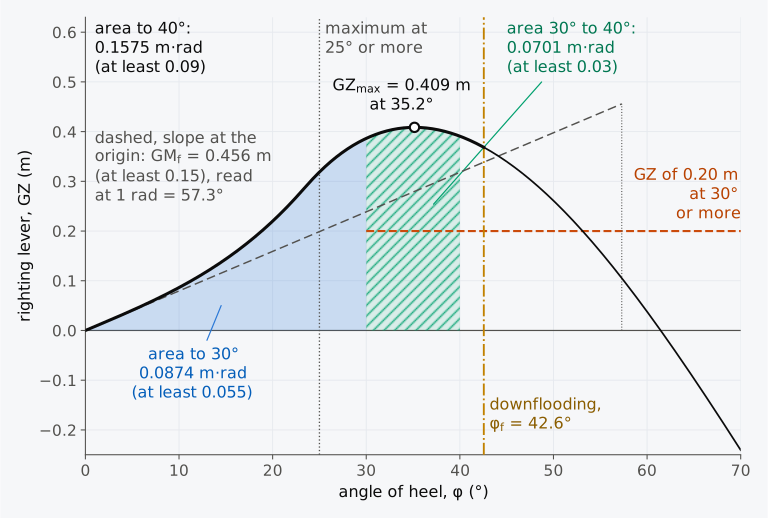
Figure 11.1 The general criteria of the IS Code, Part A, 2.2, on the curve of righting levers of the Series 60 ship in its fully loaded departure condition, corrected for free surfaces.
11.2.2 Checking a loading condition
Example 11.1. The departure condition and the general criteria. In its fully loaded departure condition the Series 60 ship displaces 7707 t, with KG = 5.887 m and free surface moments of 1573.5 t·m, the IS Code’s assumption for its consumable liquids. Its GM corrected for free surfaces is 0.456 m, and its downflooding angle 42.6°. Its levers corrected for free surfaces are:
φ (°) 0 5 10 15 20 25 30 35 40 45 50 55 60 GZ (m) 0 0.041 0.086 0.144 0.220 0.319 0.386 0.409 0.391 0.340 0.261 0.159 0.038 Check the criteria of Part A, 2.2.
11.2.3 Ships of wide beam and small depth
A ship of wide beam and small depth immerses the edge of its deck at a small angle, and its lever reaches its maximum soon after. For such ships, typically with a ratio of breadth to depth above 2.5, the criterion on the angle of the maximum may not be practicable5. Part A, 2.2.3, then allows alternative criteria of an equivalent level of safety, with the approval of the Administration. The Explanatory Notes to the IS Code, MSC.1/Circ.1281, suggest two: the maximum lever should lie at 15° or more, and the area under the curve up to the angle of the maximum, , should be at least
with in degrees. This is 0.070 m·rad when the maximum lies at 15°, and 0.055 m·rad, the area to 30°, when it lies at 30° or beyond5. The Code recommends criteria of this form for offshore supply vessels whose form makes Part A, 2.2, impracticable. For them it keeps the of 0.15 m, the area between 30° and 40° and the lever of 0.20 m at 30° or more5.
Example 11.2. A deck barge. A box-shaped deck barge 60 m long, 16 m wide and 6 m deep floats at a draught of 3.6 m in sea water. With its deck cargo, KG = 6.20 m, and it has no free surfaces and no openings that can flood. Its levers, computed with the trim free, are:
φ (°) 0 5 10 15 20 25 30 35 40 GZ (m) 0 0.135 0.281 0.450 0.602 0.613 0.495 0.269 −0.015 The largest lever is 0.622 m at 22.9°. Check the criteria of Part A, 2.2, and the alternative criteria of Eq. (11.3).
The curve of the barge bends where its deck edge is immersed (Fig. 11.2(a)). Its area is compared with the requirement of Eq. (11.3) in Fig. 11.2(b).
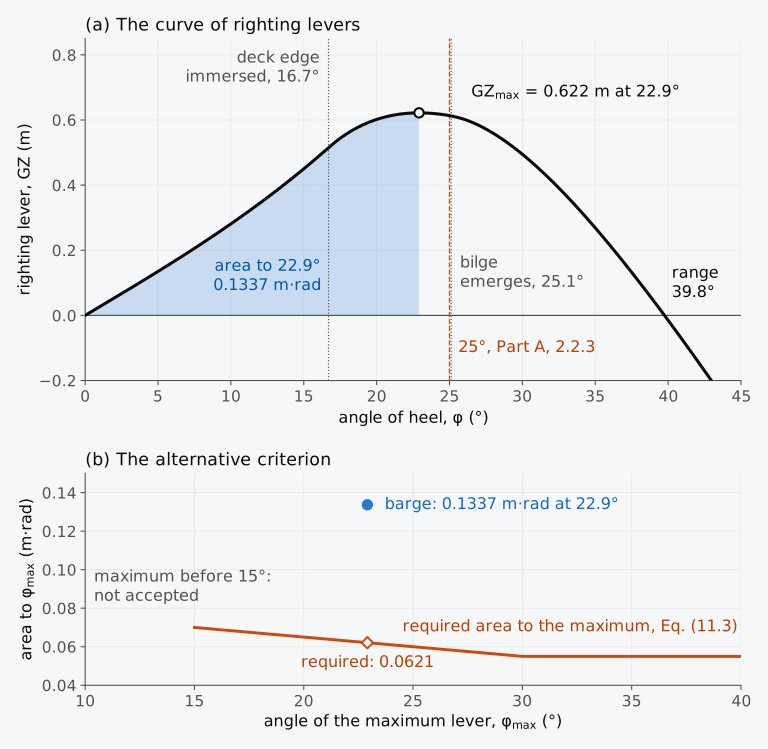
Figure 11.2 The deck barge of Example 11.2. (a) Its curve of righting levers. (b) The alternative criterion of Eq. (11.3) for ships of wide beam and small depth, with the area of the barge.
11.2.4 Criteria calculator (Calculator 11.1)
Calculator 11.1 checks a curve of righting levers against the criteria of Part A, 2.2, from levers entered every 5° from 0° to 60°, GM corrected for free surfaces and the downflooding angle. It joins the levers by parabolas through successive groups of three ordinates, which gives Simpson’s first rule for areas over whole pairs of intervals, as in Example 11.1. It finds the maximum lever from the parabola through the largest ordinate and its two neighbours, and reports each criterion with its margin. It can also apply the alternative criteria of Eq. (11.3), and Rahola’s criteria of 1939. The weather criterion is not part of it; Calculator 9.1 applies that criterion.
11.3 The loading conditions
11.3.1 The standard loading conditions
The criteria are checked in the loading conditions that the owner intends for the ship. If the owner gives no detailed conditions, the standard conditions of the IS Code are checked instead5. For a cargo ship there are four. The ship is fully loaded at departure, with the cargo spread homogeneously through all its cargo spaces and with full stores and fuel, and fully loaded on arrival, with 10 % of the stores and fuel left. The other two are the departure and arrival conditions in ballast, without cargo5. In the fully loaded departure condition the ship is assumed to be at its summer load line, with the water ballast tanks empty. If water ballast is needed in any condition, additional diagrams are calculated, and the quantity and position of the ballast are stated5.
The standard conditions are a minimum, and a ship intended to carry deck cargo is also checked fully loaded with it, at departure and on arrival5. The arrival condition of a timber carrier takes its deck cargo 10 % heavier from the water it absorbs5. The designer also checks hazards that come with the ship’s own work and that the standard conditions miss, such as an icebreaker riding up on the ice or a fishing vessel lifting its catch over the side3.
Historical note: the Load Line Rules of 1968
In the United Kingdom the stability information to be supplied to the master was set out first in a notice, M.375, and then in the Merchant Shipping (Load Line) Rules 1968, with some additions to the notice9. The Rules already asked for diagrams and statements of the ship light, in ballast at departure and on arrival, and loaded to its summer load line with a homogeneous cargo at departure and on arrival, with fuel, fresh water and stores reduced to 10 % of their capacity on arrival, as well as in its service conditions. GM and the curve of righting levers were to be corrected for free surfaces, and could be required from the trimmed waterline where the trim was significant. A fully loaded condition whose stability was judged unsatisfactory was marked as such, with a warning to the master9.
The fully loaded conditions of the Series 60 ship are those of Chapter 3. Its five holds are filled with a homogeneous cargo, and at departure it displaces 7707 t, its holds full before it reaches its summer load line at 7902 t. In the two ballast conditions the cargo is taken out, and two pairs of illustrative tanks in the double bottom, under holds 2 and 3, are pressed full of sea water, 130.0 t and 234.7 t. A third pair, under hold 5, holds 113.5 t; it is pressed full in a fifth condition, the fully loaded arrival condition with ballast under hold 5. The free surface moments are those of the IS Code’s assumption for consumable liquids, 1573.5 t·m in every condition, with the two small tanks, of diesel and lubricating oil, left out after the test of Sec. 5.3.4; with every tank counted they would be 1710.3 t·m (Example 5.4). Chapters 5, 8 and 9 use the actual contents of the tanks instead, 1021.2 t·m on departure and 1385.0 t·m on arrival. Their values of , 0.526 m on departure and 0.145 m on arrival on the trimmed hull, therefore differ from those of Table 11.3. The downflooding angle is that of an illustrative ventilator to the engine room, 2.0 m above the deck, 6.0 m from the centreline and 40.0 m forward of the AP, which cannot be closed weathertight. Flooding through it is taken to sink the ship, and each curve is cut at the downflooding angle5. The five conditions are listed in Table 11.3, and their spaces, tanks and waterlines are drawn in Fig. 11.3.
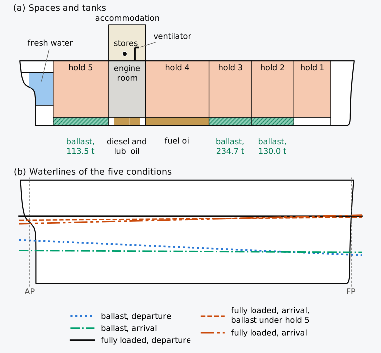
Figure 11.3 The Series 60 ship with the spaces and tanks of its loading conditions. (a) Heights drawn 2.5 times as large as lengths. (b) The waterlines of the conditions of Table 11.3, heights drawn four times as large as lengths.
Table 11.3 The standard loading conditions of the Series 60 ship, and the fully loaded arrival condition with ballast under hold 5. Trim positive by the stern; from free surface moments of 1573.5 t·m.
| Condition | (t) | KG (m) | (m) | (m) | Trim (m) | (m) | (°) |
|---|---|---|---|---|---|---|---|
| Fully loaded, departure | 7707.0 | 5.887 | 0.204 | 6.091 | 0.00 | 0.456 | 42.6 |
| Fully loaded, arrival | 7236.0 | 6.129 | 0.217 | 6.347 | −0.77 | 0.118 | 45.6 |
| Ballast, departure | 3771.7 | 5.594 | 0.417 | 6.011 | 1.34 | 1.245 | 63.0 |
| Ballast, arrival | 3300.7 | 6.084 | 0.477 | 6.561 | 0.16 | 1.036 | 67.8 |
| Fully loaded, arrival, ballast under hold 5 | 7349.5 | 6.045 | 0.214 | 6.259 | −0.27 | 0.237 | 44.6 |
11.3.2 The criteria in each condition
The general criteria and the weather criterion of Chapter 9 are evaluated for each condition in Table 11.4, from the levers of the whole hull at every degree. The curves are drawn in Fig. 11.4. The tables of the angle of roll in the weather criterion rest on data from ships with below 3.5, between −0.3 and 0.5 and roll periods below 20 s. Beyond these limits the tables still give their end values. For a ship outside them the IS Code allows the angle of roll to be found by model tests as an alternative, and the Administration may accept such determinations for any ship5. Table 11.5 shows which conditions lie within the limits. For those outside, Table 11.4 gives the steady heel and the ratio of areas computed with the end values, but no verdict on the weather criterion. That is a cautious choice made in these chapters, not a rule of the Code.
Table 11.4 The loading conditions of Table 11.3 against the general criteria and the weather criterion of the IS Code5. The last two columns are the angle of heel under the steady wind, , and the ratio of the areas of the weather criterion. In every condition 80 % of the angle at which the deck edge is immersed exceeds 16°, and 16° is the limit of .
| Condition | (m·rad) | (m·rad) | (m·rad) | GZ at 30° or more (m) | (°) | (m) | (°) | |
|---|---|---|---|---|---|---|---|---|
| Minimum | 0.055 | 0.09 | 0.03 | 0.20 | 25 | 0.15 | 16 at most | 1 |
| Fully loaded, departure | 0.0874 | 0.1575 | 0.0701 | 0.409 | 35.2 | 0.456 | 3.0 | 7.33 |
| Fully loaded, arrival | 0.0462, fails | 0.0966 | 0.0504 | 0.297 | 35.5 | 0.118, fails | 9.6 | 9.84 |
| Ballast, departure | 0.1787 | 0.3137 | 0.1349 | 0.939 | 47.5 | 1.245 | 3.5 | 4.55 |
| Ballast, arrival | 0.1356 | 0.2212 | 0.0856 | 0.543 | 47.2 | 1.036 | 5.1 | 2.83 |
| Fully loaded, arrival, ballast under hold 5 | 0.0609 | 0.1196 | 0.0586 | 0.344 | 35.5 | 0.237 | 6.0 | 9.50 |
Table 11.5 The loading conditions of Table 11.3 against the limits of the data on which the IS Code bases its tables of the angle of roll5.
| Condition | Limits of the data | Weather criterion |
|---|---|---|
| Fully loaded, departure | within | met |
| Fully loaded, arrival | roll period above 20 s | no verdict |
| Ballast, departure | above 3.5 and above 0.5 | no verdict |
| Ballast, arrival | above 3.5 and above 0.5 | no verdict |
| Fully loaded, arrival, ballast under hold 5 | roll period above 20 s | no verdict |
The fully loaded arrival condition fails two criteria: the area to 30°, 0.0462 against 0.055 m·rad, and , 0.118 against 0.15 m. In Sec. 5.3.4 this condition only just met the minimum , with 0.151 m under the Code’s assumption with the two small tanks left out, as here, and KM taken from the hydrostatic table on even keel. On arrival, however, the ship trims 0.77 m by the head. Its GM computed on the trimmed hull is 0.336 m instead of 0.368 m, and its falls below the minimum. Where the trim matters, the stability is calculated for the actual trim5.
The ballast conditions have large margins against the general criteria. Ballast arrival has the smallest ratio of the five, 2.83, because the ship floats high and offers the most windage for its displacement. Both ballast conditions lie outside the limits of Table 11.5.
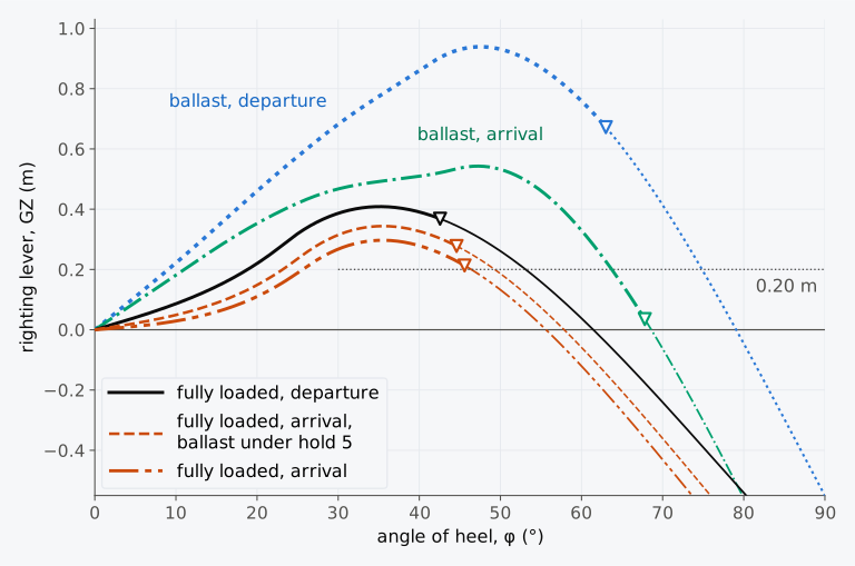
Figure 11.4 The curves of righting levers of the Series 60 ship in the loading conditions of Table 11.3, corrected for free surfaces.
11.3.3 Correcting a failing loading condition
A condition that fails is put right before the ship is loaded that way, for example with ballast low in the ship to lower G. The IS Code asks that the cargo allocated to a ship can be stowed to meet the criteria, if necessary by limiting its amount to the extent that ballast may be needed5. The ballast must be on board before the stability falls below the criteria, since a safe margin is required at every stage of the voyage5.
Example 11.3. Ballast for the arrival condition. On arrival the Series 60 ship displaces 7236.0 t with KG = 6.129 m, and fails the criteria on the area to 30° and on . The free surface moments are 1573.5 t·m. Before the fuel runs low, the pair of double-bottom tanks under hold 5 is pressed full of sea water: 113.5 t at 22.12 m forward of the AP and 0.66 m above the baseline. For the new waterline the hull gives KM = 6.496 m. Find the new displacement mass, KG and .
Where water ballast cannot put a condition right, because the lightship of a ship has grown in service or an alteration has raised G, the ship itself is changed. Removing weight from high in the ship is often an effective remedy, because it lowers G and the lighter draught usually lets B move further towards the low side as the ship heels. In a ship with little freeboard, added low weight may even reduce the levers at large angles4. The IS Code recommends that permanent ballast be placed to a plan approved by the Administration, secured against shifting and noted in the stability booklet, and that it be removed or moved only with the Administration’s approval5. Blisters fitted to the sides can widen the hull and improve its stability and draughts; the changed hull requires a new assessment4.
11.3.4 Changes during the voyage
The conditions of Table 11.3 are the ends of a voyage. Between them the ship burns fuel from tanks low in the hull, the free surfaces of slack tanks change, and the trim changes. A margin at both ends does not ensure one between them, because the stores, fuel and water are not used in a fixed order. The IS Code asks that a safe margin of stability be kept at all stages of the voyage, with regard to weight lost as fuel and stores are used and weight gained as water is absorbed or ice forms5. It asks that the number of slack tanks be kept to a minimum5, and it advises Administrations to take account of other influences, such as icing of topsides and water trapped on deck5.
For ships that operate where ice can form, the Code recommends that an allowance for icing be included in the loading conditions, and it lets Administrations apply stricter national standards5. For fishing vessels it recommends 30 kg/m² on exposed weather decks and gangways, and 7.5 kg/m² on the projected lateral area of each side above the waterline, with more for rails, booms and rigging5. For ships carrying timber deck cargoes it gives a formula for the ice on the cargo5.
11.4 Limiting curves of KG
11.4.1 The critical KG of each criterion
Every condition so far was checked by computing its curve of righting levers. The master needs a quicker test that works for any condition. Each criterion can be turned into the greatest height of G at which it is met, its critical KG, as a function of the displacement5. The cross curves of Chapter 8 give the lever KN about a point on the baseline, and for any height of G
where KG is corrected for free surfaces when GZ is to be the corrected lever. Integrated from 0 to φ, Eq. (11.4) gives
An area of at least is therefore reached when
and an area of at least 0.03 m·rad between 30° and , the lesser of 40° and , when
The lever reaches 0.20 m at some angle of 30° or more if KG does not exceed the largest value, over the angles from 30° to , of
The maximum of the curve lies at 25° or beyond if the slope of the curve at 25° is not negative, , that is when
with the slope per radian, provided that the curve has a single maximum. The criterion on GM is met for KG ≤ KM − 0.15 m.
The weather criterion has no closed form, because KG enters the angle of roll through the roll period and the factor of Chapter 9, and it is solved for KG by trial. The lowest of the critical values at a given displacement is the limiting KG, .
Three of these limits can be read as slopes when the cross curve is plotted against sin φ, a plot that the Explanatory Notes use to find critical values of KG graphically5. On such a plot the line KG sin φ is straight, with slope KG, and GZ is the height of the cross curve above it. The cross curve leaves the origin with the slope KM, and the criterion on GM admits lines no steeper than KM − 0.15 m. Since , the lever is greatest where the slope of the cross curve equals KG, and Eq. (11.9) is the slope of the cross curve at 25°. Equation (11.8) is the slope of the steepest line from the origin that still reaches the cross curve lowered by 0.20 m, at 30° or beyond, up to .
Example 11.4. The limiting KG of the general criteria at 7500 t. At a displacement mass of 7500 t on even keel, the Series 60 ship has KM = 6.523 m and a downflooding angle of 43.6°. The cross curves, computed with the trim free, give:
φ (°) 0 5 10 15 20 25 30 35 40 45 KN (m) 0 0.569 1.140 1.715 2.297 2.889 3.442 3.923 4.334 4.678 Find the critical KG of each general criterion of Part A, 2.2, and their limiting KG, . This example does not establish a limit for the weather criterion of Part A, 2.3.
In Animation 11.1, G rises in the fully loaded departure condition, with the cross curves of that condition. The area to 30° fails first, at = 6.332 m, then the area to 40° at 6.379 m and at 6.396 m. The lever of 0.20 m and the area between 30° and 40° follow at 6.469 m and 6.492 m. The condition itself has = 6.091 m, 0.241 m below the first limit.
Animation 11.1 The criteria of Part A, 2.2, as G rises in the fully loaded departure condition of the Series 60 ship, 7707 t. The curve of righting levers is drawn from Eq. (11.4) with the cross curves of the condition, for from 5.90 m to 6.60 m, and the area to 30° is shaded. As G rises, the curve sinks and its maximum moves to smaller angles. The area to 30° fails first, at 6.332 m, then the area to 40°, , the lever of 0.20 m and the area between 30° and 40°; the angle of the maximum is still met at 6.60 m. No sound; 11 s.
11.4.2 Minimum GM and maximum deadweight moment
SOLAS asks that the stability information include curves or tables of the minimum operational GM, or of the maximum allowable KG, against draught, together with the maximum permissible trim7. At a given draught and trim the two forms express a single limit, since
with KM for that draught and trim.
A third form avoids the division by the displacement. The deadweight moment of a condition is the moment of its deadweight about the baseline, with the free surface moments added, and its greatest permissible value at a displacement is
where and are the mass and the height of the centre of gravity of each item of the deadweight, and and those of the lightship. A condition meets the criteria if its deadweight moment does not exceed at its displacement. All three forms are in use, each plotted or tabulated against displacement or draught10.
Plotted against displacement, is the limiting curve of a deadweight-moment diagram, on which each condition is a point that must lie on or below the curve9. Loading a mass at a height above the baseline moves the point along a straight line of slope . The slope of the limiting curve is also a height, and from Eq. (11.11) it is
which lies below wherever falls with displacement. When the column of is interpolated linearly, the curve is straight between two tabulated displacements, and is the difference of their moments divided by the difference of the displacements. The margin then falls by for each tonne loaded, and while the displacement stays between those two entries the largest mass that can be loaded is
A mass loaded at the height leaves the margin unchanged, as a mass loaded at the neutral height of Chapter 5 leaves GM unchanged. A mass above it uses up the margin, and a mass below it adds to the margin. Where lies below , cargo stowed below the limiting KG can therefore still use up the margin. Each tonne of fuel used from tanks low in the ship lowers the deadweight moment by the small height of the tanks, but the limit by , and the margin shrinks. A tonne of stores used from high in the ship lowers the deadweight moment by more than the limit, and the margin grows. Put the other way, a consumable still on board above costs margin, and a consumable still on board below it adds margin. The state of the voyage with the least margin then depends on the order in which the consumables are used, and it can lie between the departure and the arrival.
11.4.3 The limiting curve of the Series 60 ship
Figure 11.5(a) develops an illustrative limiting curve for the Series 60 ship, from cross curves computed every 500 t for the ship on even keel when upright, with the trim free as the ship heels, and its limiting KG of the general criteria, , is listed in Table 11.6. From 4000 t to 8000 t the area to 30° governs. At 3500 t the lever of 0.20 m at 30° or more governs, with the areas to 30° and to 40° within 0.01 m. At 3000 t the area between 30° and 40° governs. The continued weather formula gives a lower critical KG there, 7.038 m, but the ship’s of 5.78 lies beyond the data of its tables, and Sec. 9.5.2 gives such a result no verdict. The formula is therefore drawn beside the limit and does not enter it. The criterion on the angle of the maximum governs nowhere, and its critical KG lies above KM over most of the range. The summer displacement mass, 7902 t, lies just below the end of the table. Above 8000 t the downflooding angle falls below 40°, and the area between 30° and the downflooding angle governs.
Table 11.6 Illustrative limiting KG of the general criteria, , on even keel and corrected for free surfaces, with the corresponding minimum and maximum deadweight moment, from Eqs. (11.10) and (11.11) with in place of . The lightship moment is 19522.5 t·m. is the lowest critical KG of the criteria of Part A, 2.2, alone; the continued weather formula does not enter it, so it is the limiting KG of all the criteria, , only where a valid assessment of the weather criterion establishes that it sets no lower limit.
| (t) | (m) | KM (m) | (m) | (m) | (t·m) | Governing criterion |
|---|---|---|---|---|---|---|
| 3000 | 2.812 | 7.914 | 7.199 | 0.715 | 2075 | area between 30° and 40° |
| 3500 | 3.213 | 7.405 | 7.018 | 0.387 | 5041 | lever of 0.20 m |
| 4000 | 3.608 | 7.037 | 6.762 | 0.275 | 7526 | area to 30° |
| 4500 | 3.997 | 6.786 | 6.571 | 0.215 | 10047 | area to 30° |
| 5000 | 4.381 | 6.620 | 6.438 | 0.182 | 12668 | area to 30° |
| 5500 | 4.761 | 6.516 | 6.353 | 0.163 | 15419 | area to 30° |
| 6000 | 5.135 | 6.463 | 6.306 | 0.157 | 18314 | area to 30° |
| 6500 | 5.504 | 6.454 | 6.290 | 0.164 | 21363 | area to 30° |
| 7000 | 5.866 | 6.478 | 6.299 | 0.179 | 24571 | area to 30° |
| 7500 | 6.222 | 6.523 | 6.321 | 0.202 | 27885 | area to 30° |
| 8000 | 6.571 | 6.581 | 6.349 | 0.232 | 31270 | area to 30° |
Between the rows of the table, the three forms are not interchangeable without care. KM changes with draught along a curve, and so does the product even where is taken as straight, and each column, interpolated linearly, gives a slightly different limit. At 3250 t, halfway between the first two rows, linear interpolation gives = 7.109 m, and = 3558 t·m, which corresponds to a KG of 7.102 m. The minimum , interpolated linearly to 0.551 m and subtracted from KM = 7.640 m at that draught, gives 7.089 m, about 0.02 m lower, because KM, which falls steeply there, curves below the straight line between the two rows. A table is therefore read in the column of the form being checked. For the limits of damage stability, SOLAS asks that curves of maximum KG correspond with a linear variation of GM between the draughts at which they are calculated7. IMO’s revised explanatory notes to the subdivision and stability regulations of SOLAS, Resolution MSC.429(98)/Rev.2, add that KM is then calculated at enough intermediate draughts for this11.
The loading conditions of Table 11.3 are plotted on Fig. 11.5(a). The fully loaded departure condition lies 0.242 m below the curve and the fully loaded arrival condition 0.037 m above it, or 0.056 m below with the ballast of Example 11.3; the ballast conditions lie far below.
The curve was computed on even keel, and the arrival condition trims 0.77 m by the head. At that trim the area to 30° is met only for up to 6.281 m, 0.029 m below the curve. The IS Code asks that limiting curves extend over the full range of operational trims, unless the Administration agrees that the effect of trim is not significant. Where no such curves are available, the master must verify that the condition does not differ from a condition already studied, or check the criteria by calculation for the actual trim5.
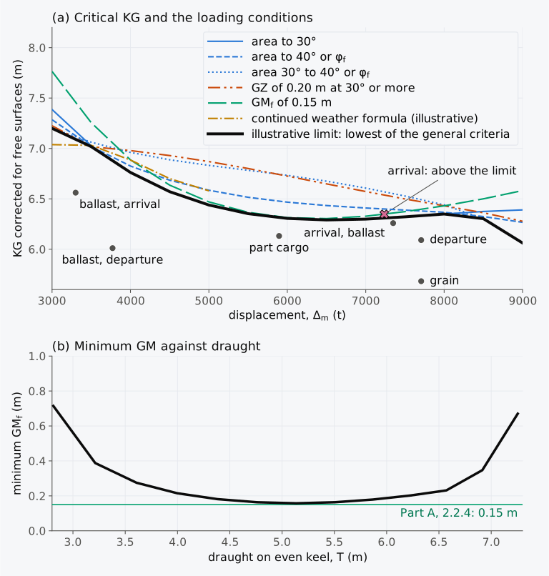
Figure 11.5 The illustrative limiting curve of the Series 60 ship on even keel. (a) The critical KG of each criterion of Part A, 2.2, and of the continued weather formula; the illustrative limit, the lowest of the general criteria (thick), which the weather formula does not enter; and the loading conditions of the chapter. The angle of the maximum governs nowhere and is not drawn. The continued weather formula is drawn from 3000 t to 5000 t, where it gives a critical KG below KM; from 5500 t to 8500 t, at roll periods far beyond the data of its tables, it gives none within the sampled range, and its single value at 9000 t is not drawn. (b) The illustrative limit as a minimum against draught.
Example 11.5. A part cargo. The Series 60 ship sails with a part cargo in holds 3 and 4 only: 960.0 t at 5.53 m and 1528.0 t at 5.50 m above the baseline. The lightship, 2850.0 t at 6.85 m, and the stores, fuel and water of the departure condition give together 3407.0 t with a moment of 20860.4 t·m about the baseline. On the voyage the ship uses 471.0 t of the stores, fuel and water, with a moment of 1014.7 t·m, in an order that is not fixed. The part used of each, and the height of its centre of gravity above the baseline, are:
Part used Mass (t) Height (m) Stores 13.0 10.800 Fuel oil, port 171.0 0.681 Fuel oil, starboard 157.0 0.627 Diesel oil 31.0 0.490 Fresh water 99.0 6.507 The two fuel oil tanks, one on each side of the centreline, are used together, so as not to list the ship. The free surface moments are 1573.5 t·m throughout. Using Table 11.6, with each limit interpolated linearly in its own column, (a) check the departure condition against the limiting KG of the general criteria, and (b) check the departure and arrival conditions with deadweight moments. (c) The double-bottom tanks under holds 3 and 5 are pressed full of sea water before sailing, 234.7 t at 0.64 m and 113.5 t at 0.66 m above the baseline. Find how much deck cargo, with its centre of gravity 11.50 m above the baseline, the ship can then carry with a margin at every stage of the voyage, using the illustrative limits of Table 11.6, which do not include the weather criterion.
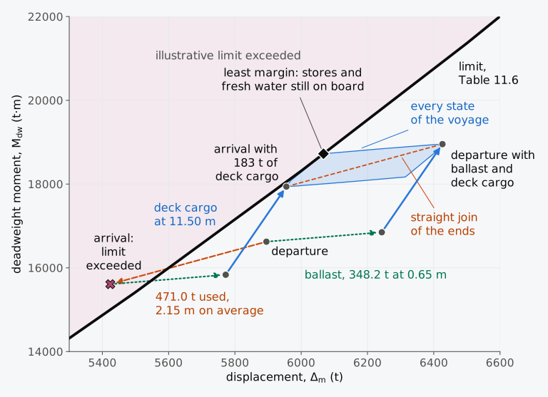
Figure 11.6 The part cargo of Example 11.5 on the deadweight-moment diagram of the Series 60 ship, with 183 t of deck cargo. The limit is that of Table 11.6, straight between the tabulated displacements; the band holds every state of the voyage.
11.4.4 Exploring the limiting curve (Explorer 11.1)
In Explorer 11.1 you can choose a displacement mass of the Series 60 ship between 3000 t and 8000 t and a height of G corrected for free surfaces, and see the curve of righting levers of Eq. (11.4) with each criterion of Part A, 2.2, marked as met or not met. A second graph plots the critical KG of every criterion against displacement, with your point. The cross curves come from the hull, every 500 t on even keel, and are interpolated linearly between displacements. The critical KG of the continued weather formula, computed in advance where one was found, is shown beside the illustrative limit, which is the lowest of the general criteria. The explorer checks the six general criteria and gives no verdict on the weather criterion.
11.5 Stability information on board
11.5.1 The stability booklet
The limiting curves reach the master as part of the stability information of the ship. SOLAS requires that the master be supplied with the information needed to obtain, by rapid and simple processes, accurate guidance on the stability of the ship under varying conditions of service. A copy goes to the Administration7. The information should include curves or tables of the minimum operational GM, or of the maximum allowable KG, and of the maximum permissible trim, against draught, which ensure compliance with the intact and, where they apply, the damage stability requirements7. These data are presented as consolidated data for intact and damage stability and cover the full operating range of draught and trim7. The Load Line Convention asks that the stability information be in a form approved by the Administration or a recognized organization, and that it be carried on board at all times with evidence of its approval8. When an alteration of the ship materially affects the stability information, amended information must be provided, and the ship re-inclined if necessary7,8. The limits on the change of the lightship beyond which the information is amended, or the ship inclined again, are set out in Sec. 10.8. The extended deckhouse of the Kuru was such an alteration.
The IS Code requires each ship to which these provisions apply to carry a stability booklet, approved by the Administration, with enough information for the master to operate the ship in compliance with the Code5. Its format varies with the type of ship and its operation. Among the contents that the Code recommends are a general description of the ship and instructions on the use of the booklet, and general arrangement plans that show the watertight compartments, closures, vents and downflooding angles. Others are hydrostatic curves or tables and cross curves of stability on a free-trimming basis, capacity and tank sounding tables with free surface data, and curves or tables of maximum KG or minimum GM. The booklet also gives standard operating conditions with examples for developing others, a brief description of the calculations and their assumptions, and the report of the inclining test5. At its discretion, the Administration may accept a simplified booklet in an approved form5.
11.5.2 Stability instruments
A stability instrument, a computer and its approved software, may supplement the booklet, and it must then be approved by the Administration5. It is not a substitute for the booklet; its results apply only to the ship for which it was approved, and its approval lapses when a change of the ship alters the booklet5. A passive system takes the contents of the tanks as entered by hand, and an active system reads some of them from sensors5. For each loading condition the software lists every criterion with its limit, the value obtained and whether it is met5, in the form of Table 11.4.
Part B of the IS Code asks that the software be tested on at least four conditions taken from the approved booklet, among them a departure and an arrival condition and, in a ship that carries grain, a condition with a partly filled grain compartment5. Under the Guidelines for the approval of stability instruments, MSC.1/Circ.1229, a program that computes from a model of the hull should reproduce the levers within 5 % / 5 cm max, as the Circular writes the tolerance, and the downflooding angle within 2° of the approved values12. The unified requirement of the International Association of Classification Societies, IACS UR L5, Rev. 4, gives the same values without “max”, and allows the greater of the two values of a tolerance that has two13. Section 2.10.2 treats both. The Code also asks the master to have a test condition run after installation, and again at each annual survey, and its results compared with the approved values5.
11.5.3 The master’s part
Meeting the criteria does not make a ship immune to capsizing, whatever the circumstances, and it does not relieve the master of responsibility. The IS Code therefore asks masters to use prudence and good seamanship, with regard to the season, the weather forecasts and the area of navigation, and to choose speed and course accordingly5. Before the voyage, cargo, cranes and large items of equipment should be stowed or lashed so that they cannot shift at sea5.
The stability information relies on its stated assumptions about the buoyancy of enclosed spaces and the weathertight closure of hatches, doors, ventilators and air pipes on exposed decks10. The Code asks that such openings be closed in adverse weather and kept closed at sea except when needed for working the ship5, and that the booklet of a roll-on roll-off passenger ship stress how quickly such a ship can capsize once water enters its vehicle deck5.
In following, quartering or head seas the dangers of Sec. 11.1.2, singly or together, can threaten capsize, and the master alters speed or course to avoid them5. Guidance for this is given in the Revised guidance to the master for avoiding dangerous situations in adverse weather and sea conditions (MSC.1/Circ.1228)14.
11.6 Grain in bulk
11.6.1 The assumed shift of the grain
A cargo of grain in bulk, one of the cases of Table 11.1, has criteria and stability information of its own. When a ship rolls, the surface of the grain in a hold can slide towards the low side, and the voids that form under the deck as the grain settles let it move even in a full hold. The International Code for the Safe Carriage of Grain in Bulk, the International Grain Code, adopted by Resolution MSC.23(59), is mandatory for cargo ships carrying grain, which must hold a document of authorization issued under it7. Part A, 3.4, of the IS Code refers such ships to it5.
The Grain Code assumes how the grain moves. In a filled compartment that has been trimmed, a void is taken under every boundary less steep than 30°, such as the deck, with an average depth that depends on the depth of the girders and on the distance from the hatchway. After the shift, the grain surface in the voids lies at 15° to the horizontal15. In a partly filled compartment whose surface is not secured, the shifted surface lies at 25° to the horizontal15. The Code prescribes these angles and does not derive them from the roll of the ship and the angle of repose of the grain, as the angle-of-repose model of Chapter 5 does for a bulk cargo. The assumed shift is transverse: the Code follows the grain surface in transverse sections of each compartment and multiplies the moment of a section by the length of the portion of the compartment that it represents15, and the shift heels the ship without trimming it. The shift is measured by its volumetric heeling moment, , the volume of grain moved times the distance its centroid moves across the ship, in m⁴. For a partly filled compartment the moment is multiplied by 1.12, to allow for the rise of the centre of gravity of the grain as its surface tilts. In a filled compartment the centre of gravity of the grain is normally taken at the centroid of the whole space; only where the Administration lets the voids be counted in its height does a factor of 1.06 multiply the moment15.
In a partly filled compartment of length and breadth , with vertical sides where the surface moves, a surface tilted by an angle α moves a wedge of grain across the space. Equation (5.11), divided by the density of the cargo, gives its volumetric heeling moment as the second moment of area of the free surface times tan α,
provided that the tilted surface stays clear of the top and bottom of the space. A longitudinal division on the centreline halves the breadth of each free surface, and falls to a quarter. The Grain Code asks for such a division to extend above the grain surface, and below it, by one eighth of the greatest breadth of the compartment15. With α = 25° the surface in each half rises (/4) tan 25° = 0.117 , which stays within the division. Other means reduce the shift or prevent it: the grain may be overstowed with other cargo, bundled, strapped or lashed, or secured with wire mesh, and a hold may be built with sloping longitudinal bulkheads so that it trims itself4.
11.6.2 The heeling arm and the criteria
The Grain Code turns the volumetric heeling moment of all the holds into a heeling arm,
at 0° and at 40° of heel15. Here SF is the stowage factor of the grain as attested by the loading facility, in m³/t15, and the displacement mass in tonnes. The heeling arm is the straight line through the two values,
which is how the Grain Code draws it10,15. The Code’s figure presents the line as an approximation to the curve of heeling arms due to the transverse shift15. A shift that moves G across the ship by GG′ and raises it by δKG reduces the lever at an angle φ by GG′ cos φ + δKG sin φ, as in Chapter 8. The factor 1.12 of a partly filled compartment stands in for the second term. Among its cross curves, the grain loading information must include those for 12° and 40° of heel15.
The intact stability of a ship carrying grain must meet three criteria throughout the voyage. The angle of heel due to the shift of grain may not exceed 12°, nor, for ships built on or after 1 January 1994, the angle at which the deck edge is immersed, if that is less. The residual area between the curve of righting levers and the heeling arm, up to the angle of the largest difference between them, 40° or the downflooding angle, whichever is least, must be at least 0.075 m·rad. GM must be at least 0.30 m when corrected for the free surfaces of liquids in tanks15. These criteria are older than the Grain Code: Chapter VI of SOLAS, as adopted in 1974, already set all three, without the limit of the deck edge16.
If the government of the port of loading so requires, the master must show before loading that the ship will meet the criteria at all stages of the voyage, and after loading must make sure that the ship is upright before it sails15. The grain loading information of an authorized ship gives the volumetric heeling moments of each compartment, and for ships built since the Grain Code came into force also tables of the maximum permissible heeling moment, with which the master checks the criteria without drawing the curves15.
Example 11.6. Grain in the Series 60 ship. The Series 60 ship loads a parcel of 3996.2 t of grain stowing at 1.80 m³/t, and hold 1 is left empty. Holds 2, 3 and 5 are filled and trimmed. The rest of the grain, 978.1 t, lies in hold 4, 24.0 m long, whose sides are vertical over the full breadth of the ship, 16.256 m, at the level of the grain; it is partly filled to a level surface 5.76 m above the baseline, and its surface is not secured. The fore peak tank and the double-bottom tanks under holds 2 and 5 are pressed full of water ballast, 303.8 t in all. The grain loading information gives the volumetric heeling moments of holds 2, 3 and 5 as 220, 330 and 340 m⁴. At departure the ship displaces 7707 t and trims 0.73 m by the stern, with KG = 5.479 m and = 0.894 m; the deck edge is immersed at 23.3° and the downflooding angle is 41.9°. On the voyage the ship uses 471.0 t of stores, fuel and water, with a moment of 1014.7 t·m about the baseline. On arrival it trims 0.02 m by the stern, = 0.586 m, the deck edge is immersed at 25.2° and the downflooding angle is 44.9°. The levers at these trims, corrected for free surfaces, are:
φ (°) 0 5 10 15 20 25 30 35 40 45 50 GZ, departure (m) 0 0.079 0.163 0.257 0.370 0.503 0.600 0.651 0.661 0.634 0.578 GZ, arrival (m) 0 0.052 0.110 0.179 0.268 0.383 0.497 0.557 0.568 0.537 0.471 Check the criteria of the Grain Code at departure (a) with hold 4 open from side to side, and (b) with a centreline division in hold 4. Check them on arrival (c) with the division, and (d) with the surface in hold 4 secured by strapping or lashing instead.
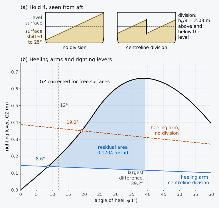
Figure 11.7 Grain in the Series 60 ship, Example 11.6. (a) The assumed shift of the grain surface in hold 4, without and with a centreline division drawn at the least extent that the Grain Code requires; a division reaching the tank top would also comply. (b) The heeling arms at departure, with the curve of righting levers.
The tables of the maximum permissible heeling moment are built from the criteria. At a given displacement and , the largest arm that still meets the criteria on the heel and on the residual area, multiplied by the displacement mass, gives the maximum permissible heeling moment, a moment of mass in t·m; is checked on its own. A loading is acceptable if /SF does not exceed the permissible moment10.
In the grain condition of Example 11.6 the heel governs. Interpolated linearly, its levers give 0.163 + 0.4 × (0.257 − 0.163) = 0.2006 m at 12°. The arm at 12° is 0.94 , and may reach 0.2006/0.94 = 0.2134 m; at that arm the residual area is still about 0.14 m·rad. The permissible moment is 0.2134 × 7707 = 1645 t·m. With the division, /SF = 2012/1.80 = 1118 t·m, within it, and without the division 5377/1.80 = 2987 t·m, far beyond it. On arrival the heel still governs. The arrival levers give 0.110 + 0.4 × (0.179 − 0.110) = 0.1376 m at 12°, may reach 0.1376/0.94 = 0.1464 m, and the permissible moment falls to 0.1464 × 7236.0 = 1059 t·m. The 1118 t·m of the division exceeds it, and with hold 4 secured, /SF = 890/1.80 = 494 t·m lies within it. Between 10° and 15° both curves of levers bend upwards, and linear interpolation overstates the lever at 12° and the permissible moment with it. From the levers at every degree the permissible moments are 1631 t·m at departure and 1044 t·m on arrival, and no verdict changes.
11.7 The Kuru and Rahola’s criteria
Jaakko Rahola began from the accidents: in his doctoral thesis of 1939 he examined 34 accidents abroad, and studied in detail 13 ships for which reliable curves of righting levers were available, most of them small coastal vessels. He classed their loading conditions as adequate, critical or insufficient, and drew a line between sufficient and critical stability through the levers of each class2. The result was a minimum rule for the curve of a seagoing ship: its lever should be at least 0.14 m at 20° and 0.20 m at 30°, and its maximum should lie at 35° or more2. The area under the curve up to an angle should be at least 0.080 m·rad, where is the least of 40°, the angle of the maximum, the downflooding angle and the angle at which unsecured cargo would shift2. For the vessels of the Finnish lakes he studied the heeling moments of a turn, of the wind and of passengers crowding to one side, and took the most unfavourable situation, a turn in a wind, to set the minimum stability. In the last chapter of the thesis his criteria were applied to the S2 and the Kuru2. The criteria rested on personal judgement and on a limited set of data2.
Rahola’s criteria spread to other countries after the Second World War, and in 1968 their simplicity made them the basis of the first international provision on intact stability, adopted by IMCO17. The 1960 SOLAS Conference had not agreed on intact stability and had passed the question to IMCO for urgent study17. Resolution A.167(ES.IV), for passenger and cargo ships under 100 m long4, modified Rahola’s method with the statistics of casualties and safe ships that Sec. 11.1.1 describes17. It asked that the maximum lever lie at an angle preferably above 30° but not below 25°, and the second part of that wording later became the present criterion17. National rules could ask for more; the Load Line Rules of the United Kingdom of 1968 required the maximum at 30° or more9. When the criteria were taken into the Code on Intact Stability, Resolution A.749(18), the limit of 100 m was removed4. The IS Code of 2008 made them mandatory17.
Both sets of criteria are applied in Table 11.7 to three conditions of the Series 60 ship, and Calculator 11.1 can apply Rahola’s criteria to any curve.
Table 11.7 Rahola’s criteria2 and the general criteria of the IS Code5 for three loading conditions of the Series 60 ship, from the levers corrected for free surfaces. For Rahola’s area, is the angle of the maximum in all three conditions.
| Criterion | Minimum | Fully loaded, departure | Fully loaded, arrival | Arrival, ballast under hold 5 |
|---|---|---|---|---|
| Rahola | ||||
| GZ at 20° (m) | 0.14 | 0.220 | 0.110, fails | 0.148 |
| GZ at 30° (m) | 0.20 | 0.386 | 0.267 | 0.315 |
| Angle of the maximum (°) | 35 | 35.2 | 35.5 | 35.5 |
| Area to (m·rad) | 0.080 | 0.1235 | 0.0736, fails | 0.0932 |
| IS Code, Part A, 2.2 | ||||
| Area to 30° (m·rad) | 0.055 | 0.0874 | 0.0462, fails | 0.0609 |
| (m) | 0.15 | 0.456 | 0.118, fails | 0.237 |
| Other four criteria | met | met | met | |
The two sets agree on these conditions, whose maxima lie just beyond 35°, the angle that Rahola asked for, ten degrees later than the IS Code. A ship whose curve peaks between 25° and 35° could meet the IS Code and fail Rahola’s rule.
11.8 The second generation intact stability criteria
11.8.1 Failure modes and levels of assessment
Every criterion of this chapter judges the curve of righting levers of the ship in still water, as the working group of the 1960s chose. Section 9.5.5 showed how the lever changes as a wave passes along the hull, and how the change can lead to a pure loss of stability or to parametric roll. In December 2020 IMO issued the Interim guidelines on the second generation intact stability criteria, MSC.1/Circ.1627, and invited Member States to use them as complementary measures when applying the mandatory criteria of Part A18; the guidelines are not meant to replace those criteria18. They assess five modes of stability failure in waves: the dead ship condition, excessive acceleration, pure loss of stability, parametric roll, and surf-riding with broaching18. The criteria of Part A rest mainly on records of casualties, and the new criteria mainly on first principles18.
Each mode is assessed in steps. Level 1 is an initial check from simple data, and a loading condition that passes it is classified as not vulnerable under that level of the guidelines. A condition that fails goes on to Level 2, a more detailed calculation. If it fails again, the ship is given a direct stability assessment, in which its motions in irregular waves are simulated, or operational limitations, or the design is revised or the loading condition given up18. The routes carry equal regulatory weight, and any of them may be used on its own18. The guidelines are issued for trial use, because the criteria are not equally robust for every mode; those for parametric roll and surf-riding were judged to have a sufficient scientific basis for regulatory use18.
Operational measures take two forms. Operational limitations confine the ship, in a given loading condition, to an area or route and season, or to sea states up to a stated significant wave height. Operational guidance tells the master which combinations of speed and heading relative to the waves to avoid in each sea state18. It is presented graphically, for example as a polar diagram of speed and heading relative to the waves18, and it may be prepared by simplified, conservative approaches built on the Level 1 and Level 2 criteria18. A loading condition is not acceptable if the situations to be avoided take more than 0.2 of the total operational time18. Operational measures prepared in this way may replace the guidance to the master of MSC.1/Circ.1228 for the modes they cover18.
11.8.2 Parametric roll at the first level
The Level 1 check for parametric roll needs only hydrostatic data: the transverse second moment of the waterplane, , at two level waterlines above and below the waterline of the loading condition. The amplitude of the variation of GM in waves is estimated as
at the draughts
where is the mean draught of the condition, measured amidships, that of the fully loaded departure condition, the depth and = 0.0167. The waterplanes may be taken on even keel even for a ship that trims18. The constant is a wave steepness, the ratio of the height of a wave to its length, and is then half the height of a wave as long as the ship, with and the draughts at its crest and its trough19. The length is that of the IS Code, the larger of 96 % of the length of the waterline at 85 % of the least moulded depth and the distance from the fore side of the stem to the axis of the rudder stock on that waterline5. The condition is classified as not vulnerable to parametric roll at Level 1 if both
hold, where is the volume of displacement up to the depth on even keel and the waterplane area at the draught , with GM corrected for free surfaces18. The second condition holds with equality where the sides are vertical from the waterline to the deck, and with a margin where they flare outwards. The limit is 1.87 for a ship with sharp bilges. For a round-bilged ship it rises with the total area of the bilge keels, ; where the midship section coefficient of the fully loaded ship exceeds 0.96, , with taken as at most 4 in this formula18. Bilge keels damp the roll, and large roll damping makes parametric roll less likely4. The estimate of is conservative, and a condition that fails the check is not shown to be unsafe, only to need a closer assessment18.
Example 11.7. Parametric roll at the first level. The Series 60 ship has = 122.37 m by the definition of the IS Code, = 16.256 m and = 9.75 m, and a volume of displacement up to the depth on even keel of 12608 m³. Its bilge keels have a total area of 28.8 m², and the midship section coefficient of the fully loaded departure condition is 0.974. On even keel the transverse second moment of the waterplane is 21690, 22010, 24663 and 25032 m⁴ at draughts of 5.102, 5.345, 7.146 and 7.389 m, and the waterplane area is 1378.1 m² at 6.124 m and 1394.7 m² at 6.367 m. Check the Level 1 criterion for parametric roll in (a) the fully loaded departure condition, 7707 t at a mean draught of 6.367 m with = 0.456 m, and (b) the fully loaded arrival condition with ballast under hold 5, 7349.5 t at a mean draught of 6.124 m with = 0.237 m.
11.9 Checking a change of loading
With the criteria of this chapter, the calculation that began with the weight table of Chapter 3 can be carried to its end for any change of loading of the Series 60 ship. Shortly before it sails, a crate of machinery is offered for its deck, and the master must decide whether the ship can carry the crate to its port of arrival.
Example 11.8. A crate on deck. The Series 60 ship is ready to sail in its fully loaded departure condition, 7707 t with = 59.21 m and KG = 5.887 m, when it is asked to carry a crate of machinery of 60.0 t. Stowed on the hatch cover of hold 2, the crate has its centre of gravity on the centreline, 92.0 m forward of the AP and 11.50 m above the baseline. It is 12.0 m long and 2.5 m high, which adds 30.0 m² of lateral area at the height of its centre of gravity. The double-bottom tanks under hold 5 are pressed full before it sails, 113.5 t at 22.12 m forward of the AP and 0.66 m above the baseline. On the voyage it uses 471.0 t of stores, fuel and water, with moments of 20551.8 t·m about the AP and 1014.7 t·m about the baseline, in an order that is not fixed. Of this, 13.0 t are stores, 36.0 m forward of the AP and 10.80 m above the baseline; the fuel and diesel oil come from the double bottom, the fuel from two wing tanks used together, and the fresh water from the aft peak. The fuel in the wing tanks has a moment about the centreline of 56.85 t·m to port at departure and 3.12 t·m on arrival. The free surface moments are 1573.5 t·m throughout, the IS Code’s assumption for its consumable liquids, and its summer displacement mass is 7902 t. At draughts of 6.0 m and 6.2 m, Table 6.1 gives displacement masses of 7187.7 t and 7469.9 t, = 59.39 m and 59.29 m, = 57.02 m and 56.68 m, and MCT 1 cm = 82.75 and 85.07 t·m/cm. On arrival with the crate over hold 2, the deck edge is immersed at 24.3° and the downflooding angle is 44.5°. The hull, solved with the trim free, then gives KM = 6.492 m and the first row of levers KN below. With the crate stowed over hold 4 instead, 56.0 m forward of the AP and 11.50 m above the baseline, the hull gives KM = 6.503 m and the second row.
φ (°) 0 5 10 15 20 25 30 35 40 45 50 KN, hold 2 (m) 0 0.567 1.135 1.708 2.288 2.879 3.438 3.924 4.339 4.686 4.970 KN, hold 4 (m) 0 0.568 1.137 1.710 2.291 2.882 3.442 3.928 4.342 4.689 4.972 (a) With the crate over hold 2, find the arrival draughts, check Part A, 2.2, and calculate the weather quantities while checking their applicability. (b) Check the criteria on arrival with the crate over hold 4. (c) Check both stowages between departure and arrival, and decide how the crate can be carried.
In Example 11.8 the free surfaces took about a third of the area to 30° (Fig. 11.8(a)). The difference between the two stowages came from their trim (Fig. 11.8(b)).
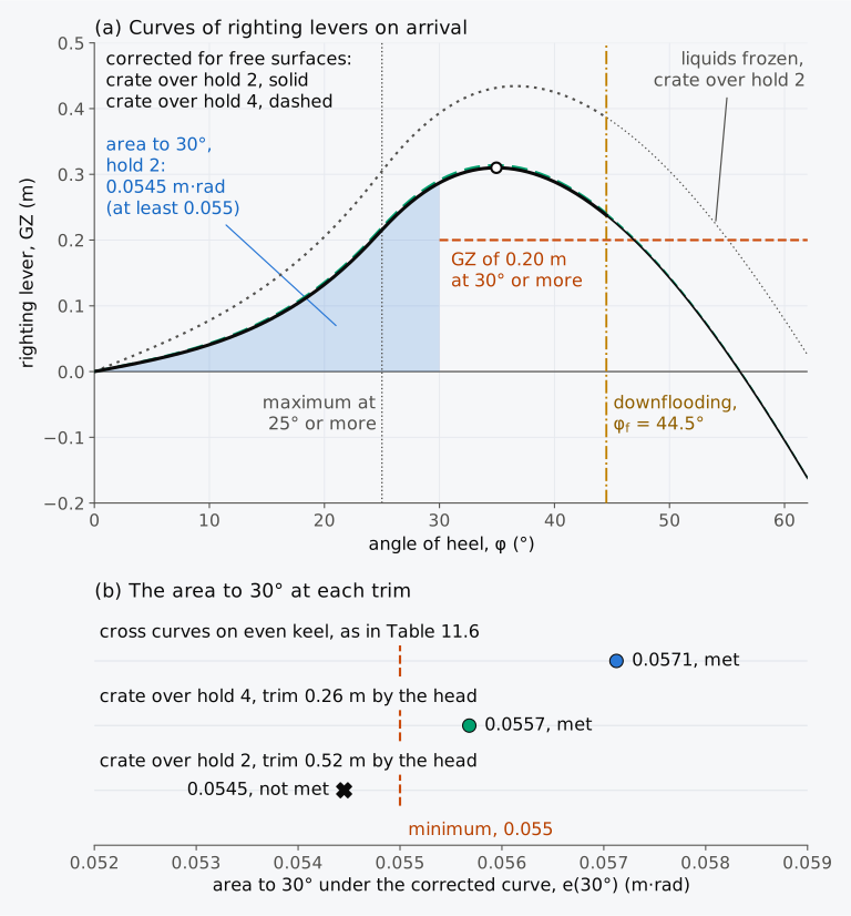
Figure 11.8 The Series 60 ship on arrival with the crate of Example 11.8. (a) Curves of righting levers for the two stowages, corrected for free surfaces, and the curve with the liquids frozen. (b) The area to 30° for each stowage at its own trim, and on even keel as in Table 11.6.
The example does not establish that the ship is safe with the crate on board. Only one loading condition and the states of its voyage were checked, with the free surface moments held at the IS Code’s assumption, in still water and with the hull intact. The other conditions of its stability booklet were not considered, nor its stability after damage, nor the securing of the crate and the strength of the hatch cover that carries it. The weather criterion was given no verdict, and the first-level check of parametric roll only screens for vulnerability in that mode. On board, such a decision rests on stability information approved by the Administration5. The loading of the Series 60 ship, its tanks and its openings are illustrative.
11.10 Stability criteria and stability information in industry today
This section describes practice in 2026.
Grain. On 1 January 2026 amendments to the International Grain Code, adopted by Resolution MSC.552(108) on 23 May 2024, entered into force20,21. They add a loading condition for a specially suitable compartment, filled at least to the lower edge of the hatch end beams, with the grain in its ends left at its natural angle of repose21. For such a compartment filled as fully as possible in way of its hatchway, the Code of 1991 already assumed a surface sloping at 30° from the lower edge of the hatch end beam, and a shift to 15° abreast the hatchway and 25° in the ends15. In the new condition the shifted surface lies at 25° in the hatchway as well as in the ends, and the heeling moment is multiplied by 1.12, as for a partly filled compartment21. The grain loading manual must then give heeling moments for the new condition20.
Operational guidance. In a draft information paper for the session of IMO’s Sub-Committee on Ship Design and Construction in January 2026, Finland reported a method of Aalto University and NAPA that computes simplified operational guidance against parametric roll for any speed and heading relative to the waves, validated mainly for large container ships22.
Methods in software. An article in the knowledge base of Bentley Systems for its offshore software describes a limiting KG analysis. The analysis computes the curve of righting levers at a trial height of G, checks the selected criteria and iterates to the greatest height at which all of them pass, to within about 1 mm. The article notes that the iteration assumes the criteria to be more easily met as G is lowered, which is not always so, for example when the angle of the maximum hardly changes with KG or when the downflooding angle moves the other way23. The closed forms of Sec. 11.4.1 avoid the iteration for the criteria of Part A, 2.2, but not for the weather criterion.
Data. The sources consulted for this section describe no common format for exchanging the contents of a stability booklet between programs. The Load Line Convention asks only that the information be in a form approved by the Administration or a recognized organization8.
11.11 From intact stability to damage stability
Every curve of this chapter assumed a watertight hull, and the criteria guard an intact ship against capsizing in wind and waves and against the shift of its cargo. A collision or a grounding can open a compartment to the sea; the ship then sinks deeper, trims and heels, and the water that enters may have a free surface of its own. SOLAS sets requirements for the survival of ships after damage, and the limiting curves of GM in the stability information combine them with the intact criteria7. In Chapter 12 we will see how the floating position and the stability of a damaged ship are calculated, by the methods of lost buoyancy and added weight, and the criteria that a damaged ship must meet.
Summary
- Stability criteria set the least stability with which a ship may be operated; they do not make it immune to capsizing. Within the applicable conventions, the general criteria of the IS Code, mandatory under its Part A for cargo and passenger ships of 24 m and over, judge the curve of righting levers in still water and came from statistics of casualties and of ships operated safely.
- Part A, 2.2, sets six minimums on the curve corrected for free surfaces, Table 11.2: areas of 0.055 m·rad to 30°, 0.09 m·rad to 40° or and 0.03 m·rad between them, Eq. (11.1); a lever of 0.20 m at 30° or more; the maximum at 25° or more; and of 0.15 m. They judge the dynamic, statical and initial stability. For ships of wide beam and small depth, the Administration may accept a maximum between 15° and 30° if the area up to it meets Eq. (11.3).
- The criteria are checked in the loading conditions intended by the owner, or in the standard conditions of the Code, at the actual trim and at every stage of the voyage. A failing condition is put right with ballast low in the ship or, where ballast cannot, by changing the ship.
- With GZ = KN − KG sin φ, Eq. (11.4), each criterion gives a critical KG, Eqs. (11.6) to (11.9). The lowest of them at a given displacement is the limiting KG, also given as a minimum GM, Eq. (11.10), or as a maximum deadweight moment, Eq. (11.11). The limiting curve of the Series 60 ship is illustrative and rests on the general criteria; the continued weather formula, lower at 3000 t but beyond the data of its tables there, is drawn beside it. On the deadweight-moment diagram a mass loaded at a height moves a condition along a line of slope . A consumable still on board above the slope of the limit costs margin, and a consumable below it adds margin. The least margin of a voyage depends on the order in which the stores, fuel and water are used, and it can lie between the ends of the voyage. Floated on the hull, each state is checked at its own trim and, where G lies off the centreline, for a heel towards the low side.
- SOLAS, the Load Line Convention and the IS Code require approved stability information on board, with limiting curves of GM or KG against draught, amended after alterations of the lightship. A stability instrument supplements the booklet and is tested on approved conditions. The stability shown assumes that exposed openings are closed weathertight.
- The International Grain Code assumes the grain surface to shift to 15° in the voids of filled compartments and to 25° in partly filled compartments whose surface is not secured, Eq. (11.12), and turns the shift into a heeling arm, Eq. (11.13). Throughout the voyage the heel must not exceed 12°, and in ships built since 1994 it must not exceed the angle at which the deck edge is immersed. The residual area must be at least 0.075 m·rad and at least 0.30 m. A centreline division cuts the moment of a partly filled hold with vertical sides to a quarter, and securing its surface reduces or prevents the shift.
- Rahola’s criteria of 1939, prompted by the losses of the Kuru and the S2, became the basis of the international criteria adopted in 1968 and made mandatory by the IS Code of 2008.
- The second generation criteria of MSC.1/Circ.1627, for trial use beside Part A, assess five modes of stability failure in waves, from a simple check to direct assessment and operational measures. The Level 1 check for parametric roll, Eqs. (11.15) and (11.16), compares the variation of GM in a wave as long as the ship with , and a condition with a small can fail it although it meets every criterion of Part A.
Notes on the data
The Kuru and Rahola’s study. The accident is from the account of the Finnish broadcaster Yle1, with the alterations, the cause and the other count of victims from a review of Rahola’s work2. Rahola’s criteria and the history of the international criteria are from two papers of the 17th International Ship Stability Workshop2,17. The statistics of the 1960s and of 1985 are from the Explanatory Notes to the IS Code5. None of the data of the Kuru is used in the calculations.
The loading conditions. The fully loaded departure and arrival conditions are those of Chapter 3. The water ballast tanks under holds 2, 3 and 5 are illustrative. Each is a pair of double-bottom tanks between the keel and the tank top, 1.2 m above the baseline, bounded by the shell. They lie between 84 m and 100 m, 68 m and 84 m, and 9 m and 30 m forward of the AP, and their capacities are computed from the hull in sea water of 1.025 t/m³. The free surface moments are those of the IS Code’s assumption, with the two small tanks of Chapter 5 left out, in every condition. The ventilator that sets the downflooding angle is illustrative, and set low so that the downflooding angle falls within the range of the criteria. The levers are computed on the whole hull of Chapter 8 with the trim free, every degree from 0° to 90°, and corrected for free surfaces by a virtual rise of G at every angle. Where a curve is cut at the downflooding angle, as Part B, 3.5.2.8, of the IS Code describes, the angle of the maximum and the lever at 30° or more are sought only up to that angle. The weather criterion uses the deckhouse and bilge keels of Chapter 9, with the lateral area above the waterline of each condition at its trim.
The limiting curves. The cross curves are computed every 2.5° to 60° and every 5° beyond, for displacements from 3000 t to 9000 t every 500 t, on even keel with the trim free, and G at the centre of buoyancy of the upright ship in the fore-and-aft direction. The integrals of Eqs. (11.6) and (11.7) and the largest value of Eq. (11.8) are evaluated on a cubic spline through them. The KM of Table 11.6 is computed by this chapter’s script from the hull surface. At 3000 t, 3500 t and 8000 t it differs by 1 mm from Table 8.1, which the script of Chapter 8 computes from that surface. The weather criterion is solved for KG on the curve of each displacement, with the lateral area of the even-keel waterline and with OG taken from KG without the virtual rise, as in Chapter 9. From 5500 t to 8500 t its conditions on the areas and on the steady heel remain met in the sampled range down to = 0.011 m, at roll periods far beyond the data of its tables, so no critical KG is found there and no verdict is drawn. The stores, fuel and water used on the voyages of Example 11.5 and Exercise 11.5 are the difference between the departure and arrival conditions of Chapter 3. The part used of each is taken as one mass at the centre of gravity of that part, the difference of its departure and arrival moments divided by the difference of the masses. A tank empties from the top, and the moment of what is left in it lies below the straight line between the two ends; no state of the voyage is therefore given a lower G than it has. The voyage of Example 11.5 with 183 t of deck cargo is also floated on the hull, with the deck cargo on the centreline over hold 4, 56.0 m forward of the AP: the 16 states in which each consumable is at its departure or at its arrival quantity, the two fuel oil tanks used together, each with its own trim and its own position of G, as in Example 11.8.
The deck barge. The dimensions and KG of the barge of Example 11.2 are illustrative, and its levers are computed with the trim free.
Grain. In the grain condition, grain stowing at 1.80 m³/t fills holds 2, 3 and 5, and the rest of it lies in hold 4. Hold 1 is empty. Water ballast is pressed full in the fore peak tank of Example 10.5, the hull forward of the collision bulkhead at 114 m and below 8 m, 60.3 t, and in the double-bottom tanks under holds 2 and 5, 130.0 t and 113.5 t. The grain, 3996.2 t, and the ballast, 303.8 t, together weigh as much as the 4300 t of cargo of the departure condition of Chapter 3, so that the ship displaces 7707 t. The centres of gravity of the grain are the centroids of the filled holds and of the grain in hold 4, computed from the hull between the tank top and the deck. At the level of the grain, 5.76 m, hold 4 is 16.256 m wide over most of its length and at least 16.16 m at its ends. The volumetric heeling moments of the filled holds are illustrative values for the example; they are not computed by the method of Part B, 2, of the Grain Code, which needs the hatchways and girders of the holds. The moment of hold 4 is computed both by Eq. (11.12) and on the hull section by section, keeping the area of the grain in each section; the two agree within 1 %. The grain conditions are floated on the hull with the trim free, as are the loadings with hold 1 filled and without ballast of Exercise 11.14, and the arrival follows the voyage of Example 11.5. The heels and the residual areas in the comment of Example 11.6, and the residual area at the permissible arm in Sec. 11.6.2, are found on the levers at every degree. The data of Table 6.1 quoted in Exercise 11.14 are interpolated linearly between its rows.
The second generation criteria. The waterplanes of Example 11.7 are computed on the Series 60 surface on even keel at the draughts and , and the volume up to the depth by integrating the waterplane area over the height. For the length of the IS Code the rudder stock is taken at the AP; 96 % of the length of the waterline at 85 % of the depth, 120.45 m, is less than 122.37 m. The bilge keels and the service speed of 16 kn are the illustrative values of Chapter 9. The mean draughts are measured amidships on the conditions of Table 11.3, floated with the trim free.
The crate. The crate of Example 11.8 and its stowage are illustrative; over hold 4 it takes the position of the deck cargo of Example 11.5. The stores, fuel and water used on the voyage are those of Example 11.5, and the longitudinal and transverse positions of the part used of each are found as its height; the fuel used lies 0.16 m to port of the centreline, because the port tank gives up 14 t more than the starboard tank. Each condition of the example is floated on the whole hull with the trim free, with its own position of G, and its levers are computed every degree from 0° to 90°. In part (c) G is put on the side to which the ship lists and the heel taken towards it, the areas are measured from upright, and in the weather criterion the roll to windward meets the levers of the other side, increased by GG′ cos φ. The states of part (c) are floated on the hull of the chapter, with 241 stations and 241 waterlines, and the largest crate is solved also on hulls with 121 and 481. With G on the centreline, as in the review that found the failing state, the area to 30° of the state with the stores still on board over hold 4 is 0.05499, 0.05488 and 0.05483 m·rad on the three hulls, from a spline through the levers from 0° to 30°. The windage is that of the hull above the waterline at the trim of the condition, the deckhouse of Chapter 9 and the crate. The cross curves on even keel in the comment are those of Table 11.6, interpolated linearly between 7000 t and 7500 t as in Explorer 11.1. As in Example 11.7, is computed on the Series 60 surface at the mean draught amidships.
The animation. Animation 11.1 uses the cross curves of the fully loaded departure condition, computed with its own longitudinal position of G.
Exercises
Under each exercise, “Show answers” opens its short answers and “Show full solution” its worked solution. Unless stated otherwise, levers and GM are corrected for free surfaces, the downflooding angle lies beyond 50° and the areas are found by Simpson’s first rule.
11.1 A cargo ship has = 0.13 m and the levers:
| φ (°) | 0 | 5 | 10 | 15 | 20 | 25 | 30 | 35 | 40 | 45 | 50 | 55 | 60 |
|---|---|---|---|---|---|---|---|---|---|---|---|---|---|
| GZ (m) | 0 | 0.013 | 0.030 | 0.060 | 0.100 | 0.150 | 0.200 | 0.230 | 0.240 | 0.220 | 0.180 | 0.130 | 0.070 |
Check the six criteria of Part A, 2.2.
11.2 The levers of a ship follow GZ = sin φ up to 30°. (a) Find the that the area to 30° requires. (b) Find the lever of that ship at 30°.
11.3 A vessel of wide beam and small depth has its largest lever at 18°, with levers every 3° of 0, 0.06, 0.13, 0.20, 0.26, 0.30 and 0.31 m from 0° to 18°. Check it against the alternative criteria of Eq. (11.3).
11.4 At 4000 t on even keel, the Series 60 ship has KM = 7.037 m and its cross curves give KN = 0, 0.615, 1.230, 1.845, 2.456, 3.050, 3.623, 4.165 and 4.675 m from 0° to 40° every 5°. Find the critical KG for the area to 30°, the area to 40°, the area between 30° and 40°, and , and the limiting KG among them.
11.5 In its ballast departure condition the Series 60 ship displaces 3771.7 t with KG = 5.594 m and free surface moments of 1573.5 t·m. On the voyage it uses 471.0 t of stores, fuel and water, with a moment of 1014.7 t·m about the baseline: 13.0 t of stores 10.800 m above the baseline, 99.0 t of fresh water whose part used lies on average 6.507 m above it, and 359.0 t of fuel and diesel oil, all below 0.70 m. Using deadweight moments, with the column of of Table 11.6 interpolated linearly, find how much cargo it can carry on deck with its centre of gravity 12.0 m above the baseline (a) at departure, (b) on arrival and (c) at every stage of the voyage, whatever the order in which the stores, fuel and water are used. Ignore the trim, and leave out the weather criterion, which the illustrative limits of Table 11.6 do not include.
11.6 On arrival the Series 60 ship displaces 7236.0 t with KG = 6.129 m, free surface moments of 1573.5 t·m and, at its trim, KM = 6.465 m. (a) Find . (b) Taking KM as unchanged, find the water ballast 0.66 m above the baseline that brings to 0.15 m. (c) Using Table 11.6, find the ballast that brings to the limiting KG on even keel. (d) In Example 11.3, 113.5 t was pressed up. Explain why so much was needed.
11.7 A hold 20 m long and 18 m wide, with vertical sides, is partly filled with grain stowing at 1.40 m³/t, and its surface is not secured. The filled holds of the ship add a volumetric heeling moment of 1500 m⁴. The ship displaces 12000 t, with = 0.90 m; take GZ = sin φ up to 15°. (a) Find and , and decide whether the heel exceeds 12°. (b) Repeat with a centreline division in the hold, and estimate the heel.
11.8 The Series 60 ship in the arrival condition of Example 11.3, 7349.5 t with KG = 6.045 m, KM = 6.496 m and free surface moments of 1573.5 t·m, meets icing. As an illustration, apply to it the allowance that the IS Code recommends for fishing vessels: 30 kg/m² on its exposed decks, 1608 m² at 9.75 m above the baseline, and 7.5 kg/m² on each side, 604.8 m² with its centroid 9.32 m above the baseline. Taking KM as unchanged, find (a) the mass of ice, (b) and , and (c) the margin below the limiting KG of Table 11.6.
11.9 A ship carrying timber on deck has, on arrival, areas of 0.052 m·rad to 30°, 0.093 m·rad to 40° and 0.041 m·rad between them, a largest lever of 0.24 m at 32° and = 0.11 m. Its timber extends between the superstructures and over its full breadth, and it meets the weather criterion with its limit of 16°. List the general criteria that it fails, and check it against the alternative criteria of Table 11.1.
11.10 A cargo ship has a downflooding angle of 50° and the levers:
| φ (°) | 0 | 5 | 10 | 15 | 20 | 25 | 30 | 35 | 40 | 45 | 50 | 55 | 60 |
|---|---|---|---|---|---|---|---|---|---|---|---|---|---|
| GZ (m) | 0 | 0.013 | 0.030 | 0.060 | 0.100 | 0.150 | 0.200 | 0.230 | 0.240 | 0.220 | 0.180 | 0.130 | 0.070 |
Check it against Rahola’s criteria.
11.11 An area under the curve of at least 0.080 m·rad to 30° and a downflooding angle of at least 70° are among the stability standards of the Ministry of Defence of the United Kingdom for naval surface ships3. In its fully loaded departure condition the Series 60 ship has an area of 0.0874 m·rad to 30° and a downflooding angle of 42.6°. Compare it with these two limits and with the area that Part A, 2.2.1, requires, and suggest why the naval standard asks for more.
11.12 Hold 4 of the Series 60 ship, 24.0 m long and 16.256 m wide, with vertical sides at the level of the grain, is partly filled with grain stowing at 1.80 m³/t and has a centreline division. The ship displaces 7707 t. After the assumed shift, the surface in each half of the hold lies at 25° to the horizontal. (a) Find the volumetric heeling moment of the shift, and the volume moved times the rise of its centroid. (b) Find the distances GG′ across the ship and δKG upwards through which the shift moves G. (c) Compare the lever lost, GG′ cos φ + δKG sin φ, at 0°, 12° and 40° with the Grain Code’s heeling arm for the shift in this hold only, which is 1.12 GG′ at 0° and falls linearly to 0.8 of that value at 40°.
11.13 The lightship of the Series 60 ship, 2850.0 t with its centre of gravity 6.85 m above the baseline, gains a deckhouse extension of 25.0 t whose centre of gravity is 14.0 m above the baseline. The explanatory notes of Resolution MSC.429(98)/Rev.2 to SOLAS reg. II-1/5.4 ask for amended stability information if an alteration changes the lightship mass by more than 1 % or the height of its centre of gravity by more than 0.5 %, and for a new inclining after a change of more than 1 % in that height11. Ignore any change of the longitudinal position. (a) Find the new lightship mass and KG, and decide what the notes require. (b) The fully loaded departure condition, 7707 t with KG = 5.887 m and free surface moments of 1573.5 t·m, keeps its deadweight. Find its new and the margin below the limiting KG of Table 11.6.
11.14 In the grain condition of Example 11.6 the parcel of 3996.2 t is set by the charter, and hold 1 is left empty. With the parcel alone, before the water ballast is taken on, the Series 60 ship displaces 7403.2 t with = 57.90 m. The ballast, 303.8 t in the fore peak tank and the double-bottom tanks under holds 2 and 5, is centred 70.27 m forward of the AP. On the voyage the ship uses 471.0 t of stores, fuel and water, with a moment of 20551.8 t·m about the AP, and arrives at 7236.0 t. Table 6.1 gives = 59.31 m and MCT 1 cm = 84.52 t·m/cm at 7403.2 t, 59.21 m and 86.88 t·m/cm at 7707 t, and 59.37 m and 83.15 t·m/cm at 7236.0 t. (a) Find by Eq. (6.11) the trim with the parcel alone and with the ballast. (b) Find the trim on arrival, and explain why it changes on the voyage. (c) Had hold 1 been filled too, with the rest of 4300 t of grain in hold 4 and no ballast, the ship would have trimmed 0.67 m by the head at departure and 1.49 m by the head on arrival. Explain why, and why the loading of Example 11.6 is to be preferred.
Symbols introduced in this chapter
Symbols defined in earlier chapters, among them φ, GZ, GM, KM, KG, KN, , , , GG′, δKG, , , , , , , , , , , , , , , (the end of the area of the weather criterion, the least of 50°, the second intersection of with GZ and ), , , , , and and for a mass added and its height, keep their meaning. In this chapter GZ is the lever corrected for free surfaces.
| Symbol | Meaning | Unit |
|---|---|---|
| righting lever with the liquids frozen | m | |
| angle of heel of the largest righting lever | ° | |
| required area under the curve of righting levers | m·rad | |
| upper limit of the area between 30° and 40° in Eq. (11.7), the lesser of 40° and the downflooding angle | ° | |
| limiting KG, the lowest critical KG of all the criteria at a displacement | m | |
| limiting KG of the general criteria, the lowest critical KG of the criteria of Part A, 2.2, alone (Table 11.6) | m | |
| minimum GM corrected for free surfaces, KM − ; in Table 11.6, KM − | m | |
| , | mass and height of the centre of gravity of an item of the deadweight | t, m |
| , | deadweight moment about the baseline, with the free surface moments, and its greatest permissible value; in Table 11.6, from | t·m |
| slope of the curve of against , the height at which a mass loaded leaves the margin unchanged | m | |
| volumetric heeling moment of a shift of grain | m⁴ | |
| , | length and breadth of a partly filled compartment | m |
| α | angle of the grain surface after the assumed shift | ° |
| SF | stowage factor of grain | m³/t |
| , , λ(φ) | heeling arm of the grain at 0°, at 40° and at an angle φ | m |
| upper limit of the area in Rahola’s criterion | ° | |
| length of the ship as the IS Code defines it (Sec. 11.8) | m | |
| amplitude of the variation of GM in waves at Level 1 of the criterion for parametric roll | m | |
| , | draughts above and below the mean draught at which is taken for | m |
| mean draught of the fully loaded departure condition | m | |
| wave steepness of the Level 1 criterion for parametric roll, the ratio of the height of the wave to its length, 0.0167 | – | |
| greatest ratio of a condition not vulnerable to parametric roll | – | |
| volume of displacement up to the depth, on even keel | m³ |
Corrections
Corrections to version 1.0, released on 3 November 2026, with their dates.
- 3 November 2026. Sec. 11.1.2 says that the general criteria are those of Part A, 2.2, of the IS Code; the weather criterion of Part A, 2.3, is not among them.
- 3 November 2026. Table 11.6, and the examples and exercises that read it, write its limit as , the limiting KG of the general criteria, defined in its caption and in the list of symbols; remains the limit set by all the criteria.
- 3 November 2026. Secs. 11.1.2, 11.4.2, 11.4.3, 11.5.1, 11.5.3, 11.6.1 and 11.11 and the reference list cite SOLAS in its consolidated edition of 2024, in place of that of 2020.
- 4 November 2026. Example 11.4 and its interactive answer now identify the limit of the general criteria, , rather than an all-criteria limit; Table 11.6 explicitly requires a valid weather assessment before the two limits can be equated. The numerical answers are unchanged. Sec. 11.5.3 cites MSC.1/Circ.1228 directly for guidance on speed and course in adverse weather.
- 5 November 2026. Sec. 11.3.1 says that the free surface moments of the IS Code’s assumption, 1573.5 t·m, leave out the two small tanks after the test of Sec. 5.3.4, and that with every tank counted they would be 1710.3 t·m, as in Example 5.4; Sec. 11.3.2 says the same of the 0.151 m that the arrival condition had in Chapter 5.
- 5 November 2026. In Example 11.8 the limits read from Table 11.6 are written , and the comment says that the 0.015 m to spare on arrival is a margin on the general criteria, which leave out the weather criterion. The decision states that the crate of 54 t passes with the two wing fuel tanks used together, and the paragraph after the example adds the securing of the crate and the strength of the hatch cover to what the example does not establish.
- 5 November 2026. Sec. 11.5.2 gives the tolerance of MSC.1/Circ.1229 for the righting levers in the Circular’s form, 5 % / 5 cm max (annex, para. 4.6 and its table), and gives the reading of a tolerance with two values as the greater of the two as that of IACS UR L5, Table 1, Note 2, not of the Circular.
- 5 November 2026. The route for a first reading says that the fourth and fifth outcomes belong to the second reading, with Secs. 11.6 and 11.8, and that the last comment of Example 11.8 uses the Level 1 check of Sec. 11.8.2.
- 6 November 2026. The chapter writes “Load Line Convention”, as the other chapters do, in place of “Load Lines Convention”.
References
- Yle. (2009, September 7). Kuru-laivan uppoamisesta 80 vuotta [Eighty years since the sinking of the Kuru]. Yle Tampere. Retrieved October 13, 2026, from https://yle.fi/a/3-5627012 Cited: ↑ · ↑ · ↑ · ↑
- Ruponen, P. (2019). Rahola criterion revisited: An overview of Jaakko Rahola’s research and career. In Proceedings of the 17th International Ship Stability Workshop (pp. 15–20). Helsinki, Finland. Retrieved October 13, 2026, from https://mail.shipstab.org/files/Proceedings/ISSW/ISSW_2019_Helsinki_Finland/Papers/1_3_Ruponen_ISSW2019.pdf Cited: ↑ p. 15 · ↑ p. 15 · ↑ pp. 15–16 · ↑ pp. 16–17 · ↑ p. 17 · ↑ p. 18 · ↑ p. 19 · ↑ p. 20 · ↑ pp. 17–18 · ↑ · ↑
- Tupper, E. C. (2013). Introduction to naval architecture (5th ed.). Butterworth-Heinemann. Cited: ↑ pp. 86–87 · ↑ p. 89 · ↑ p. 90 · ↑ p. 89
- Moore, C. S. (2010). Intact stability (J. R. Paulling, Ed.; Principles of Naval Architecture Series). Society of Naval Architects and Marine Engineers. Cited: ↑ p. 41 · ↑ p. 43 · ↑ p. 43 · ↑ p. 41 · ↑ p. 41 · ↑ pp. 73–74 · ↑ p. 73 · ↑ p. 38 · ↑ p. 43 · ↑ p. 43 · ↑ p. 45 · ↑ p. 73
- IMO. (2020b). International Code on Intact Stability, 2008 (2020 ed.; Resolution MSC.267(85), as amended, with the Explanatory Notes, MSC.1/Circ.1281). International Maritime Organization. Cited: ↑ Explanatory Notes, 3.2.1.4 · ↑ Explanatory Notes, 3.2.1.2, 3.2.1.6 and 3.2.1.7 · ↑ Explanatory Notes, 3.2.2.2.1 and 3.2.2.2.3 · ↑ Explanatory Notes, 3.2.2.3.4 to 3.2.2.3.5 · ↑ Explanatory Notes, 3.2.1.6, 3.2.1.9, 3.2.2.4.2 and References · ↑ Explanatory Notes, 3.2.2.4.3 · ↑ Explanatory Notes, 3.2.2.3.7 · ↑ Explanatory Notes, 3.2.2.1.2 and 3.2.2.1.4 · ↑ Introduction, 1.1 and 1.2 · ↑ Foreword · ↑ Introduction, 1.3 and 2.1 · ↑ Resolution MSC.267(85), para. 5 · ↑ Part A, 1.2 · ↑ Preamble, 2 and 4 · ↑ Part A, 2.1.1 and 2.1.2 · ↑ · ↑ Part A, 2.2 · ↑ Part A, 2.2.1 · ↑ Part B, 3.5.2.9 · ↑ Part B, 3.5.2.8 · ↑ Part A, 2.1.2 · ↑ Part B, 3.1.8 and 3.1.9 · ↑ Part B, 5.1.6 · ↑ Explanatory Notes, 4.1 · ↑ Explanatory Notes, 4.1 · ↑ Part B, 2.4.5.2 · ↑ Introduction, 2.16 · ↑ Part B, 3.3.1 and 3.3.2 · ↑ Part B, 3.4.1.2 · ↑ Part B, 3.4.2.2 and 3.4.2.3 · ↑ Part B, 3.4.1.3 · ↑ Part B, 3.4.2.6 · ↑ Part B, 3.5.2.8 · ↑ Part A, 2.3.4 and 2.3.5 · ↑ Part A, 2.2 and 2.3 · ↑ Part A, 2.3.5 · ↑ Part A, 2.1.7 · ↑ Part B, 5.1.2 · ↑ Part A, 2.1.5 · ↑ Part B, 3.1.5 · ↑ Part B, 3.2 · ↑ Part A, 2.1.5 · ↑ Part B, 5.1.5 · ↑ Part A, 2.1.4 · ↑ Part B, 6.1.1 and 6.1.2 · ↑ Part B, 6.3.1 · ↑ Part B, 6.2.3 · ↑ Explanatory Notes, 3.2.2.4.4 to 3.2.2.4.6 · ↑ Explanatory Notes, 3.2.2.4.6 · ↑ Part A, 2.1.7 · ↑ Part A, 2.1.6 · ↑ Part B, 3.6.7 · ↑ Part B, 3.6.8 · ↑ Part A, 2.1.6 · ↑ Part B, 4.1.1.2, 4.1.1.6 and 4.1.1.7 · ↑ Part B, 4.1.2.1 and 4.1.2.2 · ↑ Part B, 4.1.4.1 · ↑ Part B, 4.1.6.2.2 · ↑ Part B, 4.1.8.1 and 4.1.9.1 · ↑ Part B, 5.1.1 · ↑ Part B, 5.1.3 · ↑ Part B, 5.2.1 and 5.2.2 · ↑ Part B, 3.10.3 · ↑ Part B, 5.3.3 · ↑ Part A, 3.4 · ↑ · ↑ Introduction, 2.12 · ↑ Part B, 3.1.5 · ↑ Part A, 2.1.7 · ↑ Part A, 2.1.6 · ↑
- Attwood, E. L. (1899). Text-book of theoretical naval architecture. Longmans, Green, and Co. (Public domain.) Cited: ↑ pp. 122–123 · ↑ pp. 123–124
- IMO. (2024). SOLAS: Consolidated edition 2024 (Sales No. IH110E). International Maritime Organization. Cited: ↑ reg. II-1/5.1 · ↑ reg. II-1/5-1.2.1 · ↑ reg. II-1/5-1.4 · ↑ reg. II-1/5-1.1 · ↑ reg. II-1/5-1.2.1 · ↑ reg. II-1/5-1.3 · ↑ reg. II-1/5.4 · ↑ reg. VI/9 · ↑ reg. II-1/5-1.2.1
- IMO. (2018). Load lines: Consolidated edition 2018. International Maritime Organization. Cited: ↑ Annex I, reg. 1(3)(b) · ↑ Annex I, reg. 10(2) · ↑ Annex I, reg. 10(4) · ↑ Annex I, reg. 10(2)
- Kemp, J. F., & Young, P. (2001). Ship stability: Notes and examples (3rd ed., rev. C. B. Barrass). Butterworth-Heinemann. Cited: ↑ p. 138 · ↑ pp. 139–140 · ↑ pp. 79–81 · ↑ p. 125
- Barrass, C. B., & Derrett, D. R. (2006). Ship stability for masters and mates (6th ed.). Butterworth-Heinemann. Cited: ↑ pp. 388–391 · ↑ p. 389 · ↑ pp. 266–267 · ↑ pp. 267, 269–271 · ↑ p. 159
- IMO. (2020c). Revised explanatory notes to the SOLAS chapter II-1 subdivision and damage stability regulations (Resolution MSC.429(98)/Rev.2, adopted 11 November 2020; applies from 1 January 2024, when it revoked Resolution MSC.429(98)/Rev.1). Text consulted as the annex to Maritime and Coastguard Agency, MGN 692 (M) (2023). Retrieved October 14, 2026, from https://assets.publishing.service.gov.uk/media/65817268ed3c34000d3bfb39/MGN_692_Annex.pdf Cited: ↑ note 1 to reg. II-1/5-1.4 · ↑ notes 1 and 2 to reg. II-1/5.4
- IMO. (2007a). Guidelines for the approval of stability instruments (MSC.1/Circ.1229, 11 January 2007). International Maritime Organization. Cited: ↑ annex, para. 4.6 and its table
- IACS. (2020). Computer software for onboard stability calculations (UR L5, Rev. 4, June 2020). International Association of Classification Societies. Retrieved October 9, 2026, from https://iacs.s3.af-south-1.amazonaws.com/wp-content/uploads/2022/02/17101147/ur-l5rev4.pdf Cited: ↑ Table 1, Note 2
- IMO. (2007b, January 11). Revised guidance to the master for avoiding dangerous situations in adverse weather and sea conditions (MSC.1/Circ.1228). International Maritime Organization. Circular reproduced in MAIB, CMA CGM G. Washington, report 2/2020, Annex A. https://assets.publishing.service.gov.uk/media/5e1dc8b140f0b610fcf63735/2020-2-CMACGMGWashington_Annexes.pdf Cited: ↑ annex, Section 4.2
- IMO. (1991). International Code for the Safe Carriage of Grain in Bulk (Resolution MSC.23(59), adopted 23 May 1991; paragraphs numbered as amended by Resolution MSC.552(108), adopted 23 May 2024, in force 1 January 2026). International Maritime Organization. Retrieved October 13, 2026, from https://wwwcdn.imo.org/localresources/en/KnowledgeCentre/IndexofIMOResolutions/MSCResolutions/MSC.23(59).pdf. Amendments read in International Code for the Safe Carriage of Grain in Bulk (1991 edition): Supplement (January 2026), retrieved October 19, 2026, from https://wwwcdn.imo.org/localresources/en/publications/Documents/Supplements/English/2Q240E_supplement_January2026_EBK.pdf Cited: ↑ B 1.1.1 and B 2.3 · ↑ B 6.1 · ↑ B 2.1 and B 2.2 · ↑ B 1.3 and B 1.5 · ↑ B 6.2 · ↑ A 7.1 and Figure A 7 · ↑ A 2.6 · ↑ Figure A 7 · ↑ Figure A 7 · ↑ A 6.2.7 · ↑ A 7.1 · ↑ A 7.2 and A 7.3 · ↑ A 6.3.2 · ↑ A 10.8 and A 17 · ↑ A 10.3, B 1.1.4 and B 3.3
- International Convention for the Safety of Life at Sea, 1974, Nov. 1, 1974, 1184 U.N.T.S. 2. Cited: ↑ reg. VI/4(b)
- Francescutto, A. (2019). Rahola criterion and the development of the Intact Stability Code. In Proceedings of the 17th International Ship Stability Workshop (pp. 21–27). Helsinki, Finland. Retrieved October 13, 2026, from https://mail.shipstab.org/files/Proceedings/ISSW/ISSW_2019_Helsinki_Finland/Papers/1_4_Francescutto_ISSW2019.pdf Cited: ↑ p. 26 · ↑ pp. 22–24 · ↑ pp. 23–24 · ↑ p. 25 · ↑ p. 25 · ↑
- IMO. (2020a, December 10). Interim guidelines on the second generation intact stability criteria (MSC.1/Circ.1627). International Maritime Organization. Retrieved October 12, 2026, from https://www.liscr.com/sites/default/files/MSC.1-Circ.1627.pdf Cited: ↑ para. 3 · ↑ annex, 1.1.6.1 · ↑ annex, Preamble, 2 · ↑ annex, Preamble, 3 · ↑ annex, 1.1.3.2 · ↑ annex, 1.1.1.3 · ↑ annex, 1.1.4 · ↑ annex, 4.3.1 · ↑ annex, 4.5.3.3 and 4.6.1 · ↑ annex, 4.5.6.2 · ↑ annex, 4.4.3.1 · ↑ annex, 4.1.7 · ↑ annex, 2.5.2.2 and 2.5.2.3 · ↑ annex, 2.5.1.6 and 2.5.2.1 · ↑ annex, 2.5.2.1 · ↑ annex, 2.5.1.1 and 2.5.2.3 · ↑ annex, 2.6.2.1 · ↑ annex, 2.4.1.1
- Petacco, N., & Gualeni, P. (2020). IMO second generation intact stability criteria: General overview and focus on operational measures. Journal of Marine Science and Engineering, 8(7), Article 494. https://doi.org/10.3390/jmse8070494 Cited: ↑ p. 5
- National Cargo Bureau. (2025). Advisory: Grain Code amendment 2026. Retrieved October 13, 2026, from https://natcargo.org/wp-content/uploads/2025/07/NCB-Advisory-Grain-Code-Amendment-2026.pdf Cited: ↑ · ↑
- Maritime and Coastguard Agency. (2025, December 19). Carriage of cargoes: Amendments to mandatory international instruments 2026 (MIN 730 (M)). Retrieved October 13, 2026, from https://www.gov.uk/government/publications/min-730-m-carriage-of-cargoes-amendments-to-mandatory-international-instruments-2026/min-730-m-carriage-of-cargoes-amendments-to-mandatory-international-instruments-2026 Cited: ↑ · ↑ · ↑
- Finland. (2025). Experiences gained on the use of the Interim Guidelines on the second generation intact stability criteria (MSC.1/Circ.1627): A recently published study on the simplified operational guidance for parametric roll of large ships (Draft information paper for SDC 12; Council of the European Union document WK 14705/2025 INIT, 3 November 2025). Retrieved October 13, 2026, from https://data.consilium.europa.eu/doc/document/WK-14705-2025-INIT/en/pdf Cited: ↑
- Bentley Systems. (n.d.). Convergence error for limiting KG analysis [Knowledge base article]. Bentley Communities, Offshore wiki. Retrieved October 13, 2026, from https://communities.bentley.com/products/offshore/w/wiki/63682/convergence-error-for-limiting-kg-analysis Cited: ↑