
In 1899 Attwood14 described the curves of the moments about the end of the ways and about the fore poppet, from which the margin against tipping and the load on the fore poppets at the stern lift are read. He quoted the curves of HMS Sanspareil, given in Mackrow’s pocket book, for which the ship weighed 5746 tons (5838 t) and the fore poppets carried 870 tons (884 t), about 15 % of the weight14. The principle of the calculation has changed little since. Finite element analyses now allow more detailed studies of the strength of the ship, overall and near the poppets, and a simulation can move the ship down the slip step by step, with the forces and moments in balance, or follow the full dynamics of the launch2.
Figures and tables have more room in landscape.
Chapter 13: Partially supported ships: docking, grounding and launching
Version 1.0 · last revised 5 November 2026 · corrections
Prologue: the yacht Baaden at Anacortes
On the evening of 18 May 2014 the new motor yacht Baaden was launched from the boat ramp of the Fidalgo Marina at Anacortes, in the state of Washington1. It was a composite yacht 85 ft (25.9 m) long and 20.75 ft (6.32 m) wide, displacing 345,280 lb (156.6 t) at a draught of 7.17 ft (2.19 m), and it had been built at Anacortes by New World Yacht Builders1,1.
The yacht had been brought to the head of the ramp bow first, turned through 90° and then let down the ramp stern first on three wheeled dollies, held back by steel cables from a crane that a wrecker anchored at the top1. Two of the dollies, tied together, carried an aft cradle with wooden blocks on both sides of the hull to keep the yacht from rolling. The third stood just aft of the bow thruster and carried a small cradle in which the forward end of the keel rested, and the investigators noted that this forward cradle did not prevent the yacht from rolling1. The upper part of the ramp was 40 ft (12.2 m) wide and sloped down at about 6.5°, and the launch had been timed for a high tide of 8.5 ft (2.59 m) predicted for 9.45 p.m.1,1.
The launch began at about 7 p.m. and was halted at about 8.15 p.m. at the water’s edge, where eight people went aboard to ride it into the water. At about 8.37 p.m., some 40 seconds after the forward dolly had gone completely under water, the yacht shifted bodily on the forward cradle, rolled to port and came to rest heeled about 12° to that side1. It was then still carried mainly by the aft cradle. The tyres of that cradle’s dollies had probably run off the side of the upper ramp and dropped the cradle to port, and the roll was probably stopped only because the yacht’s port stabilizer fin came down on the ramp1. No leak was found, and about 12 minutes later the team went on, backing the yacht down the ramp and off the aft cradle with its own engines while the fin dragged on the ramp. At about 8.50 p.m., with some 7.8 ft (2.38 m) of water at the end of the upper ramp, the yacht moved to port again, slipped off the forward cradle and heeled further1. Ballast and equipment that had not been secured shifted, water came in through the air intakes of its engines, and it settled on the bottom of the marina with a list of about 65° to port1. Five of the eight were trapped below in the engine spaces and were pulled out through a washroom portlight, and the yacht, valued at about 10 million US dollars, was a total constructive loss1,1.
The National Transportation Safety Board found that the yacht had been launched with a small margin of stability. At its final weighing the aft starboard load cell had read 60,550 lb (27.47 t), but 68,500 lb (31.07 t) had been passed to the naval architect. Its starboard side had therefore been taken as heavier than it was, and its centre of gravity lay further to port than he had estimated. Only 16.61 long tons (16.88 t) of ballast had been fitted, against the 23 long tons (23.37 t) assumed in his calculations, and no calculation had been made of its stability on the inclined ramp1. The test that was to measure its stability was planned for after the launch1. The Board gave as the probable cause the yacht’s low margin of stability, which followed from the recording error at the final weighing and from an overestimate of the ballast installed1.
The yacht capsized during a planned operation in the sheltered water of a marina, at the stage at which its stern had begun to float while the forward end of its keel still rested on a cradle. Many launching and docking operations pass through stages of this sort, and a ship that runs aground may be held in a similar way, with part of its weight carried by something other than the water.
In this chapter we will see how a support under the keel changes the equilibrium and the stability of a ship, and why a ship that rests partly on a support has less stability than it has afloat. We will follow docking, grounding and launching as naval architects plan and check them, and return to the Baaden in Sec. 13.7.5, once the stages of a launch have been followed.
In this chapter
By the end of this chapter you will be able to:
- find the force on a support from the ship’s change of trim or its draughts;
- compute the righting moment of a supported ship and its metacentric height on the weight and buoyancy bases;
- find the critical instant and the critical draught of a ship docking on keel blocks;
- follow the support force and the stability of a ship aground on a falling tide;
- check an end launch against tipping and find the force on the fore poppet at the stern lift.
What it assumes. You need Eqs. (5.2) and (6.7), since the support is treated as a weight removed, and the methods of lost buoyancy and added weight of Chapter 12.
A first reading. Sections 13.1 to 13.3, 13.5 and 13.7 carry the main thread. The floating docks of Sec. 13.4 and the refloating of Sec. 13.6 are particular operations treated by the methods of the main thread and can wait for a second reading.
13.1 The partly supported ship
13.1.1 Equilibrium of a supported ship
A ship floating freely carries two vertical forces, its weight Δ acting downwards through G and the buoyancy acting upwards through B, and in equilibrium they are equal and lie on one vertical. When part of its bottom rests on something solid, such as a keel block in a dock, a rock or a bank, or the ways on which it was built, a third force acts on it. This is the upward reaction of the support, the support force P, at the point of contact C, a distance forward of the AP and a height above the baseline. P is a force, like Δ. Where the balance is made in tonnes, as in the examples and in most of practice, it is written as the mass , like , and forces and masses are not mixed in one equation. The mass is the part of the ship’s mass that the support carries, and a moment of such masses, in t·m, is the moment of the forces divided by .
With part of its weight carried by the support, the water need only carry the rest, and the ship floats at a smaller displacement , with its centre of buoyancy at . The forces must balance vertically,
and their moments about any transverse axis must cancel. About the axis through C, where P has no moment,
where and are the longitudinal positions of and G, measured horizontally; for the small trims of most supported ships they may be measured along the ship. The ship trims until satisfies Eq. (13.2), and no longer lies under G. With a support at the after end of the keel, lies forward of G, and the larger P is, the further forward it lies. In Fig. 13.1(a) the Series 60 ship rests in this way on a keel block at the after end of its keel, as it does while a dock is pumped out.
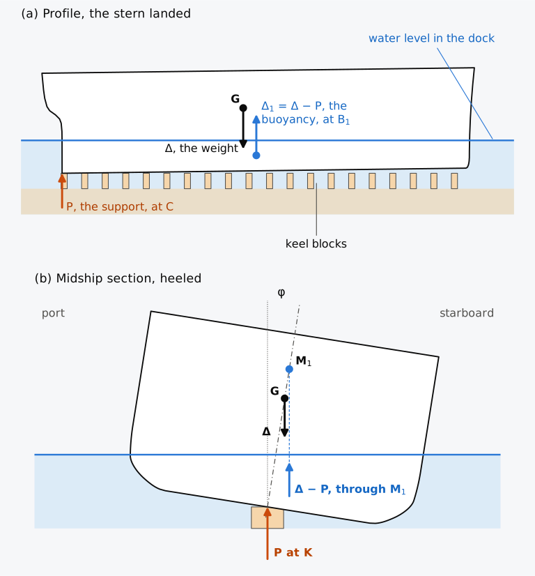
Figure 13.1 The three forces on a ship resting on a block at the after end of its keel: (a) the Series 60 ship at 3407 t, heights three times as large as lengths; (b) its midship section seen from aft, heeled by φ, at true scale. is the metacentre of the waterline at which it floats.
13.1.2 The support as a weight removed
The support relieves the water of a part of the ship’s weight, and as far as the floating position of the ship is concerned the support acts exactly as a weight P removed from the ship at C. The ship rises and trims in the way found in Chapter 6 for a mass discharged at , Eqs. (6.7) and (6.8): a support aft of the centre of flotation F trims it by the head, and a support forward of F trims it by the stern. The force on a docked ship is commonly found in this way, from the change of trim that it produces2,3.
For the stability of the ship, the support can be counted in two ways. It can be kept as a force on a ship whose weight is unchanged, with the whole displacement Δ3, while the buoyancy that holds it up is smaller and acts through the metacentre of the waterline at which it floats4. Since the whole weight is kept, this count is called here the weight basis. The support can also be taken as a weight removed at the point of contact, as in Chapter 5, Eq. (5.2). G then rises to a virtual position , and the displacement falls to the buoyancy that remains3,4, . This count is the buoyancy basis. The weight basis corresponds to the method of lost buoyancy of Chapter 12, which also keeps the weight of the ship, and the buoyancy basis to the method of added weight, which changes it. Those two methods put identical forces on a flooded ship and gave different metacentric heights with a single righting moment, Eq. (12.7). The two bases of a supported ship behave in this way too.
A body that rests on the bottom with no water under part of its surface receives no upward pressure there, and the water above presses it onto the bottom5. Under a ship on keel blocks or on a narrow rock the water reaches almost the whole bottom. The buoyancy of the ship is that of the immersed hull, and the support carries only the difference between its weight and that buoyancy.
13.2 Stability with a support at the keel
13.2.1 The righting moment of a supported ship
Consider the ship of Fig. 13.1(b), supported on its centreline at K, the point of the keel on the baseline, by a support narrow enough to give no resistance to heel, as a keel block or a ridge of rock does. Let it heel through a small angle φ, positive with the starboard side down, about a longitudinal axis. The support stays at K, the weight Δ acts down through G, and the buoyancy acts up through the metacentre of the waterline at which it floats. The height of above the keel, , is the KM of that waterline. Taking moments about K, where P has no moment, the righting moment is
in kN·m, and the upright ship is locally stable while the bracket is positive. For small angles the bracket is the righting moment per radian of heel, called here the righting-moment coefficient. No choice of displacement enters Eq. (13.3), and the two bases follow by rearranging it2,5.
Weight basis. With , and with the metacentric height of the ship at the supported waterline with its real G, Eq. (13.3) can be written
is the effective metacentric height of the supported ship on the basis of the whole displacement. In Fig. 13.2(a) the support P at K and the buoyancy through are replaced by their resultant, a force Δ acting upwards through a point M′ that lies below , and the righting couple is formed by Δ through M′ and Δ through G3.
Buoyancy basis. When P is taken as a weight removed at K, a mass at in Eq. (5.2), G rises to
In Fig. 13.2(b) the weight Δ at G and the support P at K are replaced by their resultant, a downward force at . With the buoyancy through it forms the righting couple3,4.
Multiplying out shows that and both equal the righting-moment coefficient , and the three forms describe a single righting moment. The two virtual losses of metacentric height, on the weight basis and the rise of G, , on the buoyancy basis, are different numbers because they refer to different displacements, as the metacentric heights by lost buoyancy and added weight did in Chapter 12. A metacentric height quoted for a supported ship therefore cannot be interpreted until its basis is stated; the righting moment is unique3.
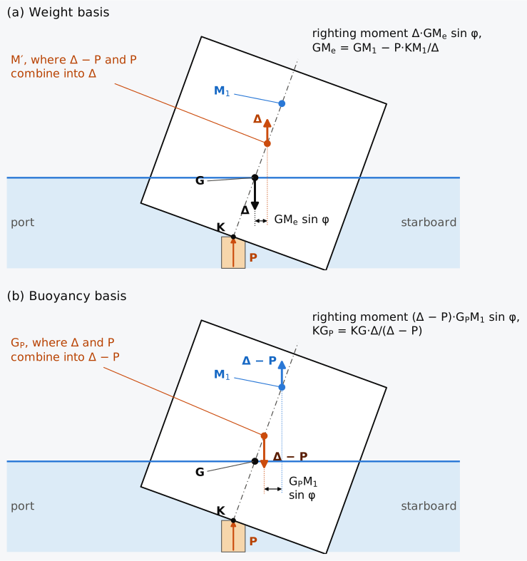
Figure 13.2 The two pairings of the three forces on a section heeled about its keel, heights not to scale: (a) on the weight basis, P and replaced by Δ through M′; (b) on the buoyancy basis, Δ and P replaced by through .
Free surfaces in the ship’s tanks reduce the righting moment on either basis. The free surface moment FSM, a moment of mass in t·m, takes , in kN·m, off the bracket of Eq. (13.3). The correction is on and on , and KG in the three forms may be replaced by the fluid of Chapter 5.
13.2.2 The metacentre of the supported waterline
The metacentre in the three forms of the righting moment is that of the waterline at which the supported ship actually floats. That waterline lies lower than the ship’s free waterline and, for a ship that bears on a line of keel blocks, parallel to the blocks4. Its KM differs from the KM afloat, since KM changes with the draught. On a box of breadth and draught , rises as the draught falls whenever is less than , and on the Series 60 hull at light draughts KM rises steeply, from 7.657 m at a draught of 3.0 m to 9.641 m at 2.0 m (Table 7.2). Taking KM at the free waterline would understate the stability that the supported ship has.
13.2.3 A support above the keel
A launching cradle, or a docking cradle shaped to the hull, bears on the ship above its keel. Suppose that the support acts at a point C of the centreline, a height above K, that it stays at that point of the ship as the ship heels, and that it gives no moment of its own. Its upward force has the lever about K, on the side of the buoyancy, and Eq. (13.3) becomes
A support at the height of G acts as a weight removed at G and leaves as the righting-moment coefficient, and a support at costs no stability. A support at the keel is therefore the least favourable position among such supports at or above K. Treating a cradle as a vertical support at K is conservative within this model; the actual contact and restraints must still be assessed. A support that spreads across the bottom, such as a flat bank or a pair of launching ways, behaves differently, because as the ship heels its reaction moves out towards the side that goes down and resists the heel.
13.2.4 Stability on the keel line and the critical draught
Suppose now that the ship rests on its keel along its whole length, as on the line of keel blocks in a dock or on a long narrow shoal, and that the water falls. The ship can heel about K but cannot trim, and its draught is fixed by the water level. Its buoyancy is that of the hull at the draught on even keel, , and the support force grows as the water falls. By Eq. (13.3) the ship stays upright while , and it becomes unstable at the critical draught , where
Below that draught the ship heels over unless shores, props set against its sides, or bilge blocks hold it5. The critical draught is found by plotting both sides of Eq. (13.7) against the draught and reading where they cross5. A master whose ship has grounded along its keel on a falling tide needs the critical draught to know how much time remains5.
For a box barge of length and breadth that floats freely at , and . Equation (13.7) becomes , which gives
Whenever the barge is stable afloat, lies below . If is less than , the square root has no real value, and the barge remains stable on its keel line down to the smallest draught.
In Fig. 13.3 both sides of Eq. (13.7) are plotted against the draught for a box barge 54 m long and 11 m wide that floats freely at 3.20 m with KG = 4.20 m. As the water falls, the moment of the buoyancy about K, , falls towards the moment of the weight, , which does not change. The gap between the two at any draught is the righting-moment coefficient of the barge on its keel line, and it closes at the critical draught, 2.591 m, the value that Eq. (13.8) gives.
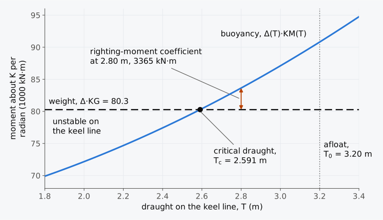
Figure 13.3 The critical draught of a box barge on its keel line, from both sides of Eq. (13.7). The barge is 54 m × 11 m and floats freely at 3.20 m with KG = 4.20 m.
Example 13.1. A box barge on keel blocks. A box barge 54 m long, 11 m wide and 5.5 m deep floats on even keel in sea water at a draught of 3.20 m, with KG = 4.20 m. It is docked on a line of keel blocks under its centreline and lands on them along its whole length. After it has landed, the water level falls by a further 0.40 m. Find the mass carried by the blocks, the metacentric height on the weight basis and on the buoyancy basis, and the righting-moment coefficient, and find the draught at which the barge would become unstable if nothing but the keel blocks held it.
13.3 Docking in a graving dock
13.3.1 The graving dock
The commonest occasion on which a ship rests on a support at its keel is docking, when it is taken out of the water to have its bottom and its underwater fittings inspected and worked on. A graving dock, or dry dock, is a masonry-lined basin in the ground whose entrance can be closed, by hinged gates or a floating caisson, once the ship is inside, and the water is then pumped out. When the dock is dry the ship sits on a line of keel blocks along its floor and is held upright by breast shores between its sides and the dock walls, with further shores under the turn of the bilge and the overhang of the stern2.
13.3.2 The docking plan
Where the ship is to sit in the dock is settled beforehand. Its docking plan gives the stations at which breast shores can bear on the hull, usually where a transverse bulkhead can take their thrust, and the projections that the blocks and the dock entrance must clear, such as propellers that reach below the line of the keel and the bilge keels2. The plan also records the plugs in the ship’s bottom and tanks and the liquids that the tanks may contain6. The tides, draughts and trims at which the ship can be docked are found by comparing the docking plan with the plans of the dock2.
13.3.3 Landing on the blocks
The ship enters upright, with a positive metacentric height and with as few free surfaces in its tanks as can be arranged3,7. In the conventional sequence described by Kemp and Young, a trim of 0.30 m to 1.00 m by the stern is usual7; the actual docking plan determines the entry trim. It is made a little larger than the slope of the block tops, and the after cut-up, the after end of its keel, touches first2. When the ship’s centreline lies over the line of blocks, the shores are placed loosely, the entrance is closed and pumping begins3. As the water level falls, a force builds up at the after end of the keel and trims the ship by the head until the keel bears on the blocks along its whole length. The shores are hardened from aft forward as the ship settles and are all tight by the time the ship takes the blocks overall3, but they are not relied on to hold the ship while it still turns on the after end of its keel. Once the keel bears overall, pumping is stopped until they have been set up firmly7.
The interval between the landing of the stern and the moment at which the keel bears along its whole length is the critical period, and its last moment, the critical instant, is normally the moment of least stability in this sequence before the shores can act3,4. Stability must nevertheless be checked throughout the operation. Until the critical instant the support is concentrated at the after end of the keel, the shores are not yet relied on, and the stability of the ship is that of Eq. (13.3) with P at K. Once the keel bears on all the blocks, the breast shores hold the ship upright2. The force on the blocks keeps growing as the dock is emptied3; adequately designed and secured side supports must then resist overturning. As can be seen from Fig. 13.4, drawn at true proportions for the Series 60 ship, the trim that the support removes, 2.59 m on a length of 121.92 m, turns the keel through only 1.2°. The after end of the keel, where the support acts while the ship pivots, is enlarged in Fig. 13.4(d).
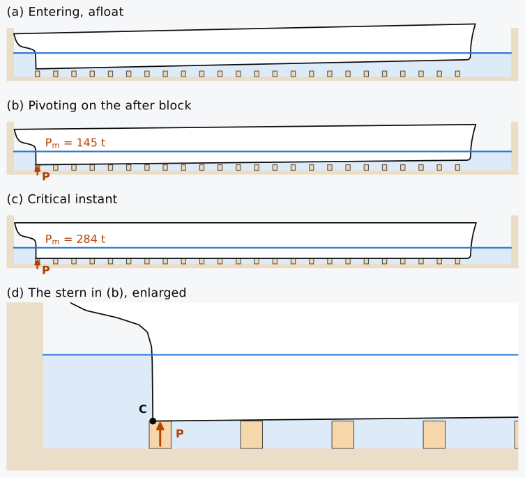
Figure 13.4 The Series 60 ship at 3407 t docking on level blocks, at true proportions: (a) entering, afloat, with 4.95 m of water above the blocks; (b) pivoting on the after block, at 3.63 m; (c) the critical instant, at 2.91 m; (d) the stern in (b), enlarged five times. Computed on the Series 60 hull.
13.3.4 The support force from the change of trim
While the ship pivots on the after end of its keel, the support at C trims it by the head, as a weight removed there would, Eq. (6.7). The moment of the support about the centre of flotation equals MCT 1 cm times the trim lost since the ship landed,
with the trim removed so far, in centimetres, and in tonnes3,7. At the critical instant on level blocks, is the whole trim with which the ship entered the dock; on blocks with a slope, it is the entry trim less the slope of the blocks times the length between perpendiculars.
Which MCT 1 cm belongs in Eq. (13.9) follows from the trims of the two ships that the linear method of Chapter 6 compares. Afloat, the ship trims by centimetres, with and those of its even-keel waterline, Eqs. (6.11) and (4.22). With the support counted as a weight removed at C, the supported ship is a ship of displacement with the virtual of Eq. (13.5), and it trims by centimetres. Here and are those of the even-keel waterline of , and is the height of its longitudinal metacentre above K. The difference of the two moments of buoyancy, , is the moment of the layer of water between the two waterlines, , with the centre of flotation of that layer, and subtracting the two trims gives
At the critical instant on level blocks = 0, and Eq. (13.9) takes : the MCT 1 cm of the ship afloat at entry, built with its own longitudinal metacentric height and its real G, together with the of the layer between the waterline on entry and that of the critical instant. Hydrostatic tables, Table 6.1 among them, give MCT 1 cm with in place of , Eq. (4.23); the value with is smaller by , 2 % for the Series 60 ship, and the table’s value gives a larger P. The MCT 1 cm of the supported ship at the waterline of the moment, , is smaller still, and it governs not the force but its growth: with a trim still to lose, a further centimetre of trim removed adds to . The waterline of the critical instant, and with it and the of the stability, depend on P itself. In practice P is first estimated with the values of the hydrostatic table at the mean draught on entry and then recomputed with those at the draught that this estimate gives2.
Equation (13.9) is linear, with the stiffness of the ship in trim taken at a single waterline. On the way down onto the blocks, however, the ship passes through a range of trimmed waterlines, and with the large trims that light ships sometimes bring into a dock the linear estimate loses accuracy. The exact force at the critical instant follows from the moments about the after end of the keel, Eq. (13.2). On level blocks the waterline at the critical instant is parallel to the keel, and the displacement and the centre of buoyancy of that waterline can be read from the ordinary hydrostatic table; the draught is the draught at which the moment of buoyancy about C equals the moment of the weight about C. Where the blocks have a slope, the balance is made with waterlines parallel to them4.
13.3.5 The Series 60 ship at the critical instant
In Chapter 6 the Series 60 ship discharged all 4300 t of cargo from its departure condition, leaving 3407 t with a trim of 2.59 m by the stern. A ship would not normally bring so large a trim into a dock, and docking it in this light condition shows the limits of the linear method of Sec. 13.3.4. The hydrostatic values of its hull at the light draughts through which it passes in the dock are listed in Table 13.1.
Table 13.1 Hydrostatic values of the Series 60 hull at light draughts, upright and on even keel in sea water (ρ = 1.025 t/m³). and are measured forward of the AP. MCT 1 cm is , with in place of , as in Table 6.1.
| (m) | (t) | TPC (t/cm) | (m) | (m) | MCT 1 cm (t·m/cm) | KM (m) |
|---|---|---|---|---|---|---|
| 2.2 | 2255.7 | 11.95 | 60.050 | 60.25 | 58.99 | 9.087 |
| 2.3 | 2375.6 | 12.03 | 60.060 | 60.23 | 59.56 | 8.849 |
| 2.4 | 2496.2 | 12.10 | 60.068 | 60.21 | 60.10 | 8.632 |
| 2.5 | 2617.6 | 12.17 | 60.074 | 60.18 | 60.63 | 8.434 |
| 2.6 | 2739.6 | 12.23 | 60.078 | 60.15 | 61.14 | 8.252 |
| 2.7 | 2862.2 | 12.29 | 60.080 | 60.12 | 61.64 | 8.085 |
| 2.8 | 2985.5 | 12.35 | 60.082 | 60.09 | 62.13 | 7.932 |
| 2.9 | 3109.3 | 12.41 | 60.081 | 60.05 | 62.61 | 7.789 |
| 3.0 | 3233.7 | 12.46 | 60.079 | 60.01 | 63.08 | 7.657 |
| 3.1 | 3358.6 | 12.52 | 60.076 | 59.97 | 63.55 | 7.534 |
| 3.2 | 3484.0 | 12.57 | 60.071 | 59.91 | 64.03 | 7.420 |
Example 13.2. Docking the Series 60 ship. The Series 60 ship displaces 3407 t, with = 55.270 m and KG = 6.123 m, and has no free surfaces in its tanks. It floats in sea water at = 4.399 m and = 1.812 m and is to be docked on level keel blocks. The after end of its keel, which lands first, lies at = 2.337 m forward of the AP. Using Table 13.1, find (a) the waterline and the mass on the blocks at the critical instant from the moments about the after end of the keel, (b) from the change of trim, Eq. (13.9), with MCT 1 cm as Table 13.1 gives it, and (c) the metacentric height on both bases and the righting-moment coefficient at the critical instant.
13.3.6 The largest trim for a required metacentric height
The force at the critical instant grows with the trim that the ship brings into the dock, Eq. (13.9), and docking trims are kept small for this reason. If a metacentric height of at least is required at the critical instant, the support force may not exceed, by Eqs. (13.4) and (13.5),
and the largest trim follows from Eq. (13.9) with . The two limits of Eq. (13.10) answer two different requirements, because a metacentric height on the buoyancy basis multiplies a smaller displacement. A requirement of this sort has to state its basis. and belong to the waterline of the critical instant, which depends on , and MCT 1 cm to the ship afloat at entry. For a ship this needs a short iteration; for a box barge that waterline follows directly from .
Example 13.3. The largest docking trim of a box barge. The box barge of Example 13.1, 54 m × 11 m × 5.5 m, has a displacement of 1948.32 t, that of a draught of 3.20 m on even keel, and KG = 4.20 m. Its G lies on the centreline but aft of mid-length, and it floats trimmed by the stern. It is to be docked on level keel blocks under its centreline, landing first at its after end. Find the largest trim at which it may enter the dock if the effective metacentric height at the critical instant is to be at least 0.45 m on the weight basis, and the largest trim if is to be at least 0.45 m instead.
13.3.7 After the keel takes the blocks
Once the keel bears on all the blocks, the ship can no longer trim, and every centimetre of fall of the water puts about TPC tonnes more on the blocks. More exactly, the support force at any draught is the weight of the ship less the weight of water it displaces at that draught on even keel3,7, and as a mass
where is the fall in metres since the keel first bore along its length, is the mass already carried by the blocks at that critical instant, and TPC is held at its mean value over the fall. At zero further fall the load is therefore . Equation (13.7) then applies, and if the keel blocks were the only support, the upright ship would lose stability at the critical draught. The breast shores, set tight once the keel bears overall7, and the bilge blocks must be adequate to hold it. A docking calculation therefore covers both the critical instant and the critical draught. In the damage control training of the United States Navy, the pumping out of a dock is stopped just before the critical draught is reached, to check that the side blocks are supporting the ship8.
For the Series 60 ship of Example 13.2, = 3407 × 6.123 = 20,861.1 t·m. From Table 13.1, is 2255.7 × 9.087 = 20,497.5 t·m at 2.2 m and 2375.6 × 8.849 = 21,021.7 t·m at 2.3 m, and the critical draught on the keel line is = 2.2 + 0.1 × 363.6/524.2 = 2.269 m, where the blocks would carry 3407 − 2338.9 = 1068.1 t. Between the critical instant at 2.911 m and the critical draught lies a fall of 0.642 m, during which the shores must be secured. With the free surface moments that the IS Code assumes for the consumable liquids, 1573.5 t·m with the two small tanks left out (Chapters 5 and 11), = 22,434.6 t·m and the critical draught rises to 2.567 m, 0.344 m below the critical instant.
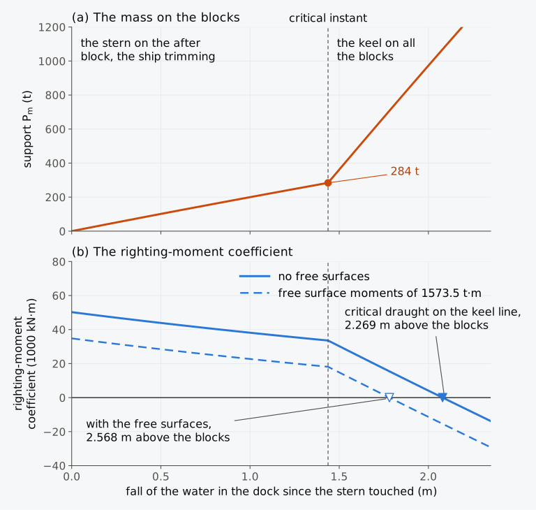
Figure 13.5 The Series 60 ship of Example 13.2 docking on level blocks, against the fall of the water since the stern touched: (a) the mass on the blocks, ; (b) the righting-moment coefficient, with the keel blocks as the only support. Computed on the Series 60 hull.
In Fig. 13.5 the mass on the blocks grows slowly while the ship pivots on its stern, by about 2 t for each centimetre of fall, and then by about 12 t a centimetre once the keel bears along its length. The righting-moment coefficient falls with it, slowly at first and steeply after the critical instant, and with the keel blocks as the only support it would reach zero at the critical draught. The force at the critical instant is small, and the danger of that stage seems to come from the lack of shores during the critical period.
Load on the blocks. When the dock is dry, the whole weight rests on the blocks. Let the keel blocks be spaced evenly along a length with their middle at . If the hull is rigid and the blocks are equally compressible, the load varies linearly along the line, and it must balance the weight and its moment about the middle of the line. The load per metre, as a mass in t/m, is then
and at the two ends it is . All the blocks stay loaded only while does not exceed , the middle-third rule of a footing. Let the Series 60 ship rest on blocks from the after end of its keel, 2.337 m forward of the AP, to 120.0 m, just aft of the point where its forefoot meets the baseline. Then = 117.663 m, = 61.168 m and = 55.270 − 61.168 = −5.898 m. With = −0.30076 the mean load of 3407/117.663 = 28.956 t/m rises to 28.956 × 1.30076 = 37.66 t/m at the after end and falls to 28.956 × 0.69924 = 20.25 t/m at the forward end. In the Surface Forces Logistics Center Standard Specification 8634, Dry Docking, under which the United States Coast Guard docks its cutters, the keel block load is also found as a trapezoid, from the displacement, the supported length of keel and the distance of G from its middle9.
13.3.8 Undocking
Before the dock is flooded again, every bottom plug is replaced, and the tanks are sounded again to confirm that the weights on board are distributed as they were when the ship took the blocks and the first soundings were made7. Weights added, removed or shifted while the ship is in the dock change the support force and the trim at which it lifts off, and they enter the calculation for undocking as they would enter any loading condition.
When the dock is flooded, the sequence of docking runs in reverse. The rising water first takes weight off the blocks along the whole keel. Once the moment of the buoyancy about the after end of the keel exceeds that of the weight, the keel begins to leave the forward blocks while its after end still bears. That instant is again critical7, since the force on the after end of the keel is then the largest of the stage in which the ship pivots. As the water rises further, the force falls and the righting moment grows until the ship floats. For the Series 60 ship of Example 13.2 the righting-moment coefficient, computed on the hull, grows from 33,558 kN·m at that instant (33,546 kN·m by the interpolation of Table 13.1 in the example) to 50,243 kN·m afloat, and the rise can be followed in Fig. 13.5(b) from right to left.
13.3.9 Docking calculator (Calculator 13.1)
With Calculator 13.1 you can follow a box barge or a ship through the critical instant on level blocks. For a box barge you give its length, breadth and depth, the draught that its displacement would have on even keel, KG, any free surface moments and the position of G along it. The calculator finds the trim afloat and the mass on the blocks at the critical instant from the moments about the end that lands first, and beside it from the change of trim. It then gives the metacentric height on both bases and the righting moment, and follows the barge down a further fall of the water to its critical draught on the keel line. For a ship you give its displacement and KG, the trim to be removed, the distance of the after end of its keel aft of F, MCT 1 cm afloat at entry and KM at the waterline of the critical instant; the calculator finds from the change of trim and the stability of the ship on both bases, with these values held constant. It refuses a barge whose end would come out of the water or whose deck would go under, and a case in which the blocks would carry nearly all the weight. Choose Example 13.1, Example 13.3 or an exercise to see the working, or enter your own barge or ship with realistic values.
13.4 Floating docks and ship lifts
13.4.1 The floating dock
A ship can also be lifted out of the water by a dock that floats. A floating dock is a U-shaped box, a pontoon with a wall on each side, a large part of it divided into ballast tanks. The tanks are flooded to sink the dock, and the ship is brought in over the blocks. The dock and the ship are raised together by pumping out the tanks in a sequence that limits the bending of the dock, and with it of the ship2. Floating docks range from small docks that lift less than 500 t to docks that lift ships of up to 100,000 t. A floating dock can be taken to a port that has no graving dock, provided it is kept seaworthy on the passage, and it can be heeled and trimmed to suit the condition of a damaged ship and support the ship partly while its damage is assessed2.
The ship in a floating dock passes through the critical instant and the critical draught of Sec. 13.3 as the dock rises under the ship, and the props or side blocks must be in place before its critical draught is reached5. The stability of the dock itself is high at its operating freeboard, with the pontoon deck above the water, since its waterplane is then that of the whole pontoon. As the dock rises with a ship on its blocks, however, there is a stage at which the water stands between the pontoon deck and the tops of the blocks. The ship is out of the water and the pontoon below the surface, and the waterplane consists only of the two walls, while the weight of the ship stands high on the blocks. This is usually the stage of least transverse stability; a metacentric height of 1.0 m to 1.5 m is commonly accepted for it, and some operators ask for twice as much in the practice described by Tupper2. For comparison, the 2022 rules of the American Bureau of Shipping for steel floating docks ask for the stability of a dock to be calculated with the tops of the keel blocks breaking water and with the top of the pontoon at the water level, and for a metacentric height of the dock and the ship together, after correction for free surfaces, of at least 1.525 m for docks of up to 10,200 t lifting capacity10.
Example 13.4. A floating dock lifting a barge. A floating dock 70 m long and 19 m wide consists of a pontoon 3.0 m deep and two wing walls, each 2.2 m wide, which run the whole length of the dock and rise to 10 m above its bottom. The dock’s lightweight is 1600 t with its centre of gravity 3.40 m above its bottom. It lifts a box barge 54 m long and 11 m wide, of 1948.32 t with KG = 4.20 m above its keel, which rests on keel blocks 1.4 m high and is held by side blocks, and dock and barge move together. The ballast that remains in the dock at each stage lies in full compartments of the pontoon with its centre at mid-depth, 1.50 m above the bottom, and there are no free surfaces. Find the metacentric height of the dock and the barge together in sea water when the water stands (a) at the tops of the keel blocks, (b) at the pontoon deck, before the deck comes out of the water, and (c) 0.30 m below the pontoon deck. All heights are measured from the bottom of the dock.
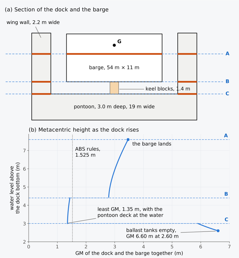
Figure 13.6 The floating dock and the barge of Example 13.4: (a) a section at true scale, with three water levels and the waterplane at each as thick bars; (b) the metacentric height of the dock and the barge together against the water level. The dotted line is the least value in the rules of the American Bureau of Shipping (ABS)10.
13.4.2 Ship lifts and building docks
A ship lift raises a ship vertically out of the water on a platform carried by wire-rope hoists along both sides. A load-monitoring system keeps the loads within what the ship and the platform can bear, and a cradle is shaped to the hull2. The capacity of a lift is stated as the largest load per metre along the centreline of the platform, and the ships that it can lift depend on how their weight is distributed along their length. Many lifts serve ships of about 1000 t, and some are built for 30,000 t or more; a transfer system ashore lets a single lift serve several berths2. The ship is lifted on a cradle or on blocks, and while the platform rises through the water the ship passes through a critical instant of its own, as it does in a dock.
A ship built in a building dock floats out of it in the way a docked ship undocks, and the ship’s least stability on the way comes when its keel has begun to leave the blocks at one end while the other end still bears on them.
13.5 Grounding
A grounding, unlike a docking or a launch, is not planned, and how the ship fares depends on the tide, the weather and the seabed. The stability of the ship depends above all on where it touches, along its length and across its bottom2. If its bottom is punctured, the flooding treated in Chapter 12 acts together with the reaction of the ground, and the residual strength of the damaged hull must be assessed as well2. A ship whose hull is still intact is a partly supported ship, like the docked ship of Sec. 13.3.
13.5.1 Aground at a point and along the keel
A ship that drives onto a bank or a rock may lift itself partly out of the water with the energy of its forward motion, and the bottom carries the difference between its weight and its buoyancy; as the tide ebbs, this reaction grows4. Where the ship touches over a small area of a smooth bottom, or rests on a rock with its hull intact, the reaction acts on it as the support of a docked ship does, with two differences. It need not act on the centreline, and it changes with the tide and with any waves. Its value is the force that brings the draught at the point of contact to the depth of water there, heeling the ship as well as trimming it when the contact lies off the centreline2. A ship stranded at the bow or the stern takes up the trim at which the moments of its weight and its buoyancy about the point of contact are equal4, the condition of Eq. (13.2).
A ship aground on a single point of its keel trims about that point as the water falls. With moments taken about a horizontal line through the contact, it is stable while a point that plays the part of the metacentre lies above G5. By similar triangles and Eq. (13.2), that point lies at times the height of above the line through the contact. On a nearly level keel it is the point M′ of Fig. 13.2(a), and the condition is again that the bracket of Eq. (13.3) be positive.
A ship aground along its whole keel, on a shoal or a sandbank that is narrow compared with its breadth, cannot trim, and its draught falls with the water. As in Sec. 13.2.4, it loses stability upright when the water falls below its critical draught unless the ground gives it support away from its keel5. Whether it then finds a heeled equilibrium, meets further ground support or capsizes depends on the large-angle moments and contact.
13.5.2 The falling tide
Let an intact ship touch a narrow support under its keel at at high water and stay there while the water falls by a height . The support must hold the point C of the keel at the level of the bottom, so the ship’s draught at C falls by exactly . The support acts as a mass removed at C. As in Chapter 6, the ship rises bodily by centimetres and trims by centimetres, by the stern if C lies forward of F. The draught at C changes by the sum of the rise and the part of the trim that falls at C, Eqs. (6.7) and (6.8), and setting this change equal to gives
with in metres, TPC in t/cm, MCT 1 cm in t·m/cm and the length between perpendiculars. A ship that touches from even keel has = 0 in the relation of Sec. 13.3.4, and the MCT 1 cm here is , that of the ship with the support counted as a weight removed, at the waterline of the moment. For a small fall it equals the ship’s own , 85.34 t·m/cm for the Series 60 ship at 7707 t computed on the hull, and the value that Table 6.1 gives with in its place, 86.88 t·m/cm, is about 2 % larger. The first term of the denominator is the rise of the whole ship and the second the rise of C from the trim, which grows with the square of the distance of C from F. A support near F therefore takes weight quickly, since the ship can rise there only bodily. A support near either end lets it trim, and the force grows slowly.
The Series 60 ship in its fully loaded departure condition displaces 7707 t, with KG = 5.887 m and the free surface moments that the IS Code assumes for its consumable liquids, 1573.5 t·m, and floats on even keel at 6.366 m. Table 6.1, interpolated at 7707 t, gives TPC = 14.30 t/cm and = 56.43 m, and at that waterline KB = 3.417 m and = 137.47 m, so that = 7707 × (3.417 + 137.47 − 5.887)/(100 × 121.92) = 85.34 t·m/cm. By Eq. (13.13), grows by 2.85 t for each centimetre of fall with the support at the after end of the keel, 2.34 m forward of the AP, by 14.05 t/cm with the support at 60 m, and by 2.18 t/cm with the support under the forefoot at 120 m.
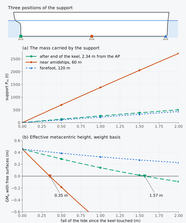
Figure 13.7 The Series 60 ship at 7707 t aground on a narrow support at three positions along its keel as the tide falls: (a) the mass carried by the support, ; (b) the effective metacentric height, with free surfaces. In the strip above, heights are twice as large as lengths. Computed on the hull with the trim free.
Figure 13.7(a) shows that computed on the hull grows almost linearly with the fall. After a fall of 2.0 m it is 438 t with the support under the forefoot, 0.5 % more than Eq. (13.13) gives, and 2716 t with the support at 60 m, 3 % less. With the support at the after end of the keel it is 503 t, 12 % less. There the ship trims by the head, 3.58 m at that fall, its centre of flotation moves forward, away from the support, and both TPC and MCT 1 cm fall. The mass on that support grows by 2.85 t for each centimetre of fall at first and by 2.30 t at the end.
The three positions differ far more in their effect on the stability, plotted in Fig. 13.7(b). Near amidships, where the ship can hardly trim, rises by 14 t for every centimetre, and the ship’s effective metacentric height falls to zero after a fall of only 0.35 m. A support at the after end of the keel takes weight five times more slowly, and the metacentric height remains positive until the tide has fallen 1.57 m. Under the forefoot grows at a similar rate, but the ship trims by the stern. Its waterline widens aft and its KM rises, and after a fall of 2.0 m it still has a metacentric height of 0.227 m.
Example 13.5. Aground at the forefoot on a falling tide. The Series 60 ship in its fully loaded departure condition displaces 7707 t, with = 59.207 m, KG = 5.8865 m and the free surface moments that the IS Code assumes for its consumable liquids, 1573.5 t·m, and floats on even keel at 6.366 m, where TPC = 14.30 t/cm, = 56.43 m, KB = 3.417 m and = 137.47 m; = 121.92 m. At high water its keel touches a pinnacle of rock 120.0 m forward of the AP, under its forefoot, and the tide then falls 1.50 m. (a) Find the mass carried by the support and the draughts by Eq. (13.13). (b) Computed on the hull at the waterline at which it then floats, = 7378.80 t and = 6.6462 m; find its metacentric height on both bases and the righting-moment coefficient.
13.5.3 An off-centre contact
If the support acts a distance from the centreline, positive to port, its moment heels the ship away from it. An equilibrium heel is possible where the moments of its weight and its buoyancy about the point of contact are equal4; it must also be stable. For small angles, with heel φ positive with the starboard side down, the moments about K give
with P, and taken at the waterline at which the ship rests. The denominator is the righting-moment coefficient of Eq. (13.6). If the falling tide increases P and reduces this coefficient, the heel grows faster than the force. The coefficient depends also on the waterline and its KM; its decrease is not automatic. The small-angle estimate ceases to be reliable as the heel grows.
13.5.4 A ridge, a flat bottom and mud
The keel-line model of Sec. 13.2.4 assumes that the ship can heel about its keel, which is true on keel blocks, on a ridge of rock or on a pinnacle. Broad, firm contact with a flat bottom can restrain transverse heel; a narrow peak well above the surrounding bottom provides much less restraint4. Uneven contact, damage and a changing tide still have to be assessed. On a ridge the support stays at the keel as the ship heels, Fig. 13.8(a). On a flat hard bottom the ship must lift one bilge off the ground to heel, and the support moves out to the bilge that stays on it, where its moment resists the heel, Fig. 13.8(b). The United States Navy’s handbook for salvors describes the ground under a ship hard aground as acting like the cradle of a dry dock, which supports it against listing, while the reaction causes a virtual rise of G11.
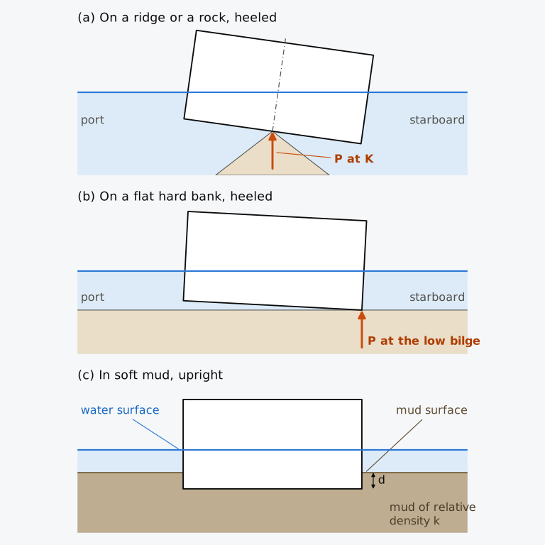
Figure 13.8 A box barge seen from aft: (a) heeled on a ridge, with the support at the keel; (b) heeled on a flat hard bank, with the support at the low bilge; (c) upright in soft mud, sunk to a depth .
A ship that settles on soft mud at a berth as the tide falls is a third case2. Let the mud be treated as a heavy liquid whose density is times that of the water above it. A wall-sided barge of draught whose keel has just touched the mud then sinks into it by when the water falls by . Its weight is carried by the water displaced above the mud, of depth , and by times the mud displaced, of depth , and . Heeled slightly, the barge transfers a wedge of water at the water surface and a wedge of mud at the surface of the mud. The mud wedge displaces mud where there would otherwise be water, and it transfers times the buoyancy of a wedge of water of equal volume. For a wall-sided barge the two surfaces have equal second moments , and the two transfers together act as . The moments about the keel of the water and the mud displaced give the centre of buoyancy2,
with ∇ the volume of displacement afloat. Mud of relative density 2 doubles BM while it holds the barge, and a barge that touches mud may be stiffer than when afloat. The model is idealized2, since mud does not behave as a liquid. A hull that lies in mud with no water under part of its bottom is also pressed down by the water above, Sec. 13.1.2, and seems to be held by suction until water reaches beneath it5. The two-liquid reasoning applies to a hull of any section, with the second moments of the hull at the two surfaces in place of a single .
13.5.5 The support force from the draughts
When a ship is aground, its draughts read at the marks give the waterline at which it floats, and its hydrostatics at that waterline give and . By Eq. (13.1), the force on the ground is the displacement before the grounding less the displacement at the observed waterline3. Its position follows from Eq. (13.2), with the levers measured horizontally. A ship aground is often trimmed several metres. A point of the ship at and a height then lies a horizontal distance forward of the AP, where θ is the trim angle, positive bow up, with . The factor is common to every lever and cancels, and for a contact on the baseline Eq. (13.2) becomes
For the ship of Example 13.5, with = 7.243 − 4.829 = 2.414 m, = 0.01980, = 7378.8 t, = 56.447 m and = 3.320 m on the hull, Eq. (13.16) gives the position of the support as 120.0 m, where the pinnacle is. With the levers measured along the ship, the balance would put it 1.26 m further forward. If the position found lies outside the part of the bottom that can be in contact, the assumed contact is wrong.
13.5.6 Exploring the falling tide (Explorer 13.1)
In Explorer 13.1 you can place a narrow support anywhere along the keel of the Series 60 ship in its departure condition and let the tide fall by up to 2 m. The explorer gives the mass carried by the support, , the draughts at the perpendiculars, , the effective metacentric height with free surfaces and the righting-moment coefficient, and it marks the fall at which that metacentric height reaches zero for the chosen position. Its values were computed on the hull every 5 m along the keel and every 0.1 m of fall, with the trim free, and are interpolated linearly between those points. Try moving the support from the forefoot towards amidships and back to the stern, and watch how the fall that the ship can bear changes.
13.6 Refloating
13.6.1 Lightening, shifting weight and the neutral point
A ship aground floats again when the support force P falls to zero. The rising tide does this at the rate of Eq. (13.13), and the master can also change the ballast and loading to lift the ship clear2. Removed from the ship afloat, a mass at would lift the point C of its keel by centimetres, through the bodily rise and the part of the trim that falls at C. Aground, C cannot rise. The support force falls instead, by the force that would lift C by as much if it were counted as a weight removed at C, Eq. (13.13). The mass carried by the support, , therefore falls by the fraction η of the mass removed,
A mass removed at the point of contact reduces by its whole amount, . A mass removed at the position where leaves unchanged; this is the neutral point of the contact, at which a load leaves the draught at C unchanged, Eq. (6.9) with ,
A mass removed beyond the neutral point, on the far side of F from the contact, increases , since it trims the ship down at the contact by more than it lightens the ship. Shifting a weight from near the contact to a position beyond the neutral point reduces by more than the weight moved, and taking ballast into a tank beyond the neutral point reduces although it makes the ship heavier.
Example 13.6. Refloating a ship aground at its forefoot. The Series 60 ship, 7707 t, is aground on a pinnacle under its forefoot, 120.0 m forward of the AP, with the tide 1.50 m below the level at which it touched, and carries = 327.3 t there by Eq. (13.13), with TPC = 14.30 t/cm, = 56.43 m, MCT 1 cm = 85.34 t·m/cm, the ship’s own value built with , and = 121.92 m. Hold 1 contains 271 t of cargo with its centre 105.68 m forward of the AP, hold 2 contains 693 t at 91.28 m and hold 5 contains 848 t at 20.90 m. Using Eqs. (13.17) and (13.18), find (a) the neutral point, (b) the cargo that must be discharged to refloat it at this state of the tide, taking all of hold 1 first and the rest from hold 2, and (c) the effect of discharging 100 t from hold 5 instead.
13.6.2 Freeing a stranded ship
In the idealized narrow-contact case discussed by Moore, a hull may slide off a peak when the slope of its bottom exceeds the angle of friction between hull and support4. This is not a general assurance against capsize: impalement, obstructions, damage and stability after release can change the outcome. Moore also discusses how a low tow-line attachment reduces the heeling moment near the limit of stability4. The actual release sequence requires a salvage assessment of contact forces, structural strength, flooding and stability both aground and afloat.
Lightening a stranded ship, as in Sec. 13.6.1, frees it only when the lightening is timed with the tide and the salvage gear, and until then the ship is better held still. In the damage control training of the United States Navy, a stranded ship is not to be driven off under its own power when wind and sea may work it harder aground; in most strandings anchors are laid to seaward, and the ship is weighted down rather than lightened to keep it from working on the bottom8. The Navy’s handbook for salvors adds that a rising tide reduces the ground reaction and may leave a ship whose stability has been reduced lively and in danger of capsizing, and that ballasting the ship down until the tide serves should be considered11.
When the tanker Exxon Valdez ran onto Bligh Reef in Prince William Sound in March 1989, its chief mate ran his computer program again in another way and concluded that the ship did not have acceptable stability without the support of the reef. He recommended that it should not leave the area. The master had meanwhile put the engine ahead again at about 12.35 a.m., eventually to full ahead, in an attempt to free the ship, and he kept the engine running until 1.41 a.m.12. Had the ship come off the reef, it would have lost the support on which, by the chief mate’s calculation, its stability depended.
The car carrier Hoegh Osaka developed a heavy list to starboard shortly after leaving Southampton on the evening of 3 January 2015, lost steering and propulsion and drifted onto Bramble Bank, where it lay with a list of about 40° to starboard13. The pilot stressed that it was important that the ship remain on the bank, and tugs pushed it further onto the bank and held it there13. As the tide fell, the ship’s list slowly increased13. It was refloated at high water on 7 January, and the salvors left the water that had entered the ship on board for a time because the water improved its stability13.
Neither ship rested on the narrow support of Secs. 13.5.1 and 13.5.2. Each lay on a reef or a bank over part of its bottom, the broad support of Sec. 13.5.4, whose reaction moves out to the low bilge as the ship heels and resists the heel. On such a support, a ship whose stability afloat is in doubt may be safer aground than afloat.
13.7 Launching
Docking and grounding bring a ship from the water onto a support. A launch takes it the other way, from the land into the water, and on the way it passes through stages in which part of its weight rests on the ways and the rest on the water.
13.7.1 Methods of launching
In an end launch down inclined ways, the stern usually enters first2. Large ships are often built in building docks instead, and their launch is an undocking of an incomplete ship. The weights built into such a ship must be assessed with care to find its displacement and the position of G before it floats out. Weight may have to be adjusted to keep it from floating with an excessive trim or heel, and it may need temporary strengthening2. A yard on a narrow river may launch its ships sideways. The ship is built on a level keel parallel to the bank, and at the launch it slides down ways at right angles to its keel, which tilt at their outer end and drop it into the water. The ship is sent off fast, to clear the ways before it rolls back towards them. It raises a large wave and rolls heavily, and openings that might be immersed are closed beforehand2.
13.7.2 The slip, the ways and the cradle
A ship launched end on slides into the water on a cradle. The cradle is built under it just before the launch and rests on sliding ways, which run on two greased groundways laid on the slip, parallel to the keel and about a third of the beam apart2. Where the hull rises towards the bow and the stern, the cradle is built up into the fore and after poppets. The sliding ways need enough area to keep the pressure on the grease, up to about 20 t/m² (about 196 kPa), from squeezing it out2. Until the cradle takes the weight, the ship stands on a line of building blocks under its keel, typically about 1.5 m high. They are set vertically rather than square to the slip, to make them less likely to be knocked over, and they leave room for work on the bottom, for putting the cradle in place and for keeping the forefoot clear of the slip during the launch; shores support the bilges and overhangs2. The floor of the slip, at about 1 in 20, slopes towards the water2.
The slope of the groundways, their declivity, must be steep enough for the component of the weight down the ways to overcome the starting resistance of the grease, and later the resistance of the grease and the water, but not so steep that the ship enters the water too fast. The slope of the lower stretch also sets how quickly the buoyancy and its moment about the fore poppet build up. The ways are often given a camber along their length as a compromise between these requirements2. At the launch the last shores are removed and a trigger is released, and hydraulic rams push the ship if its weight does not set it moving2. The ship is still moving fast when it is afloat. Water brakes built over its propellers and drag chains, brought into action one after another as it leaves the slip, slow the ship down before tugs take it to the fitting-out berth2.
13.7.3 The stages of an end launch
The weight and the position of G at the launch come from a detailed record of the material built into the ship, often supported by weighing2. The launch is calculated as a quasi-static operation, in which the forces and moments are taken to balance at every position. The profile of the ship is moved step by step down the profile of the ways and the waterline is drawn at each position. The buoyancy and its centre are found at that waterline from the Bonjean curves2, as in Sec. 7.7.1.
While the ship slides with its keel parallel to the ways, the stern enters the water first. The buoyancy of the immersed part grows, and the ways carry the rest of the weight, , spread along their length. After a certain travel G passes beyond the after end of the ways (AEW). The weight of the ship then has a moment about the AEW that would turn its stern down over the end of the ways and lift its bow off them, a motion called tipping. The buoyancy has an opposing moment about that point, and if and are the horizontal distances of G and seaward of the AEW, the ship does not tip while
A ship that tipped would bring the whole support onto the end of the ways. Its bottom might be forced in or the end of the ways give way, and if it stopped on the ways it would be in a dangerous state as the tide fell14. The difference between the two moments is the moment against tipping, and its least value along the travel is the margin of safety. A ship with too small a margin is given longer ways or ballast right forward, either of which delays the point at which G passes the AEW. Ships have been launched safely with an adverse tipping moment, however, because their speed carried them past it14.
Further down the ways the moment of the buoyancy about the fore poppet grows until it equals the moment of the weight about that point,
where and are the horizontal distances of G and aft of the fore poppet. The stern then lifts, and the ship turns about the fore poppet, which carries the difference between the weight and the buoyancy, Eq. (13.1), concentrated over a short length of the ship and of the slip2,14. This is the largest force on the fore poppet and may be about 20 % of the weight2. The hull, its internal shoring and the slip under the poppet must be strong enough to bear it14. The ship is now a partly supported ship with its support at the fore poppet, and its stability at this stage is found as for docking2.
As the ship travels on, the buoyancy keeps growing and the force on the poppet falls. If the buoyancy reaches the weight before the fore poppet reaches the end of the ways, the ship floats off. Otherwise its bow drops off the end of the ways, and the water there must be deep enough for the drop, bearing in mind that dynamic effects make the actual drop greater than the drop that the final forward draught implies2.
These results are drawn against the travel down the ways as the launching curves: the weight, which is constant; the buoyancy; the moment of the weight about the fore poppet, which is effectively constant; the moment of the buoyancy about the fore poppet; and the moments of the weight and of the buoyancy about the AEW2. The stern lifts where the two moments about the fore poppet meet, and the force on the poppet at that travel is the gap between the weight and the buoyancy. The gap between the two moments about the AEW is the moment against tipping14.
Historical note: launching curves
13.7.4 The launch of the Series 60 ship
The Series 60 ship is launched here at the lightship mass of Table 3.1, 2850 t with = 57.58 m and KG = 6.85 m. The lightship is an assumption for this example. Where fitting-out continues after launch, the actual launching weight is generally below the completed lightship weight2; it depends on the construction stage. The ways are straight, with a declivity of 1 in 20, the keel lies 1.2 m above them on the cradle and the sliding ways, and the fore poppet bears on the ways under the point of the keel 106 m forward of the AP. The after end of the ways lies 3.0 m below the water at the tide of the launch. The travel is measured from the position at which the AP lies 60 m up the ways from the AEW, and the ship keeps the slope of the ways, a trim angle of 2.86° by the stern, until its stern lifts. At each position the buoyancy and its centre were computed on the hull at the waterline of that position. Afloat in this condition the ship would float at 3.269 m aft and 2.091 m forward, with GM = 1.298 m. The calculation is a balance of masses, in t, and of their moments, in t·m, which are the moments of the forces divided by . The moments are taken about the point at which the fore poppet bears on the ways and about the AEW, both on the ways, 1.2 m below the keel, with the levers measured horizontally. With = 1/20, G lies 106 − 57.58 = 48.42 m aft of the fore poppet along the keel and 6.85 + 1.2 = 8.05 m above the ways, so the lever of the weight about the poppet is 48.42 cos θ + 8.05 sin θ = 48.7616 m and its moment, divided by , 2850 × 48.7616 = 138,971 t·m while the ship lies on the ways. At a travel of 100 m, where G lies 17.58 m landward of the AEW along the ways, the lever about the AEW is −17.58 cos θ + 8.05 sin θ = −17.1561 m and the moment −48,895 t·m. The buoyancy at six positions of travel and the moments about the fore poppet and the AEW, from which the stern lift and the margin against tipping are found, are listed in Tables 13.2 and 13.3.
Table 13.2 Launching calculation of the Series 60 ship at 2850 t, = 57.58 m and KG = 6.85 m, on ways of 1 in 20 with the after end of the ways (AEW) 3.0 m below the water: the buoyancy as a mass, in t, and the moments of the weight and the buoyancy about the fore poppet, divided by , in t·m. The row for 130 m gives the values that the ship would have if it still lay on the ways.
| Travel (m) | (t) | Weight | Buoyancy |
|---|---|---|---|
| 100 | 993.8 | 138,971 | 68,142 |
| 110 | 1432.2 | 138,971 | 93,357 |
| 115 | 1677.1 | 138,971 | 106,859 |
| 120 | 1936.6 | 138,971 | 120,833 |
| 125 | 2208.8 | 138,971 | 135,214 |
| 130 | 2492.5 | 138,971 | 149,959 |
Table 13.3 Moments of the weight and the buoyancy about the AEW, divided by , in t·m, for the Series 60 ship launched at 2850 t on ways of 1 in 20 with the AEW 3.0 m below the water. A moment about the AEW is positive for a force acting seaward of it, where the weight tends to tip the ship and the buoyancy resists tipping; the moment of the weight is negative while G lies landward of the AEW. The row for 130 m gives the values that the ship would have if it still lay on the ways.
| Travel (m) | Weight | Buoyancy |
|---|---|---|
| 100 | −48,895 | 2632 |
| 110 | −20,430 | 13,253 |
| 115 | −6198 | 21,432 |
| 120 | 8034 | 31,862 |
| 125 | 22,266 | 44,766 |
| 130 | 36,499 | 60,342 |
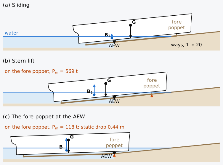
Figure 13.9 The end launch of the Series 60 ship at 2850 t on ways of 1 in 20, heights twice as large as lengths: (a) sliding, with G still landward of the AEW; (b) the stern lift, when the ship begins to turn about the fore poppet; (c) the fore poppet at the AEW. Computed on the Series 60 hull.
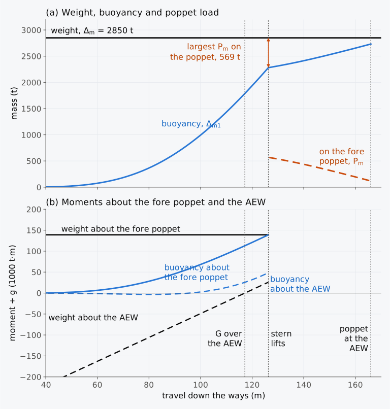
Figure 13.10 Launching curves of the Series 60 ship at 2850 t: (a) the weight, the buoyancy and the load on the fore poppet, as masses in t; (b) the moments of the weight and of the buoyancy about the fore poppet (solid) and about the AEW (dashed), divided by , in t·m. Computed on the Series 60 hull.
As can be seen from Fig. 13.10(b), G passes over the AEW after a travel = 117.18 m, and from then on the moment of the weight about the AEW grows linearly with the travel. The moment of the buoyancy about that point grows faster, however, and the moment against tipping, divided by , is least, 22,500 t·m, after about 125 m of travel, shortly before the stern lifts. The stern lifts after a travel = 126.29 m, with 2280.7 t carried by the water and 569.3 t, 20.0 % of the weight, on the fore poppet. The ship then turns about the poppet, Fig. 13.9(b), and the force on it falls as the buoyancy grows. When the poppet reaches the AEW, after 166 m of travel, it still carries 118.1 t, Fig. 13.9(c). Afloat, the point at which the poppet bears on the ways would lie 3.445 m below the water, against the 3.0 m of the AEW, and the bow drops at least 0.445 m off the end of the ways. The launch from 60 m of travel up to this drop can be followed in Animation 13.1.
Animation 13.1 The end launch of the Series 60 ship at 2850 t on ways of 1 in 20, from 60 m to 166 m of travel, with the ship in equilibrium at each position. In the graph the weight, the buoyancy and the load on the fore poppet are drawn as masses, in t. No sound; 18 s.
Example 13.7. Launching curves of the Series 60 ship. The Series 60 ship, 2850 t with = 57.58 m and KG = 6.85 m, is launched down ways of 1 in 20, and Tables 13.2 and 13.3 give its launching calculation. Find (a) the travel at which G passes over the AEW, (b) the moment against tipping, divided by , after 120 m and 125 m of travel, and (c) the travel at which the stern lifts, with the buoyancy and the mass carried by the fore poppet at that travel, by linear interpolation in the tables. (d) Computed on the hull at the stern lift, = 2280.7 t and = 9.254 m. Taking the force on the fore poppet as acting at K, find the metacentric height on both bases and the righting-moment coefficient.
13.7.5 Stability in the launching condition
At its launch a ship is light, and its centre of gravity stands high above its keel. Attwood14 recorded the suggestion of a metacentric height of at least 1 ft (0.30 m) in the launching condition, to be obtained by ballasting where the estimate fell short, and advised that the curve of righting levers be drawn from the cross curves in any case of doubt. The case that drew special attention to the matter was the loss of the steamer Daphne on the Clyde14.
Historical note: stability before launching
The Daphne, a steamer built by Alexander Stephen and Sons, was launched on 3 July 1883 with an unusually large number of workmen on board15. Having moved scarcely its own length from the shore, it turned over onto its port side and sank in less than three minutes16; 124 men and boys were killed17. As McGee18 reports Sir Edward J. Reed’s inquiry, the owners’ plans had been drawn by a marine engineer without training in naval architecture, who had added heavy lifting machinery and deckhouses to an earlier design, raising the centre of gravity, and had never thought of calculating the ship’s stability. Francis Elgar, engaged by the builders, found that the ship had so little stability that almost any small disturbance would have capsized it18. The builders’ history presents the inquiry and their exoneration as a turning point: since the disaster, it says, builders have always estimated the stability of a ship before launching it15.
Afloat at 2850 t the Series 60 ship has GM = 1.298 m, but at the stern lift, with 569.3 t on the fore poppet, its effective metacentric height on the weight basis is 0.555 m. Since that basis keeps the whole displacement, the righting moment of the ship is less than half of what it is afloat, and an estimate of stability at launch has to follow the launch stage by stage.
Now that the stages of a launch have been followed, we can go back to the Baaden. At its first roll the yacht was still carried mainly by the aft cradle, whose wooden blocks held the hull on both sides, and the heel probably came from that cradle dropping to port as its tyres ran off the side of the upper ramp1. Before its final roll the yacht had been backed off that cradle with its stern afloat, and the forward end of its keel rested in the small forward cradle, which did not keep it from rolling1. As the Board’s brief describes this stage, the large trim of a ramp launch makes the stern buoyant while the bow rests on a cradle, with a possible interval of negative righting lever1. The support on the centreline near the keel links this stage qualitatively to Sec. 13.2.3, where a narrow, low support reduces the righting moment; Eq. (13.4), with its small-angle and nearly level-keel assumptions, is not a numerical reconstruction of this casualty on an inclined ramp. A centre of gravity to port of the centreline gives a list that, at small angles, grows as the effective GM falls, provided that a stable equilibrium at a small angle still exists. The yacht’s margin of stability had been small before launch, since the reading of the aft starboard load cell had been recorded wrongly and its ballast overestimated1. No calculation had been made of its stability on the inclined ramp. The naval architect who had calculated its stability recommended a positive range of stability of at least 30° for a ramp launch1. The recommendation was made for this launch and is not a general launching criterion.
As can be seen from Table 13.4, docking, grounding and launching differ in where the support acts and in the stage at which the ship is checked, but each is judged by the righting moment of Eq. (13.3).
Table 13.4 Docking, grounding and launching compared. is the metacentric height on the weight basis, referred to the whole displacement Δ, Eq. (13.4); is that on the buoyancy basis, referred to Δ − P, Eq. (13.5).
| Operation | Treatment |
|---|---|
| Where the support acts | |
| Docking | At the after end of the keel, then along the whole keel (Sec. 13.3.3) |
| Grounding | At the point of contact, on or off the centreline (Secs. 13.5.1 and 13.5.3) |
| Launching | Along the ways, then at the fore poppet once the stern lifts (Sec. 13.7.3) |
| How its force grows | |
| Docking | With the trim removed, Eq. (13.9); then grows by about TPC tonnes per centimetre of fall, Eq. (13.11) |
| Grounding | With the fall of the tide, fastest for a support near F, Eq. (13.13) |
| Launching | On the poppet, largest at the stern lift and falling as the buoyancy grows (Sec. 13.7.3) |
| Stage checked | |
| Docking | The critical instant, the last before the shores can act (Sec. 13.3.3); the critical draught, Eq. (13.7) |
| Grounding | The fall at which vanishes, least for a support near F (Fig. 13.7(b)); along the keel, Eq. (13.7) |
| Launching | The stern lift, Eq. (13.20), after G has passed the end of the ways without tipping, Eq. (13.19) |
| Measure of stability | |
| Docking | and (Example 13.2); in the specification of Sec. 13.8 |
| Grounding | with free surfaces (Fig. 13.7(b)); both bases in Example 13.5 |
| Launching | and , with the force on the poppet taken at K (Example 13.7) |
| Limit cited | |
| Docking | Largest trim on entry for a required GM, Eqs. (13.9) and (13.10); draught at landing at least 0.30 m above that at instability (Sec. 13.8) |
| Grounding | No universal limit given here. On a narrow centreline support with no heeling moment, positive establishes local upright stability (Sec. 13.5.1); an off-centre contact heels it (Sec. 13.5.3) |
| Launching | Historical guidance: GM of at least 0.30 m, recorded in 1899. Case-specific advice: range of at least 30° for the yacht’s ramp launch (Sec. 13.7.5). Neither is a general approval criterion. |
13.8 Docking, grounding and launching in industry today
This section describes practice in 2026. Its web pages were read from 19 to 21 October 2026, and MSC.1/Circ.1348 on 4 November 2026.
Docking intervals. The International Convention for the Safety of Life at Sea, 1974, as amended (SOLAS), requires every cargo ship to which the Convention applies to have the outside of its bottom inspected at least twice in any five-year period, with no more than 36 months between two inspections19, and a passenger ship to have the outside of its bottom included in a renewal survey every twelve months19. For passenger ships aged 15 years or less, other than ro-ro passenger ships, MSC.1/Circ.1348 gives guidance for accepting an in-water survey in place of an inspection in dry dock. With the Administration’s acceptance, this permits one dry-dock examination in any five-year period, with no more than 60 months between consecutive dry-dock inspections; the annual bottom inspection still applies20. Docking is expensive, and hull coatings that stay effective for longer, cathodic protection and repairs carried out afloat have made it less frequent than it was2.
Docking calculations. The United States Coast Guard’s Standard Specification 8634 asks for at least three sets of calculations, the first before the contract is awarded, the second for docking and the third for undocking, each prepared by a naval architect or a certified dockmaster or under the supervision of a professional engineer9. In the docking set, the draught at landing is found from the reaction on the after end of the keel, and the metacentric height at landing with the virtual KG of the buoyancy basis9. For the draught at instability, hydrostatic data are taken at mean draughts from 1 ft (0.30 m) above to 2 ft (0.61 m) below the mean draught on docking, and the reaction on the after end of the keel is recomputed for each. At each draught, the displacement from the curves of form less that reaction is multiplied by KM. These moments are plotted against draught, and a straight line is fitted through them. The draught at instability is read where the line reaches the moment of the weight, Δ KG, with Δ the displacement on docking; there the metacentric height on the buoyancy basis is zero9. The specification asks for the draught at landing to lie at least 1 ft (0.30 m) above the draught at instability, and for the side or bilge blocks to be hauled only after the keel has fully landed, with GM of at least 1 ft (0.30 m) and the draught at least 6 in (0.15 m) above the draught at instability9.
Floating docks and ship lifts. The rules of the American Bureau of Shipping for steel floating docks, in their edition of January 2022, ask for a metacentric height of the dock and the ship together of at least 1.525 m for a lifting capacity of up to 10,200 t and allow smaller values for larger docks, and they state that these values are minima and that the conditions in which a dock operates may call for larger ones10. Ship lifts can take the place of launching ways. The United States Navy announced in April 2023 that the launch of the littoral combat ship Cleveland at Fincantieri Marinette Marine, Wisconsin, would be the last planned side launch at that yard and that the ships to follow were planned to be launched with a ship lift21. Syncrolift, a maker of ship lifts, describes how its control systems vary the speed of each hoist motor to keep the platform level, which allows a rigid platform22.
Other ways into the water. Ships are also launched on air bags, and ISO 17682:2013, last reviewed and confirmed in 2024, gives general guidelines for such launches, covering the ship, the air bags, the slipway, the towing arrangements, the procedure and the safeguards23. Large structures are also floated off submersible barges. In an article on such operations the Malin Group notes that the stability of the barge is usually least when the water reaches the keel blocks, with the main deck fully submerged and the cargo not yet adding any waterplane; this is the stage that limits a floating dock in Sec. 13.4.1. It aims to keep GM at no less than 0.5 m, and where the submerged barge would have too little waterplane, or the water is too shallow, the barge is deliberately grounded while the cargo floats off24.
Response to a grounding. A United States regulation, 33 CFR 155.240, requires the owners and operators of oil tankers and offshore oil barges to have prearranged, prompt access, 24 hours a day, to computerized shore-based programs for damage stability and residual structural strength, with the baseline data of each vessel entered in advance. The programs must calculate at least the residual strength of the hull girder and the residual stability with compartments breached, the most favourable sequences of off-loading, ballasting or cargo transfer to improve stability, reduce hull stresses and reduce the ground-force reaction, and the bending and shear stresses caused by pinnacle loads from grounding or stranding25. The International Association of Classification Societies recommends, in its Recommendation No. 145 of May 2016, that shore-based emergency response services be able to assess the effects of a grounding, among other casualties, with the effects of time and tide, and that they be available 24 hours a day all year round26. A service should accept the details of the ship’s condition within two hours of being activated, or within one hour for passenger ships covered by IMO circular MSC.1/Circ.1400, the Guidelines on operational information for masters of passenger ships for safe return to port by own power or under tow26. Lloyd’s Register, whose Ship Emergency Response Service was set up in 1985, describes finding the reaction of the ground from the difference between the displacements before and after the grounding, with the weight of any floodwater included, and its position from the change of trim or heel27, the method of Sec. 13.5.5.
13.9 From supported ships to other craft
A floating dock loses most of its waterplane when its pontoon deck goes under, as a submersible barge does when its deck is submerged, and their stability then rests on the narrow waterplane of their walls or casings. Offshore units of semi-submersible form work in that state at their operating draught, and they are among the craft whose form or support differs from that of a conventional ship. In Chapter 14 we will look at them, together with multihulls, submarines and submersibles, and high-speed craft.
Summary
- A ship resting partly on a support carries three vertical forces: its weight Δ at G, the buoyancy of the waterline at which it floats, at , and the support force P at the point of contact C. They balance vertically, , Eq. (13.1), and in moments about C, Eq. (13.2), with the levers measured horizontally. For the floating position of the ship, the support acts as a weight removed at C.
- With the support on the centreline at K, narrow enough to give no resistance to heel, the righting moment at a small heel φ is , Eq. (13.3), and the bracket is the righting-moment coefficient; its sign determines local upright stability.
- On the weight basis , with referred to the whole displacement Δ, Eq. (13.4). On the buoyancy basis , with G raised to and referred to , Eq. (13.5). The two metacentric heights differ, but they give one righting-moment coefficient, , and a metacentric height quoted for a supported ship must state its basis. belongs to the supported waterline, and free surface moments reduce the moment on either basis, by on and by on .
- If it stays at its point of the ship as the ship heels and gives no moment of its own, a support higher on the centreline costs less stability, Eq. (13.6), and a support at the keel is the least favourable among those at or above K in this model. A ship held along its keel as the water falls can heel about K but cannot trim. Unless shores or bilge blocks hold the ship, it loses upright stability at the critical draught, where , Eq. (13.7). For a wall-sided box that floats freely at , , Eq. (13.8).
- A ship docking in a graving dock lands at the after end of its keel and trims by the head until its keel bears on all the blocks. The moment at which the keel does so, the critical instant, is the last before the shores can act. The force at that instant follows exactly from the moments about the after end of the keel, or approximately from its trim, Eq. (13.9). That estimate is linear, takes MCT 1 cm of the ship afloat at entry, with its real G, and at a single waterline, and loses accuracy at large trims. The Series 60 ship at 3407 t, with no free surfaces, carries 284 t on level blocks at the critical instant and keeps = 1.00 m on the weight basis of the whole 3407 t, against 1.50 m afloat. A required metacentric height limits the trim on entry, Eq. (13.10), with a different limit on each basis; and are those of the waterline of the critical instant, and MCT 1 cm that of the ship afloat at entry. Undocking passes through the critical instant again when the keel begins to leave the forward blocks.
- Once the keel bears along its length, the mass on the blocks grows by about TPC tonnes a centimetre, and exactly by the fall of the even-keel displacement , Eq. (13.11). The shores must hold the ship before its critical draught on the keel line, 2.269 m for the Series 60 ship at 3407 t, or 2.567 m with the free surface moments of 1573.5 t·m that the IS Code assumes for the consumable liquids. For a rigid hull on evenly spaced and equally compressible blocks, keel block loads are found from a trapezoidal distribution, Eq. (13.12); all the blocks stay loaded only while .
- A floating dock usually has its least stability when the water stands between its pontoon deck and the tops of its blocks, since its waterplane is then that of its walls. With no free surfaces, the dock of Example 13.4 and the barge on its blocks together keep a metacentric height of 1.352 m, below the 1.525 m that the American Bureau of Shipping asks for in a dock of up to 10,200 t lifting capacity.
- A narrow support that a ship touches at on a falling tide carries a mass that grows by tonnes for each centimetre of fall, Eq. (13.13). The estimate is linear, valid for small falls, and uses the values of the waterline at which the ship touched. For the Series 60 ship at 7707 t it gives 14.05 t/cm near F and about 2.2 to 2.9 t/cm at the ends. Computed on the hull with the trim free, a support near amidships removes the ship’s effective metacentric height on the weight basis, corrected for free surfaces, after a fall of only 0.35 m. An off-centre support heels the ship, by Eq. (13.14) at small angles. A ridge keeps the support at the keel, a flat hard bank moves it to the low bilge, and mud of relative density , treated as a heavy liquid, multiplies the BM of a wall-sided barge by , Eq. (13.15). The force and its position follow from the observed draughts, Eq. (13.16), for a contact on the baseline and with the levers measured horizontally.
- In the linear method of Eq. (13.13), a mass removed at reduces by the fraction η of Eq. (13.17), which equals 1 at the contact and 0 at the neutral point of the contact, Eq. (13.18); a mass removed beyond it holds the ship harder on the ground. A stranded ship should not be driven off under its own power when wind and sea may work it harder aground, and a ship whose stability afloat is in doubt may be safer on ground that supports it over part of its bottom, as the Exxon Valdez on Bligh Reef and the Hoegh Osaka on Bramble Bank were judged to be.
- In an end launch, calculated as quasi-static, the ship slides until G passes the after end of the ways, must not tip about it, Eq. (13.19), and then lifts its stern and turns about the fore poppet, Eq. (13.20), which carries the difference between the weight and the buoyancy. The Series 60 ship launched at 2850 t on ways of 1 in 20 lifts its stern after 126.3 m of travel with 569 t on the poppet. With the force on the poppet taken at K, its metacentric height then falls from 1.298 m afloat to 0.555 m on the weight basis of the whole 2850 t. The loss of the Daphne in 1883 drew attention to the stability of a ship at its launch.
Notes on the data
The Baaden. The account follows the marine accident brief of the National Transportation Safety Board, NTSB/MAB-15/14, adopted on 23 July 2015, whose section titles are given as locators1. None of its data is used in the calculations.
The Daphne. The account of the Daphne and the historical note in Sec. 13.7.5 rest on Attwood, on the history of the ship’s builders, read in its transcription on Grace’s Guide, on the notice of an editorial of The Engineer of 6 July 1883 in the Proceedings of the United States Naval Institute, on McGee’s history of the Amsler integrator, and on the description of an illustration held by Glasgow City Archives. The report of Sir Edward J. Reed’s inquiry was published in 1883 among the parliamentary papers18; his findings are given here as McGee reports them. McGee dates the launch 28 July 1883; the builders give 3 July 1883, which agrees with the editorial of The Engineer on 6 July and is followed here.
The box barges. The barge of Examples 13.1, 13.3 and 13.4 is 54 m × 11 m × 5.5 m and floats at 3.20 m with KG = 4.20 m. Its results, the curves of Fig. 13.3 and the results of the boxes of the exercises follow from the closed forms of a wall-sided box, and the engine reproduces them. In Example 13.3 the trim on entry is found from Eq. (13.9) with MCT 1 cm of the barge afloat, 26.460 t·m/cm. Solved exactly for the trimmed box, the entry trims are 0.6379 m on the weight basis and 0.7467 m on the buoyancy basis, and the linear values, 0.6380 m and 0.7468 m, lie within 0.01 % of them. For a wall-sided box, whose waterplane does not change with the draught, the centre of flotation of the layer between the waterlines is that of every waterline, and the linear result differs from the exact solution only through the term of the wall-sided relation of Sec. 4.7.2, written for trim, which vanishes as the trim goes to zero.
The Series 60 ship. The hull is the Series 60 surface of Chapter 1, computed with the hull engine of Chapter 8 on 241 sections, with the waterline a plane at any heel and trim. The after end of the keel, where the cut-up of the stern meets the baseline, lies 2.337 m forward of the AP, and the forefoot meets the baseline 120.306 m forward of the AP, both from the stern and stem contours of Chapter 1. The docking condition, 3407 t, is the condition of Chapter 6 after all the cargo has been discharged from the departure condition, with = 55.270 m and KG = 6.123 m, the values of Chapter 6 rounded to three decimals, and with no free surfaces unless stated. The draughts of the ship in Example 13.2, 4.399 m aft and 1.812 m forward, are those of Table 6.2. Computed with the hull engine of Chapter 8 the ship floats at 4.3995 m aft. The difference comes from the integration of the hull, since rounding and KG to three decimals moves the draught aft by 0.03 mm. The fully loaded departure condition, 7707 t, with = 59.207 m and KG = 5.887 m (5.8865 m to four decimals), is that of Chapter 3; its free surface moments, 1573.5 t·m, are the IS Code’s assumption for the consumable liquids as Chapter 11 applies it, not the actual contents of the tanks of Chapter 5 (1021.2 t·m). The KM afloat in Example 13.5, 6.5463 m, is this chapter’s integration of the hull at that condition; Chapter 5 gives 6.5458 m. Table 13.1 is computed upright and on even keel. In the docking calculation the ship is solved at each water level with the trim free and the support at the after end of the keel, and below the critical instant on even keel with P = Δ − Δ(T). The critical draughts on the keel line found in this way, 2.269 m and, with the free surfaces, 2.568 m, differ from the values interpolated in Table 13.1 by 1 mm or less.
The falling tide. Afloat, the draught of the departure condition, 6.366 m, is that of Table 6.1 interpolated at 7707 t, as the TPC and beside it are; on the hull the ship floats at a mean draught of 6.367 m. Equation (13.13) takes the ship’s own MCT 1 cm, , formed from KB = 3.417 m and = 137.47 m, the values of the hull at that waterline, since Table 6.1 has no KB column; on the hull the value is 85.338 t·m/cm, printed 85.34. For each fall, the ship is solved on the hull with the trim free, and the draught at the contact equals the depth of water there; GM is corrected for the free surface moments of 1573.5 t·m that the IS Code assumes for the consumable liquids. The grid of Explorer 13.1 runs along the keel at 2.337 m and from 5 m to 120 m in steps of 5 m, and in falls from 0 to 2.0 m in steps of 0.1 m.
The floating dock. The dock of Example 13.4 and Exercise 13.8 is illustrative, a box pontoon 70 m × 19 m × 3.0 m with two wing walls 2.2 m wide and 10 m high above the bottom, whose lightweight is 1600 t at 3.40 m. The ballast remaining at each stage is taken in full compartments of the pontoon with its centre at mid-depth, without free surface, and the ship is held to the dock by side blocks. With the barge of Example 13.4 aboard, the ballast tanks are empty when the water stands 2.603 m above the bottom of the dock, where Fig. 13.6(b) begins. To float the barge in with 0.5 m of water between its keel and the blocks, the dock needs 4100 t of ballast, a little more than the 4090 t of sea water that its pontoon can hold, and its walls are taken to hold the rest.
The launch. The launching weight is taken as the lightship of Table 3.1, 2850 t with = 57.58 m and KG = 6.85 m. The ways, straight with a declivity of 1 in 20, the height of the keel above them, 1.2 m, the fore poppet under the keel 106 m forward of the AP, the depth of 3.0 m at the after end of the ways and the starting position are illustrative. The launch is solved quasi-statically at 319 positions of travel, on the ways with the trim of the ways, and after the stern lifts with the trim at which the moments about the fore poppet balance. Dynamic effects, the friction of the ways and the bending of the hull are not included.
Numbers. Every computed number in the chapter is reproduced by scripts/ch13_check.py, from the data of data/ch13.json or from the stated inputs, and the figures and Animation 13.1 are drawn from these data.
Exercises
Under each exercise, “Show answers” opens its short answers and “Show full solution” its worked solution. Sea water has a density of 1.025 t/m³ and = 9.81 m/s². Heel is positive with the starboard side down, trim is positive by the stern, and positions along the ship are measured forward of the AP unless stated.
13.1 A box pontoon 40 m long, 9 m wide and 4.0 m deep floats on even keel in sea water at a draught of 2.40 m, with KG = 3.00 m. It lands on a line of keel blocks along its whole length, and the water then falls by a further 0.50 m. Find (a) the mass carried by the blocks, (b) the metacentric height on the weight basis and on the buoyancy basis, (c) the righting-moment coefficient and (d) the critical draught on the keel line.
13.2 A box pontoon 40 m long, 9 m wide and 4.0 m deep, with KG = 3.00 m, floats on even keel at 2.40 m in sea water. It rests on a cradle that bears on its centreline 0.80 m above its keel and gives no restraint to heel, and the water falls until its draught is 1.90 m. Find the metacentric height on the weight basis, the righting-moment coefficient and the virtual loss of metacentric height, and compare the loss with that of a support at the keel.
13.3 A ship of 4800 t enters a dry dock trimmed 0.80 m by the stern and is to be docked on level blocks. The after end of its keel, which lands first, lies 54.0 m aft of its centre of flotation, and MCT 1 cm = 72.0 t·m/cm. At the waterline of the critical instant = 7.05 m, and KG = 6.30 m. Find the mass carried by the blocks at the critical instant, the metacentric height on both bases and the righting-moment coefficient.
13.4 A ship of 6200 t with KG = 6.95 m is to be docked on level blocks. Afloat at entry MCT 1 cm = 95.0 t·m/cm, at the waterline of the critical instant = 7.40 m, and the after end of its keel lies 58.0 m aft of the centre of flotation; take these values as constant. Find the largest mass on the blocks and the largest trim by the stern on entry if the metacentric height at the critical instant must be at least 0.15 m (a) on the weight basis and (b) on the buoyancy basis.
13.5 The Series 60 ship, 3407 t with KG = 6.123 m and no free surfaces, rests on keel blocks along its whole keel in a dry dock, and the water has fallen to 2.60 m above the blocks. Using Table 13.1, find the mass carried by the blocks, , the metacentric height on both bases and the righting-moment coefficient.
13.6 A box barge 60 m long, 12 m wide and 5.0 m deep floats on even keel in sea water at 3.00 m, with KG = 4.50 m and slack tanks whose free surface moments total 300 t·m. It is docked on keel blocks along its whole length. Find the critical draught on the keel line with the free surfaces and without them, and the mass carried by the blocks at the critical draught with the free surfaces.
13.7 The Series 60 ship, 3407 t with = 55.27 m, rests in a dry dock on a line of evenly spaced keel blocks from 10 m to 110 m forward of the AP. Assuming that the load varies linearly along the line, find the load per metre at its two ends, and the position of G at which the forward end of the line would carry no load.
13.8 A floating dock 70 m long and 19 m wide consists of a pontoon 3.0 m deep and two wing walls 2.2 m wide along its whole length. Its lightweight is 1600 t with G 3.40 m above its bottom, and the ballast it holds lies in full compartments with its centre 1.50 m above the bottom. It lifts in sea water a barge of 2300 t whose G is 4.60 m above its keel, resting on keel blocks 1.4 m high and held by side blocks. Find the metacentric height of the dock and the barge together with the water (a) at the tops of the keel blocks and (b) at the pontoon deck.
13.9 The Series 60 ship displaces 7707 t and floats on even keel at 6.366 m, where TPC = 14.30 t/cm, = 56.43 m and MCT 1 cm, built with , is 85.34 t·m/cm; = 121.92 m. At high water its keel touches a narrow support. Using Eq. (13.13), find the mass taken by the support per centimetre of fall and after a fall of 0.80 m, with the support (a) at the after end of the keel, 2.34 m forward of the AP, and (b) 90 m forward of the AP.
13.10 The Series 60 ship, 7707 t, is aground at the after end of its keel, 2.34 m forward of the AP, carrying 227.8 t there; TPC = 14.30 t/cm, = 56.43 m, MCT 1 cm = 85.34 t·m/cm, built with , and = 121.92 m. Find (a) the neutral point of the contact, (b) the fraction η by which cargo discharged from hold 5, centred 20.90 m forward of the AP, and from hold 3, centred 75.80 m forward of the AP, reduces the mass carried by the support, and (c) the cargo to be discharged from hold 5 to refloat it.
13.11 A box barge 80 m long and 14 m wide displaces 2296 t, with G on its centreline 40.0 m forward of its after end and KG = 4.00 m. Aground in sea water on a rock under its centreline, it reads draughts of 2.30 m aft and 1.10 m forward. Find (a) the mass carried by the rock, (b) the position of the rock forward of the after end, with the levers measured horizontally, Eq. (13.16), and with the levers measured along the barge, and (c) the draught at the rock.
13.12 A floating body has a constant triangular section, vertex down, and floats in fresh water at a draught of 3.658 m, its breadth at the waterline being 7.315 m. Its keel just touches a layer of mud of relative density 2, and the water level then falls by 1.829 m. Treating the mud as a heavy liquid, find how far the body sinks into the mud. Adapted from Attwood14 (public domain), converted to SI.
13.13 For the body of triangular section, vertex down, that floats in fresh water at a draught of 3.658 m with a breadth of 7.315 m at the waterline, and whose keel just touches mud of relative density 2 before the water falls by 1.829 m, find the metacentric height lost because of the fall, G being fixed in the body. Adapted from Attwood14 (public domain), converted to SI.
13.14 A ship of 4200 t with KG = 7.00 m is launched end on. Its G lies 46.0 m aft of the fore poppet, and the fore poppet lies 40.0 m landward of the after end of the ways (AEW), all distances horizontal. At a certain travel its buoyancy is 3250 t, acting 58.6 m aft of the fore poppet, and 4.0 m further down the ways it is 3480 t, acting 57.2 m aft of the fore poppet. Find (a) the moment against tipping, divided by , at the first position, (b) by linear interpolation, the further travel at which the stern lifts, the buoyancy and the mass carried by the fore poppet at that point, and (c) the metacentric height at the stern lift on both bases, with = 9.10 m and the force on the poppet taken at K.
Symbols introduced in this chapter
Symbols defined in earlier chapters, among them φ, θ, GM, KB, BM, KM, KG, , , FSM, F, Δ, , ∇, , , , , , , , , , TPC, MCT 1 cm, , , , , and , keep their meaning. Heights are measured above the baseline at K, and positions along the ship forward of the AP.
| Symbol | Meaning | Unit |
|---|---|---|
| C, , , | point of contact of a support, its position forward of the AP, to port of the centreline and above the baseline | m |
| , | support force at C, and its mass | kN, t |
| mass carried by the blocks at the critical instant, before the further fall in Eq. (13.11) | t | |
| , | displacement of the supported ship at the waterline at which it floats, as a force and as a mass | kN, t |
| , , | centre of buoyancy of the supported waterline, and its position | m |
| , , | metacentre of the supported waterline, its height above K, and its height above G | m |
| height above K of the longitudinal metacentre of the supported waterline | m | |
| righting moment | kN·m | |
| M′ | point on the centreline through which the support and the buoyancy act together, on the weight basis | – |
| effective metacentric height of a supported ship on the basis of the whole displacement | m | |
| , , | virtual centre of gravity of a supported ship, its height, and the metacentric height on the basis of | m |
| virtual rise of G | m | |
| , , | free draught of a box on even keel, draught at the critical instant, critical draught on the keel line | m |
| δ | trim removed since landing | cm |
| , | required metacentric height at the critical instant, and the largest support force that meets it, given as a mass in the examples | m, kN or t |
| in Eq. (13.11), the further fall of the water since the critical instant; in Eq. (13.13), the fall since the ship touched | m | |
| , , , | load per metre on a line of keel blocks as a mass, its length, its middle, and the distance of G from the middle | t/m, m |
| , | density of mud relative to the water above it, and depth to which a hull sinks into it | –, m |
| η, | fraction of a mass removed by which falls, and the neutral point of the contact | –, m |
| AEW | after end of the ways | – |
| , | horizontal distances of G and seaward of the AEW | m |
| , | horizontal distances of G and aft of the fore poppet | m |
| , , | travel of a ship down the ways, and the travels at which G passes over the AEW and the stern lifts | m |
Corrections
Corrections to version 1.0, released on 3 November 2026, with their dates.
- 3 November 2026. Sec. 13.8 and the reference list cite SOLAS in its consolidated edition of 2024, in place of that of 2020.
- 3 November 2026. The method statement of Calculator 13.1 names its source in this chapter, Secs. 13.1 to 13.3.
- 4 November 2026. Sec. 13.8 cites MSC.1/Circ.1348 directly and states its age, ship-type and Administration-acceptance conditions for the five-year dry-docking regime, while retaining the annual bottom-inspection requirement.
- 5 November 2026. The summary and the notes on the data no longer call the free surface moments of 1573.5 t·m those of the departure condition: they are the IS Code’s assumption for the consumable liquids, as Sec. 13.5.2 and Example 13.5 now also say. Example 13.2 and Sec. 13.3.7 add that this total leaves out the two small tanks of Chapter 5.
- 5 November 2026. Table 13.4 says, as Sec. 13.3.3 does, that the critical instant is the last before the shores can act. Section 13.8 and the reference list give the date on which MSC.1/Circ.1348 was read, 4 November 2026.
References
- National Transportation Safety Board. (2015). Launch capsizing of the yacht Baaden (Marine Accident Brief NTSB/MAB-15/14). Retrieved October 20, 2026, from https://www.ntsb.gov/investigations/AccidentReports/Reports/MAB1514.pdf Cited: ↑ "Accident Events" · ↑ "Vessel and Builder" · ↑ "Vessel Particulars" · ↑ "Accident Events" · ↑ "Accident Events" · ↑ "Accident Events" · ↑ "Ramp Layout and Launch Complications" · ↑ "Accident Events" · ↑ "Ramp Layout and Launch Complications" · ↑ "Accident Events" · ↑ "Accident Events" · ↑ "Accident Events" · ↑ "Damage" · ↑ "Vessel Weight, Ballasting, and Stability" · ↑ "Launch Condition Stability versus Delivered Stability" · ↑ "Probable Cause" · ↑ "Ramp Layout and Launch Complications" · ↑ "Accident Events" · ↑ "Vessel Weight, Ballasting, and Stability" · ↑ "Probable Cause" · ↑ "Vessel Weight, Ballasting, and Stability" · ↑
- Tupper, E. C. (2013). Introduction to naval architecture (5th ed.). Butterworth-Heinemann. Cited: ↑ p. 124 · ↑ p. 124 · ↑ p. 120 · ↑ p. 121 · ↑ p. 121 · ↑ p. 121 · ↑ p. 124 · ↑ p. 124 · ↑ p. 122 · ↑ p. 122 · ↑ p. 122 · ↑ p. 122 · ↑ p. 123 · ↑ p. 115 · ↑ p. 128 · ↑ p. 126 · ↑ p. 126 · ↑ p. 127 · ↑ p. 126 · ↑ p. 126 · ↑ p. 116 · ↑ p. 116 · ↑ p. 120 · ↑ p. 116 · ↑ p. 117 · ↑ p. 116 · ↑ p. 116 · ↑ p. 117 · ↑ p. 117 · ↑ p. 118 · ↑ p. 118 · ↑ pp. 118–119 · ↑ p. 119 · ↑ p. 117 · ↑ p. 119 · ↑ pp. 117–118 · ↑ p. 119 · ↑ p. 120 · ↑ p. 118 · ↑ pp. 115 and 123
- Barrass, C. B., & Derrett, D. R. (2006). Ship stability for masters and mates (6th ed.). Butterworth-Heinemann. Cited: ↑ pp. 301–302 · ↑ p. 303 · ↑ p. 304 · ↑ pp. 303–304 · ↑ pp. 304–305 · ↑ pp. 305–306 · ↑ p. 301 · ↑ p. 301 · ↑ p. 301 · ↑ p. 301 · ↑ pp. 308–309 · ↑ p. 302 · ↑ pp. 308–309 · ↑ p. 489
- Moore, C. S. (2010). Intact stability (J. R. Paulling, Ed.; Principles of Naval Architecture Series). Society of Naval Architects and Marine Engineers. Cited: ↑ p. 74 · ↑ p. 75 · ↑ p. 75 · ↑ pp. 74–75 · ↑ p. 74 · ↑ p. 75 · ↑ p. 7 · ↑ p. 8 · ↑ p. 7 · ↑ p. 75 · ↑ p. 75 · ↑ pp. 75–76
- Biran, A., & López-Pulido, R. (2014). Ship hydrostatics and stability (2nd ed.). Butterworth-Heinemann. Cited: ↑ pp. 28–29 · ↑ p. 151 · ↑ pp. 150–151 · ↑ pp. 151–152 · ↑ p. 150 · ↑ p. 150 · ↑ pp. 151–153 · ↑ p. 150 · ↑ pp. 28–29
- van Dokkum, K. (2003). Ship knowledge: A modern encyclopedia. Dokmar. Cited: ↑ p. 37
- Kemp, J. F., & Young, P. (2001). Ship stability: Notes and examples (3rd ed., rev. C. B. Barrass). Butterworth-Heinemann. Cited: ↑ p. 107 · ↑ p. 107 · ↑ p. 107 · ↑ p. 108 · ↑ p. 108 · ↑ p. 107 · ↑ p. 107 · ↑ p. 107
- Damage control training: Stability and buoyancy lessons (Lesson Topic 4.5, Docking/undocking and grounding/stranding). (n.d.). United States Navy, Surface Officer Warfare School documents; copy on the website of the Federation of American Scientists. Retrieved October 20, 2026, from https://man.fas.org/dod-101/navy/docs/swos/dca/stg4-05.html Cited: ↑ "Stability considerations" · ↑ "Grounding/Stranding"
- United States Coast Guard, Surface Forces Logistics Center. (2022). Dry docking (SFLC Standard Specification 8634). Retrieved October 21, 2026, from https://www.dcms.uscg.mil/Portals/10/CG-4/documents/SFLC/StandardSpec2022/SFLC-Std-Spec-8634-(2022).pdf Cited: ↑ para. A2.7.1.1 · ↑ para. A2.1 · ↑ paras A2.7.2.1 and A2.7.2.2 · ↑ para. A2.7.2.3 · ↑ paras A2.7.2.4 and A2.7.2.5
- American Bureau of Shipping. (2022). Rules for building and classing steel floating dry docks (January 2022 ed.). Retrieved October 19, 2026, from https://ww2.eagle.org/content/dam/eagle/rules-and-guides/current/special_service/11_steel_floating_drydocks_2022/dry-dock-rules-jan22.pdf Cited: ↑ paras 3-3-1/1 and 3-3-1/3 · ↑ para. 3-3-1/3 · ↑ para. 3-3-1/3
- Naval Sea Systems Command. (2000). U.S. Navy salvor’s handbook (S0300-A7-HBK-010, Rev. 1). United States Navy. Retrieved October 19, 2026, from https://legacy.maritime.org/doc/pdf/salvorshandbook.pdf Cited: ↑ Section 2-5.1, p. 2-9 · ↑ Section 2-5.5, p. 2-11
- Alaska Oil Spill Commission. (1990). Spill: The wreck of the Exxon Valdez (Final report, pp. 5–14). State of Alaska. Reprinted by the Exxon Valdez Oil Spill Trustee Council. Retrieved October 25, 2026, from https://evostc.state.ak.us/oil-spill-facts/details-about-the-accident/ Cited: ↑ pp. 5–14
- MAIB. (2016). Report on the investigation into the listing, flooding and grounding of Hoegh Osaka, Bramble Bank, The Solent, UK on 3 January 2015 (Report No. 6/2016). Marine Accident Investigation Branch. Retrieved October 8, 2026, from https://assets.publishing.service.gov.uk/media/56e9a7afe5274a14d9000000/MAIBInvReport6_2016.pdf Cited: ↑ Synopsis and Section 1.3.4 · ↑ Sections 1.3.4 and 1.3.6 · ↑ Section 1.3.6 · ↑ Section 1.3.7
- Attwood, E. L. (1899). Text-book of theoretical naval architecture. Longmans, Green, and Co. (Public domain.) Cited: ↑ pp. 253–254 · ↑ p. 254 · ↑ p. 255 · ↑ pp. 255–256 · ↑ pp. 254–255 · ↑ pp. 254–255 · ↑ pp. 255–256 · ↑ p. 253 · ↑ pp. 252–253 · ↑ p. 85 · ↑ p. 131
- Alexander Stephen and Sons. (1932). A shipbuilding history, 1750–1932 (Chapter 4). Transcribed on Grace’s Guide. Retrieved October 19, 2026, from https://www.gracesguide.co.uk/A_Shipbuilding_History._1750-1932_(Alexander_Stephen_and_Sons):_Chapter_4 Cited: ↑ Chapter 4 · ↑ Chapter 4
- United States Naval Institute. (1883). Bibliographic notices. Proceedings of the United States Naval Institute, 9(5). Retrieved October 21, 2026, from https://www.usni.org/magazines/proceedings/1883/december/bibliographic-notices Cited: ↑ "The catastrophe on the Clyde"
- TheGlasgowStory. (n.d.). Daphne disaster [Illustration from the Bailie, 11 July 1883, Mitchell Library, Glasgow City Archives]. Retrieved October 21, 2026, from https://www.theglasgowstory.com/image/?inum=TGSW00005 Cited: ↑
- McGee, D. (1998). The Amsler integrator and the burden of calculation. Material History Review, 48. Retrieved October 21, 2026, from https://journals.lib.unb.ca/index.php/MCR/article/view/17794 Cited: ↑ para. 54 · ↑ para. 53 · ↑ para. 53
- IMO. (2024). SOLAS: Consolidated edition 2024 (Sales No. IH110E). International Maritime Organization. Cited: ↑ reg. I/10(a)(v) · ↑ regs I/7(a)(ii) and I/7(b)(ii)
- IMO. (2010, June 2). Guidelines for the assessment of technical provisions for the performance of an in-water survey in lieu of bottom inspection in dry-dock to permit one dry-dock examination in any five-year period for passenger ships other than ro-ro passenger ships (MSC.1/Circ.1348). International Maritime Organization. Retrieved November 4, 2026, from https://media.liscr.com/marketing/liscr/media/liscr/online%20library/maritime/msc.1-circ.1348%20passenger%20vessel%20in-water%20survey%20in%20lieu%20of%20bottom%20inspection%20in%20dry-dock.pdf Cited: ↑ annex, paras 1.1 and 1.4
- United States Navy. (2023, April 14). Navy to christen future U.S. Navy ship Cleveland [Press release]. Retrieved October 19, 2026, from https://www.navy.mil/Press-Office/Press-Releases/display-pressreleases/Article/3363108/navy-to-christen-future-us-navy-ship-cleveland/ Cited: ↑
- Stokoe, G. (2024, April 30). Syncrolift makes dynamic launching a thing of the past. Syncrolift. Retrieved October 19, 2026, from https://syncrolift.com/in-focus/syncrolift-makes-dynamic-launching-a-thing-of-the-past Cited: ↑
- ISO. (2013). Ships and marine technology: Methodology for ship launching utilizing air bags (ISO Standard No. 17682:2013; reviewed and confirmed in 2024). International Organization for Standardization. Retrieved October 20, 2026, from https://www.iso.org/standard/60260.html Cited: ↑
- Malin Group. (2026, February 2). Intricacies of float-on/off operations. Retrieved October 19, 2026, from https://malingroup.com/2026/02/02/intricacies-of-float-on-off-operations-2/ Cited: ↑
- Damage stability information for oil tankers and offshore oil barges, 33 C.F.R. 155.240 (2026). Retrieved October 19, 2026, from https://www.ecfr.gov/current/title-33/chapter-I/subchapter-O/part-155/subpart-B/section-155.240 Cited: ↑
- IACS. (2016). Recommendation for the operation of shore-based emergency response services (Recommendation No. 145). International Association of Classification Societies. Copy on the website of the Indian Register of Shipping. Retrieved October 20, 2026, from https://www.irclass.org/media/1773/recommendation_no_145_-may-2016-recommendation_for_the_operation.pdf Cited: ↑ paras 2.4, 3.1 and 4.3 · ↑ paras 1.1 and 3.2
- Prentice, D., Peiris, W., & Brown, N. (2014, December). Modelling ships in danger. Ingenia, (61). Retrieved October 19, 2026, from https://ingenia.org.uk/articles/modelling-ships-in-danger/ Cited: ↑