
The capsize of the Andrea Doria in 1956, a liner built to the standards of 1948, led to a critical look at the assumptions of the rules for passenger ships7. Among the weaknesses found was that two ships might be judged equally safe although their ability to survive damage was very different7. Wendel presented in 1960 the first relatively rigorous procedure for the probability of the location and extent of flooding after damage7, and he later improved his functions of probability density with better statistics6. In 1973 the Inter-Governmental Maritime Consultative Organization, now the IMO, adopted standards on this basis as an alternative to the rules of 1960 for passenger ships7. Probabilistic rules followed in 1992 for dry cargo ships longer than 100 m, in a new part of the Convention14, and were extended in 1998 to those of 80 m and over15. The rules in force since 2009 apply the probabilistic method, for ships built from that year, to cargo ships of 80 m and over and to passenger ships of any length4,16.
Figures and tables have more room in landscape.
Chapter 12: Damage stability
Version 1.0 · last revised 6 November 2026 · corrections
Prologue: the Titanic in the North Atlantic
A little before 11.40 p.m. on 14 April 1912, the British steamship Titanic struck an iceberg in the North Atlantic, and the blow fell well forward on its starboard side1. The ship was moving at more than 20 knots (10.3 m/s), and the damage was done in about 10 seconds, in which it passed through about 300 ft (91 m) of water1.
The hull of the Titanic was divided into 16 compartments by 15 transverse watertight bulkheads, lettered A to P (the letter I was not used)1. The foremost bulkhead reached C deck, the next and the six aftermost reached D deck, and the seven between them stopped at E deck1. The ship had been designed to remain afloat with any two adjoining compartments flooded and then to keep between 2 ft 6 in and 3 ft (0.76 m to 0.91 m) of freeboard to the deck at the tops of the bulkheads1.
The water entered the forepeak tank, the three foremost holds and the foremost boiler room, No. 6, practically at once2. It also reached No. 5 boiler room through a bunker at its forward end that the ice had opened1. Within ten minutes the water stood about 14 ft (4.3 m) above the keel in all these compartments except No. 5 boiler room. In No. 2 hold it had risen to about 3 ft (0.9 m) above E deck within 40 minutes, and in No. 6 boiler room it had probably reached E deck, the top of the bulkhead at the after end of that compartment, about an hour after the collision1. By then the ship had settled by the head until the water could pass over the tops of the bulkheads that stopped at E deck. The United States Senate inquiry found that the water soon overflowed E deck and so reached the compartments abaft No. 3 hold2.
Through openings with a total area of “somewhere about 12 square feet” (1.1 m²), under an initial head of about 25 ft (7.6 m), about 16,000 tons of water (16,300 t) had entered the ship in about 40 minutes, as Edward Wilding, a naval architect of Harland & Wolff, estimated for the British inquiry3. In his judgement the ship would have floated with any three of the forward compartments flooded3. The British inquiry went further and found that the ship would have remained afloat with the four forward compartments flooded, but not with No. 6 boiler room flooded as well. Water had come into the five forward compartments faster than its pumps could possibly have removed it, and the damage to those five compartments was therefore enough to sink the ship1.
The ship went down by the bow, its stern rising until it stood almost on end, and disappeared at 2.20 a.m. on 15 April, about two hours and forty minutes after the collision1,2. Its stability against trim by the head had failed, and it plunged without capsizing4. The British inquiry counted 1,490 lives lost1, and the Senate inquiry 2,223 people on board, of whom 706 were saved and 1,517 were lost2.
The loss of the Titanic led to an international conference in London, and the Convention for the Safety of Life at Sea signed there on 20 January 1914 required ships to be subdivided as effectively as possible. The degree of safety was to rise regularly and continuously with the length of the ship and with a criterion of its service, and the permissible length of its compartments was to rest on the length of the ship that could be flooded5. Its regulations obtained the permissible length by multiplying the floodable length by a factor of subdivision, which they tabulated against the length of the ship for ships in a mixed cargo and passenger service and for ships carrying mainly passengers, and left the factor for ships between the two to a criterion of service that was still to be studied5. The First World War prevented the convention from coming into force, and the conference of 1929 adopted a factorial system of subdivision6,7. New conventions followed in 1948 and 1960, and the convention of 1974 still permitted the factorial provisions but admitted a probabilistic alternative7.
In this chapter we will see how far the permeability of a space reduces the water that enters it, and how the floating position and the stability of a flooded ship are found by the methods of lost buoyancy and added weight. We will then compute how much of the length of a ship may be flooded before its deck goes under, and see how its chances of survival after a collision are measured under the present rules of the International Convention for the Safety of Life at Sea. We will return to the Titanic in Sec. 12.7.3.
In this chapter
By the end of this chapter you will be able to:
- compute the permeability of a cargo and the water that a space open to the sea admits;
- find the floating position and GM of a flooded ship by lost buoyancy and by added weight;
- judge a damaged ship by its freeboard and curve of righting levers as well as by its GM;
- find the floodable and permissible lengths of a compartment;
- calculate the attained and required subdivision indices of a cargo ship.
What it assumes. You need the free surface correction of Sec. 5.3.1 and the change of trim by a mass, Eq. (6.7). Curves of righting levers are computed with the trim free, as in Sec. 8.1.5. The Series 60 ship is taken in the loading conditions of Chapter 11, with the ventilator that sets its downflooding angle and the limiting KG of the general criteria, , of Table 11.6.
A first reading. Sections 12.1 to 12.6, 12.8.2 and 12.8.4 carry the main thread. The floodable length of Sec. 12.7, on which the earlier conventions rested, can wait for a second reading, and with it the fourth outcome above, as can the deterministic standards of Secs. 12.8.1 and 12.8.3. The return to the Titanic that closes Sec. 12.7.3 can be read with the main thread.
12.1 The effects of flooding
12.1.1 A compartment open to the sea
Water enters a hull after a collision, a grounding, an explosion or a plain leak4,7. A compartment holed below the waterline, with the sea flowing freely in and out, is said to be bilged8. The water inside then presses on the shell as hard as the sea outside, and over the bilged compartment the two pressures cancel. The compartment no longer buoys the ship up6. In the quasi-static final state, with air able to escape, its water surface lies at sea level at each heel and trim, and water runs in or out as the ship moves. This free communication with the sea distinguishes a flooded compartment from a slack tank, whose liquid keeps its volume.
The ship settles until the intact part of the hull displaces the weight of the ship, and trims and heels until the centroid of that part lies on the vertical through G7. The freeboard falls, and GM changes in two opposite ways. KB rises with the sinkage, and BM falls with the waterplane lost over the compartment, although the intact waterplane often widens as the ship sinks. In ocean-going ships of ordinary proportions the loss usually prevails, but a ship with a small breadth-to-draught ratio, or with flared sides above the waterline, may gain GM7; so may a ship whose hold floods above an intact double bottom while its cargo still fills part of the hold. Figure 12.1 shows hold 2 of the Series 60 ship, 84 m to 100 m forward of the AP, open to the sea in the fully loaded departure condition.
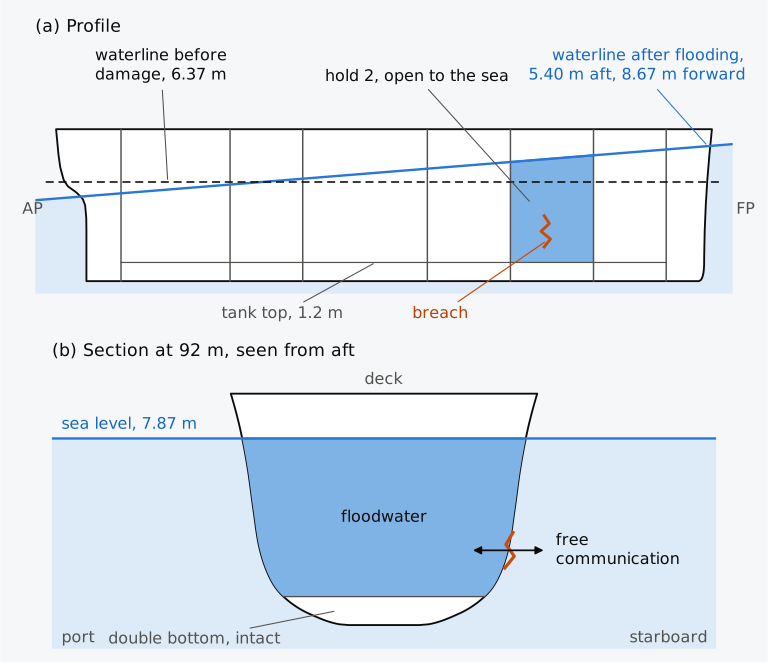
Figure 12.1 Hold 2 of the Series 60 ship open to the sea in the fully loaded departure condition, 7707 t, with a permeability of 0.70: (a) profile, heights three times as large as lengths; (b) the section at 92 m from the AP, seen from aft, at true scale.
12.1.2 Modes of loss
To survive damage, a ship must stay afloat, with enough intact volume to carry its weight, and retain enough stability and clearance at openings to resist the wind and the sea. Its equilibrium may include a list. A flooded ship can be lost in three ways4, which Fig. 12.2 shows on the Series 60 ship. If the intact part of the hull, up to the deck, has less volume than the displacement requires, the ship settles bodily until the sea closes over it, and it founders. If that volume is enough, but no trim brings the centre of buoyancy of the intact part under G before one end goes under, the ship goes down by the head or by the stern and plunges, because its longitudinal stability has failed, as in the Titanic. If no accessible stable heel balances the ship before it overturns, it capsizes; an equilibrium alone does not ensure survival of the flooding transient. A ship left with a negative GM may also come to rest at an angle of loll, as in Sec. 4.9.1, with little of its range of stability left.
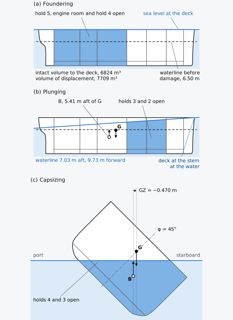
Figure 12.2 Modes of loss of the Series 60 ship: (a) hold 5, the engine room and hold 4 open; (b) holds 3 and 2 open; (c) holds 4 and 3 open, at a light draught. Heights in (a) and (b) three times as large as lengths.
The highest deck that the transverse watertight bulkheads reach is the bulkhead deck. Where the sea rises above it over a flooded compartment, the water can run over the tops of the bulkheads into the compartments beyond. A bulkhead that stops below the new waterline lets the water of a bilged compartment flow on until the vessel sinks, unless a watertight flat joins the tops of the bulkheads and holds the water in9. In the Titanic the water passed over the bulkheads that stopped at E deck. The subdivision rules of the International Convention for the Safety of Life at Sea, 1974 (SOLAS 1974), as first adopted, kept the damaged waterline below a margin line, drawn along the side at least 76 mm below the upper surface of the bulkhead deck10.
Flooding can spread beyond the compartments first opened when the sinkage, trim and heel bring openings in the bulkheads, the shell or the decks under water, and the ship may sink or capsize without ever reaching equilibrium7. In this progressive flooding the openings that matter most are those that cannot be closed weathertight, whose immersion gives the downflooding angle of Chapter 11.
The reserve buoyancy of Sec. 3.7.1, the watertight volume of the hull above the waterline, is the volume into which a flooded ship sinks. The freeboard that remains matters as much as the GM, since a flooded ship with a positive GM but little freeboard immerses its deck edge at a small angle of heel. The range of positive righting levers is then short, and the resistance to wind and waves small7. In Chapter 8, lowering the deck of the intact Series 60 ship by 1 m, from 3.39 m to 2.39 m of freeboard, reduced the largest lever without free surfaces from 0.529 m to 0.289 m, with GM unchanged.
12.2 Permeability
12.2.1 Volume and surface permeability
Cargo, machinery, stores, frames and fittings occupy part of a flooded compartment, and the water can fill only the rest. The volume permeability of a space, μ, is the fraction of its volume that water can occupy6,
where is the moulded volume of the space, or of the part of it below the waterline, and the volume of water that it can hold. The contents also take up part of the free surface of the water, whose area and second moments are then smaller than those of the compartment. The fraction of the surface left to the water is the surface permeability, . Where no better data exist, it is taken equal to the volume permeability6, as in this chapter. Multiplying both area and second moments by this single factor also assumes that the permeable part is distributed uniformly over the compartment; concentrated obstructions need their actual geometry.
A box of 10 m³ that holds a solid block of 2 m³, for example, has room for 8 m³ of water and a permeability of 0.80. When it is flooded, it admits 8 m³ of water and loses 8 m³ of buoyancy, not 10 m³.
For a cargo the permeability follows from its stowage. As in Chapter 11, the stowage factor SF of a cargo is the volume that a tonne of it occupies as stowed, in m³/t, voids between the pieces included. A tonne of the solid material occupies , where is its density in t/m³, and the rest of the stowed volume, , is the broken stowage of that tonne, which water can fill8. Dividing by the stowage factor gives
A dense cargo stowed loosely has a high permeability, and a cargo stowed solidly a low permeability. Coal stowed at 44 cubic feet to the ton (1.23 m³/t), the solid coal weighing 80 lb per cubic foot (1.28 t/m³), leaves about 0.36 of its bunker to the water9.
12.2.2 Permeabilities in the rules
The convention of 1974, as amended (SOLAS), prescribes the permeabilities to be assumed in regulation 7-3 of its chapter II-1. In the consolidated edition of 2024, spaces for stores are taken at 0.60, accommodation at 0.95, machinery spaces at 0.85 and void spaces at 0.95, and spaces intended for liquids at 0 or 0.95, whichever gives the more severe requirement11. In effect, a tank is assumed either full, admitting no water, or empty, admitting as much as a void. A full side tank that extends well above the waterline loses its contents on one side when it is holed, and the effect on stability can then be worse than that of sea water entering the tank if it were empty7.
The permeability of cargo spaces changes with the draught at which the damage is assumed, since a full hold admits little water and a ship at a light draught usually carries little cargo. SOLAS uses three draughts. The deepest subdivision draught is the summer load line draught, and the light service draught corresponds to the lightest loading expected in service, with the ballast needed for stability and immersion. The partial subdivision draught lies 60 % of the way from the light service draught to the deepest11. Dry cargo spaces, container spaces and spaces for liquid cargo are taken at 0.70 at the deepest subdivision draught, 0.80 at the partial subdivision draught and 0.95 at the light service draught, and ro-ro spaces at 0.90, 0.90 and 0.95 at the three draughts11; other values may be used if they are substantiated by calculation11. Unless another value is stated, this chapter takes the holds of the Series 60 ship at 0.70, the value for dry cargo spaces at the deepest subdivision draught, with the engine room at 0.85 and the peaks at 0.95.
Example 12.1. The permeability of a cargo. A hold is loaded with a bagged cargo that stows at 1.60 m³/t, and the solid material of the cargo has a density of 1.40 t/m³. The hold is opened to the sea, with 1500 m³ of its moulded volume below the waterline. Find the permeability of the cargo and the volume and mass of the sea water that the hold admits below the waterline.
12.3 Lost buoyancy and added weight
12.3.1 The two methods
With the permeability known, the floating position of a flooded ship can be found in two ways. In the method of lost buoyancy, also called the method of constant displacement, the water-filled fraction of the flooded compartment is taken as no longer part of the buoyant hull6. Its permeable volume below the waterline is lost to the sea, while the weight of the ship and its centre of gravity G are unchanged, provided no cargo, stores or liquids are lost or shifted. The ship sinks and trims until the rest of the hull regains the lost buoyancy, and the hydrostatics are those of the hull less the compartment. In the method of added weight, the water that enters is a load added to the ship. The displacement and G change, the hydrostatics are those of the intact hull, and the free surface of the water in the compartment must be allowed for6. The amount of water that enters depends on the final waterline, which is not known at the start, and this method is applied in successive passes until the water and the waterline agree4.
Both methods, which Fig. 12.3 shows on a box barge, describe a single physical state and must give a single final waterline. Their displacements and metacentric heights differ, but their righting moments are equal6.
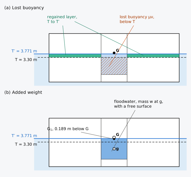
Figure 12.3 The two methods on a box barge 70 m × 13 m × 6.5 m at 3.30 m, with a compartment from 28 m to 42 m open to the sea, permeability 0.85: (a) lost buoyancy, Δ and G unchanged; (b) added weight, G moved to . Heights four times as large as lengths.
12.3.2 Parallel sinkage
Consider a compartment whose lost-volume and waterplane centroids lie on the vertical through the centre of flotation F, with no transverse asymmetry, and let be the moulded volume of the compartment below the waterline, the area of the waterplane within it, and the area of the whole waterplane. By lost buoyancy the volume μ is lost, and the ship sinks by δ without trimming, gaining a layer over the waterplane that remains intact. Within the compartment the layer is open to the sea too, and only the intact waterplane counts; the permeability of so thin a layer at the waterline is that of the surface, . Setting the gain equal to the loss, with the sides vertical over δ, gives
The waterplane that remains has its centroid at F′, the centre of the intact waterplane. For a compartment symmetric about the centreline and about F, F′ coincides with F and the ship sinks parallel. Where the sides are not vertical over δ, a second approximation takes the intact waterplane at half the sinkage, or the mean of the intact waterplanes at the two waterlines4,7. Where the top of the compartment lies below the waterline, for example under a watertight flat, the waterplane loses nothing (), and the ship sinks by μ as if a mass equal to the lost buoyancy had been loaded over F8.
12.3.3 Metacentric height by lost buoyancy
By lost buoyancy, and KG are those of the intact ship, and the centre of buoyancy rises to the height KB′ above the keel, the centroid of the hull below the new waterline less μ times the compartment below it. The layer of the compartment between the two waterlines, which Eq. (12.3) counted at , is here taken at μ; the two agree because this chapter takes equal to μ. The metacentric radius is that of the intact waterplane,
where is the volume of displacement of the intact ship and the transverse second moment of the intact waterplane about the longitudinal axis through its centroid F′. For a compartment that spans the breadth, is the second moment of the whole waterplane less times that of the part within the compartment. In this method the floodwater has no free surface, because it does not belong to the ship.
12.3.4 Metacentric height by added weight
By added weight, the water admitted has the volume μ, where is the volume of the compartment below the final waterline, and the mass , with its centroid at the height above the keel. The displacement and the height of G become
The intact hull floats at with its own and . The water has a free surface over the compartment, and its second moment, reduced by the surface permeability, lowers GM as the free surface of a slack tank does in Sec. 5.3.1,
where and is the second moment of the waterplane of the compartment. For a compartment symmetric about the centreline, is taken about the centreline, which is then its own centroidal axis and the axis through F′ as well. Equation (12.6) in this form therefore holds for symmetric flooding; for an unsymmetrical compartment both second moments, of the whole waterplane in and of the compartment in , must be taken about the axis through F′, as Sec. 12.5.2 shows.
12.3.5 Equality of the righting moments
In both methods the forces on the ship are identical, and the methods differ only in which forces are counted as weight and which as buoyancy. Consider the damaged ship at its final waterline, heeled through a small angle δφ about the axis through F′. By lost buoyancy, the righting moment is that of a hull with the waterplane and the displacement ,
and by added weight it is that of the intact hull at , less the effect of the free surface of the floodwater,
where and are the second moments of the whole waterplane and of the compartment’s waterplane about the axis through F′. The two brackets are equal term by term. The water fills the volume μ that the lost-buoyancy hull leaves out, with an identical centroid, which gives , and the waterplanes satisfy . Hence
with . The metacentric heights stand in the inverse ratio of the displacements7. The argument holds at any angle of heel, since at every angle the two methods describe the ship by identical forces and give a single curve of righting moments.
The equality holds only when the free surface of the floodwater is taken about the axis through F′, about which the damaged ship inclines; the surface inside remains part of the surface of the sea. For a compartment symmetric about the centreline that axis is the centreline. A compartment filled completely below the waterline has no free surface, and its water acts as a loaded mass.
12.3.6 The displacement in damage calculations
The two methods give different metacentric heights, and a damaged GM has no meaning until the method is stated6. A criterion of residual GM, such as the 0.05 m of the older rules, is meant on the lost-buoyancy basis and corresponds by added weight to 0.05 m multiplied by , the ratio of the two displacements7. Under the present rules, SOLAS requires the curve of righting levers of a damaged ship to be determined, at every stage of flooding, with the displacement of the intact loading condition and with the ship trimming freely11. Once the water inside has reached the level of the sea, this is the method of lost buoyancy, the method of the stability programs6. In this chapter, too, GM, and GZ of a damaged ship are those of lost buoyancy at the intact displacement, unless the added weight is named.
Example 12.2. A central compartment by both methods. A box barge 70 m long, 13 m wide and 6.5 m deep floats in sea water at a draught of 3.30 m, with KG = 3.90 m and G at mid-length on the centreline. A compartment between transverse bulkheads 28 m and 42 m from the after end, extending across the barge from a double bottom 1.0 m high to the deck, is opened to the sea. Its permeability, for volume and for surface, is 0.85. Find the new draught and the metacentric height by lost buoyancy and by added weight, and compare the righting moments.
As can be seen from Table 12.1, the displacement, KG, KB, BM and GM of the flooded barge depend on the method, but the draught and the righting moment do not.
Table 12.1 The barge of Example 12.2, intact and by the two methods. Heights above the keel, and the righting moment per radian of heel.
| Quantity | Intact | Lost buoyancy | Added weight |
|---|---|---|---|
| Displacement (t) | 3078.1 | 3078.1 | 3517.5 |
| Draught (m) | 3.300 | 3.771 | 3.771 |
| KG (m) | 3.900 | 3.900 | 3.711 |
| KB (m) | 1.650 | 1.814 | 1.886 |
| BM (m) | 4.268 | 3.542 | 3.735 |
| Free surface correction (m) | – | – | 0.635 |
| GM (m) | 2.018 | 1.456 | 1.274 |
| (kN·m) | 60927 | 43975 | 43975 |
The moments follow the rounded intermediate values in Example 12.2, before the additional rounding of the entries in this table.
12.4 Sinkage and trim
12.4.1 Trim about the centre of the intact waterplane
So far the compartment has been centred on F in a symmetric box, so its flooding causes no trim. A compartment whose lost-volume centroid lies away from the centre of the remaining waterplane also trims the ship. By lost buoyancy the ship may be imagined first held against trimming, sinking parallel by δ of Eq. (12.3). The layer gained over the intact waterplane has its centroid at F′, but the buoyancy μ is lost at the centroid of the compartment, forward of the AP. The centre of buoyancy therefore moves forward or aft by μ, and G does not move. The ship trims until B lies again under G4,7, turning about the transverse axis through F′, which lies at
where is the centre of flotation of the intact ship and the centroid of the compartment’s waterplane, both measured forward of the AP. The moment to change trim one centimetre is that of the intact waterplane about F′, whose longitudinal second moment follows from the parallel-axis theorem,
where is the second moment of the whole waterplane about the transverse axis through F and that of the compartment’s waterplane about its own centroid. With , in t·m/cm, the trim is
positive by the stern when the compartment lies aft of F′, as in Eq. (6.7) for a mass. The waterline turns about F′, and the draughts at the perpendiculars become
The method is linear in that it takes the sides as vertical over the sinkage and the trim and keeps the intact waterplane, its centre and its MCT unchanged while the ship trims. When the trim is large, MCT′ may be taken as the mean of its values at the two waterlines9. For a box, whose sides are vertical, the floating position can be found exactly, and the trim angle θ, positive bow up, satisfies the wall-sided relation of Sec. 4.7.2 written for trim,
where is the centre of buoyancy of the flooded box at the draught on even keel, and . The trim is then , and the draughts follow from Eq. (12.11).
Example 12.3. A compartment forward of mid-length. A box barge 80 m long, 14 m wide and 7 m deep floats in sea water at 3.50 m on even keel, with KG = 4.20 m and G at mid-length. A compartment between transverse bulkheads 56 m and 70 m forward of the after end, extending across the barge from a double bottom 1.2 m high to the deck, is opened to the sea. Its permeability, for volume and for surface, is 0.70. Find the draughts at the ends by the linear method of lost buoyancy, and compare them with the exact floating position.
12.4.2 Flooding calculator (Calculator 12.1)
With Calculator 12.1 you can flood a compartment of a box barge by both methods. You choose the barge, its draught and KG, and a compartment between two transverse bulkheads anywhere along it, from the bottom or a double bottom up to the deck, with its permeability. You obtain the sinkage, the centre of the intact waterplane, the trim and the draughts, GM by lost buoyancy and by added weight, and the righting moment by each method, with G at mid-length on the centreline. Because the sides are vertical, the answers are exact while the deck edge stays out of the water, the bottom stays in it and the floodwater stays above the floor of the compartment. A note appears when any of these conditions fails or when the barge cannot float at all.
12.4.3 End holds of the Series 60 ship
The waterplane of a ship, unlike that of a box, changes as the ship sinks and trims, most of all at the ends, and the linear method then loses accuracy. Table 12.2 compares it with the floating position computed on the hull for the holds at the two ends of the cargo space of the Series 60 ship. In the fully loaded departure condition the ship floats at 6.367 m on even keel. At that draught Table 6.1, interpolated linearly between 6.2 m and 6.4 m, gives TPC = 14.30 t/cm, = 56.43 m and MCT 1 cm = 86.88 t·m/cm, and hence = 100 × 14.30/1.025 = 1395.1 m² and = 100 × 121.92 × 86.88/1.025 = 1033406 m⁴. The volume, waterplane and centroids of each hold below that waterline and above the tank top at 1.2 m come from the Series 60 surface of Chapter 1, and the permeability is 0.70.
Table 12.2 End holds of the Series 60 ship open to the sea in the fully loaded departure condition, at 6.367 m on even keel, with a permeability of 0.70: the data of each hold below that waterline and above the tank top at 1.2 m, the linear method with the waterplane of Table 6.1, and the floating position computed on the hull. Hold 1 extends from 100 to 114 m, hold 2 from 84 to 100 m and hold 5 from 9 to 30 m; trim positive by the stern.
| Quantity | Hold 1 | Hold 2 | Hold 5 |
|---|---|---|---|
| Volume below the waterline, (m³) | 316.54 | 860.63 | 878.83 |
| Centroid of that volume, (m) | 105.604 | 91.192 | 21.575 |
| Waterplane area of the hold, (m²) | 68.63 | 180.35 | 244.52 |
| Centroid of that area, (m) | 105.598 | 91.279 | 20.792 |
| Second moment of that area about its centroid, (m⁴) | 1002.5 | 3715.0 | 8310.1 |
| Centre of the intact waterplane, (m) | 54.68 | 52.96 | 61.41 |
| MCT′ of the intact waterplane (t·m/cm) | 76.71 | 72.49 | 65.56 |
| Trim by the linear method, (m) | −1.508 | −3.257 | 3.832 |
| by the linear method (m) | 5.855 | 5.427 | 8.800 |
| by the linear method (m) | 7.363 | 8.684 | 4.968 |
| Trim computed on the hull, (m) | −1.550 | −3.270 | 3.396 |
| computed on the hull (m) | 5.832 | 5.398 | 8.529 |
| computed on the hull (m) | 7.381 | 8.668 | 5.133 |
For holds 1 and 2 the linear method gives the trim within 3 % and the draughts within 3 cm. For hold 5 it overstates the trim by 0.44 m, or 13 %, because the overhang of the stern enters the water as the stern sinks. The waterplane grows aft, and the buoyancy gained and the MCT rise faster than the linear method allows. For trims of this size the floating position is found on the hull itself, by balancing the displacement and the longitudinal moment of the flooded hull at trial waterlines, as in Sec. 7.7.1 for an intact ship.
12.5 Unsymmetrical flooding
12.5.1 List from a wing compartment
The compartments so far have spanned the breadth of the ship. A compartment on one side of a longitudinal bulkhead, a wing compartment, also heels the ship, and by lost buoyancy the reasoning follows that for trim. With the transverse centroid of the compartment, positive to port, the lost volume μ below the new waterline shifts the centre of buoyancy away from the damaged side by
and the ship heels towards the damage until B lies again under G. A starboard compartment has , moves B to port and heels the ship to starboard, a positive heel φ in the convention of Chapter 1. For small angles, , with from Eq. (12.4). The ship turns about the longitudinal axis through F′, which lies off the centreline at , on the side away from the damage. in Eq. (12.4) is taken about that axis8. For a box the heel can again be found exactly, from the wall-sided relation of Sec. 4.7.2,
Example 12.4. A wing compartment. The box barge of Example 12.2, 70 m × 13 m × 6.5 m, floats at 3.30 m with KG = 3.90 m and G on the centreline. A longitudinal bulkhead 3 m from the starboard side runs between transverse bulkheads 28 m and 42 m from the after end, and the wing compartment it forms, above a double bottom 1.0 m high, is opened to the sea. Its permeability, for volume and for surface, is 0.85. Find GM by lost buoyancy and the angle of list.
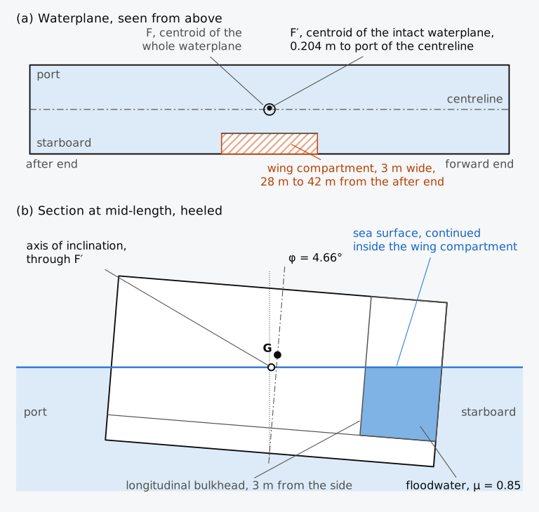
Figure 12.4 The wing compartment of Example 12.4: (a) the waterplane, seen from above; (b) the section at mid-length, seen from aft, at the equilibrium heel.
12.5.2 The free surface of a wing compartment
The water in a wing compartment open to the sea keeps its surface at sea level as the ship heels, running in as the damaged side goes down and out as it rises. Its surface inclines with the sea about the axis through F′, and not about its own centroid. By added weight, the free surface correction of Eq. (12.6) must then use the second moment of the compartment’s waterplane about the axis through F′, and the whole waterplane must be taken about that axis too. Upright, the barge of Example 12.4 with its water displaces = 3003 + 85.46 = 3088.46 m³, with = 3.853 m, = 1.697 m and = 12815.8/3088.46 = 4.150 m. The slack-tank formula of Chapter 5, with the compartment’s own second moment, 0.85 × 31.5 = 26.8 m⁴, gives = 1.985 m. The correct value, from Eq. (12.7), is 3003 × 1.7321/3088.46 = 1.684 m, and the slack-tank formula overstates the stability by 0.30 m, or 18 %. Taking the second moment about the centreline instead gives 1.696 m, still 0.012 m too high. The method of lost buoyancy needs no such correction, because its waterplane already turns about F′. Care is also needed with a pair of wing tanks connected across the ship, whose surfaces act together about the centreline and multiply the free surface effect7.
12.5.3 Counterflooding and cross-flooding
A wing tank flooded by itself can heel the ship further than a larger damage that also opens the compartment inboard of it, since the inboard compartment adds a loss of buoyancy on both sides of the centreline and so reduces the heel7. For this reason, the deterministic rules of SOLAS 1974 asked for a damage of lesser extent wherever it gave a worse heel or a greater loss of metacentric height10. Under the present rules every case of flooding that involves a wing compartment is counted, and the wing compartment together with the space inboard of it may be added as a separate case11.
A list can be reduced by flooding a compartment on the other side, which is called counterflooding. Counterflooding also reduces the freeboard and may introduce free surfaces4. Whether it improves the situation depends on the complete flooding sequence and remaining stability; counterflooding must follow the ship’s approved damage-control arrangements. Spaces on the two sides may instead be joined by ducts or pipes, through which the water entering the damaged side flows across. In this cross-flooding, unless the openings are large, the damaged side fills first and the ship heels before the water equalizes7. Solda estimated the time needed to equalize through a duct of area as
where is the volume of water to be transferred, the head at the start and a flow coefficient of about 0.65 for a short, direct connection7. SOLAS requires unsymmetrical flooding to be kept as small as an efficient arrangement allows, the means of correcting a large heel to be self-acting where practicable, and the controls of equalization devices to be operable from above the bulkhead deck of a passenger ship or the freeboard deck of a cargo ship11. Where cross-flooding devices are fitted, equalization must take no more than 10 minutes11.
12.6 Stability after damage
12.6.1 The curve of righting levers after damage
So far the damaged ship has been judged by its metacentric height, which describes only the start of the curve of righting levers. A flooded ship has lost freeboard, often trims and may list, and its levers at larger angles must be computed. By lost buoyancy the calculation is that of Sec. 8.1.5 for the intact ship with the trim free, applied to the hull less μ times each flooded compartment. At each angle of heel the waterline is moved and turned until the volume of the hull below it, less the floodwater, equals the intact volume of displacement, with its centroid B in the transverse plane through G. The lever is then the horizontal distance from G to the vertical through B. The water in the flooded compartments follows the sea surface at every angle, and computer programs have long calculated the curves of damaged ships in this way7. The free surfaces of the intact tanks are allowed for as in Chapter 11, by a virtual rise of G at every angle.
12.6.2 Damage cases of the Series 60 ship
The Series 60 ship is now taken in the fully loaded departure condition, 7707 t with KG = 5.887 m and free surface moments of 1573.5 t·m, with each of its compartments in turn open to the sea. The floating positions and metacentric heights are listed in Table 12.3 and the features of the curves of righting levers in Table 12.4. Four of the curves are plotted in Fig. 12.5. The holds and the engine room are flooded above an intact double bottom, at permeabilities of 0.70 and 0.85, and the peaks from the keel to the deck, at 0.95. Two damages that open two adjacent compartments are added: hold 1 with the fore peak, as after a collision that breaches the collision bulkhead at 114 m, and the engine room with hold 4. The fresh water in the aft peak, 110 t with a free surface moment of 328.7 t·m, is lost when the peak is opened. The freeboard is the least height of the deck at side above the water, found at the stem or the stern of a trimmed ship.
Table 12.3 Floating position and metacentric height of the Series 60 ship in the fully loaded departure condition with compartments open to the sea, by lost buoyancy with the trim free, at the intact displacement mass, 7707 t, or 7597 t with the aft peak open and its fresh water lost. Draughts at the perpendiculars, and , the least freeboard and GM corrected for free surfaces, all in metres.
| Damage | ||||
|---|---|---|---|---|
| Intact | 6.37 | 6.37 | 3.386 | 0.456 |
| Aft peak | 6.20 | 6.49 | 3.260 | 0.498 |
| Hold 5 | 8.53 | 5.13 | 1.127 | 0.544 |
| Engine room | 8.11 | 5.93 | 1.577 | 0.510 |
| Hold 4 | 7.54 | 7.60 | 2.149 | 0.481 |
| Hold 3 | 6.01 | 8.40 | 1.335 | 0.417 |
| Hold 2 | 5.40 | 8.67 | 1.061 | 0.493 |
| Hold 1 | 5.83 | 7.38 | 2.361 | 0.496 |
| Fore peak | 6.26 | 6.56 | 3.191 | 0.465 |
| Hold 1 and the fore peak | 5.67 | 7.66 | 2.078 | 0.509 |
| Engine room and hold 4 | 9.62 | 7.48 | 0.067 | 0.779 |
Table 12.4 Curves of righting levers of the cases of Table 12.3, corrected for free surfaces: the largest lever, the angle of heel at which it occurs, and the range of positive levers from upright, “> 60” where the lever is still positive at 60°.
| Damage | At φ | Range | |
|---|---|---|---|
| Intact | 0.409 | 35.2 | > 60 |
| Aft peak | 0.440 | 35.3 | > 60 |
| Hold 5 | 0.273 | 27.8 | 51.7 |
| Engine room | 0.252 | 26.5 | 50.4 |
| Hold 4 | 0.189 | 21.4 | 40.6 |
| Hold 3 | 0.231 | 27.4 | 50.0 |
| Hold 2 | 0.290 | 30.0 | 54.3 |
| Hold 1 | 0.384 | 33.4 | 59.4 |
| Fore peak | 0.410 | 35.1 | > 60 |
| Hold 1 and the fore peak | 0.377 | 32.8 | 58.4 |
| Engine room and hold 4 | 0.080 | 9.8 | 20.2 |
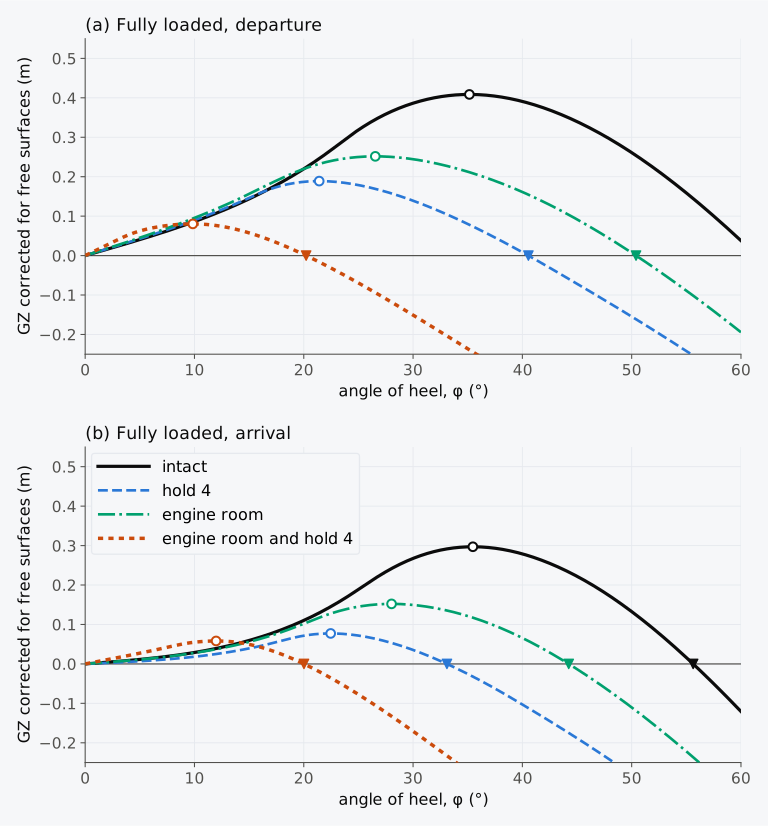
Figure 12.5 Curves of righting levers of the Series 60 ship, intact and with compartments open to the sea, corrected for free surfaces: (a) fully loaded departure; (b) fully loaded arrival. Circles mark the largest levers, and triangles the angles at which the levers vanish.
The ship remains afloat in all the cases of Table 12.3, and with a single compartment open its stays near the intact value; it rises in seven of the eight cases, hold 3 being the exception. A hold above an intact double bottom takes away only 0.70 of the waterplane over it. The sinkage raises KB, and the rest of the waterplane widens as the flared hull sinks and trims7; in Table 11.6 the intact KM of this hull rises from 6.523 m at 7500 t to 6.581 m at 8000 t. With the aft peak open, 0.040 m of the rise of 0.042 m comes instead from the free surface of the fresh water lost with the peak, and the virtual rise of G falls from 0.204 m to 0.164 m.
In Table 12.4, however, the largest lever falls wherever the ship sinks deeply, from 0.409 m to 0.189 m with hold 4, and the curve reaches its maximum earlier, because the deck edge meets the water at a smaller angle. With the engine room and hold 4 both open, over 38 m of the length, the ship sinks until its deck at the stern is only 0.067 m above the water and the margin line, 76 mm below the deck, is 9 mm under water. , 0.779 m, is then larger than intact, yet the largest lever is 0.080 m at 9.8°, and the levers vanish at 20.2°. This indicates that a flooded ship can float upright with a large GM and still have almost no stability; the freeboard then governs the levers.
The useful range is shortened further by openings that cannot be closed weathertight, such as the ventilator to the engine room of Chapter 11, which stands 2.0 m above the deck, 40 m forward of the AP and 6.0 m to starboard of the centreline. The intact ship in the departure condition, heeled to starboard towards the ventilator, immerses it at 42.6°. With hold 4 open the ventilator is 4.19 m above the water when the ship floats upright, but it reaches the water at 34.0°, before the levers vanish at 40.6°. Water entering there floods the engine room, and the ship is left with the engine room and hold 4 open, whose levers vanish at 20.2°.
In the fully loaded arrival condition of Chapter 11, 7236 t with KG = 6.129 m, the intact is only 0.118 m. Seven of the ten damage cases leave a larger , but three leave less: 0.117 m with the engine room open, 0.068 m with hold 4 and 0.047 m with hold 3. With hold 4 the largest lever is 0.077 m at 22.5°, and the engine room and hold 4 together leave a largest lever of 0.058 m at 12.0° and a range of 20.0°. The arrival condition already fails the intact criteria of Chapter 11, and a flooded hold leaves it with still less stability.
The freeboard left after damage also depends on the permeability. With hold 4 at 0.60, the value that the convention of 1974 gave for cargo spaces10, instead of 0.70, the ship sinks to 7.36 m aft and 7.39 m forward and keeps 2.364 m of freeboard. At 0.95, the value for an empty hold, the draughts become 8.05 m aft and 8.21 m forward and the freeboard 1.545 m.
12.6.3 Intermediate stages of flooding
The water inside has so far stood at the level of the sea. This is the final stage of flooding, and it is not always the worst. If the breach is small, or the water reaches a space through a non-watertight boundary or a cross-flooding duct, the space fills over minutes or hours. Until it is full, in the intermediate stages of flooding, the water inside lies below the sea level and keeps its volume as the ship heels, like a liquid in a slack tank. The method of added weight then applies, with the free surface of the water that has entered7. In the early stages the water spreads across the floor of the space while little of it has entered, and its free surface may outweigh the small gain from the sinkage. A ship flooded symmetrically may even take a list from a negative GM, and the GM needed is generally greatest when the water just covers the double bottom7.
The explanatory notes that IMO issued with the present SOLAS rules, Resolution MSC.429(98)/Rev.2, treat the two stages in this way. A space opened directly by the damage is taken as flooded at once, and intermediate stages are calculated where the water spreads through non-watertight boundaries or cross-flooding and takes more than 60 s to equalize. In each intermediate phase of a stage the floodwater is a constant volume with a single free surface, and the righting levers are calculated with the intact displacement. In the full phase of each stage the water reaches the sea level, and the method of lost buoyancy is used12.
Hold 4 of the Series 60 ship, 24 m long over the flat middle of the hull, has a wide tank top. In the departure condition, when 43 m³ of water covers it 0.17 m deep, referred to the intact displacement falls from 0.456 m to −0.19 m, so the upright state becomes unstable. A list can develop if a stable inclined state is reached before downflooding or capsize. As can be seen from Fig. 12.6, becomes positive again only when the water has risen to 2.89 m above the baseline, a quarter of the way to its final volume, and ends at 0.481 m when the hold is full to the sea level. For hold 2, in the narrower forebody, falls only to 0.372 m when the water first covers the tank top. The rule calculation takes a hold opened directly by the damage as flooded at once12, but that does not make the physical transient harmless. A hold that floods through a small opening or pipe passes through these stages. For a cargo ship without cross-flooding devices, SOLAS asks the Administration to require further investigation where it considers that the stability in intermediate stages of flooding may be insufficient11. Animation 12.1 follows hold 2, whose filling shows in profile as a trim; hold 4 would take a list, which a profile cannot show.
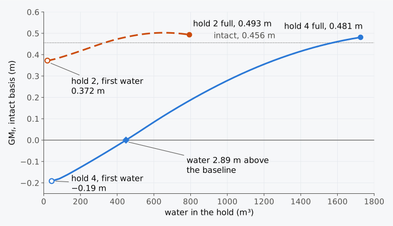
Figure 12.6 of the Series 60 ship, referred to the intact displacement, against the water in hold 4 and in hold 2 as each fills in the fully loaded departure condition.
Animation 12.1 Hold 2 of the Series 60 ship filling through a small breach in the fully loaded departure condition, 7707 t, in 40 equal steps of its final volume. is referred to the intact displacement. No sound; 12 s.
12.7 Floodable length and subdivision
Watertight bulkheads limit how much of a ship a single damage can open. They also add to the cost of building and running a ship, and bulkheads set close together break up the holds and hinder the work of the ship. A ship divided so finely that it could hardly sink might be of no commercial use4,7. More bulkheads make it more likely, too, that a damage falls on a bulkhead and opens two compartments at once7. The degree of subdivision is a compromise between these demands, and the rules of subdivision set its least acceptable level.
12.7.1 The floodable length
For most of the twentieth century the subdivision of passenger ships was judged by the length of ship that could be flooded. The ship was taken as lost when the damaged waterline reached the margin line, 76 mm or more below the bulkhead deck at side4. In SOLAS 1974 as first adopted, the floodable length at a point of the length is the greatest part of the length, with its centre at that point, that can be flooded under the stated permeabilities without submerging the margin line10, and the volume of a space is counted only up to the margin line10. Part B of its chapter II-1 applied to passenger ships only10. For the Series 60 cargo ship the floodable length illustrates the method and is not a requirement.
By hand, the curve was found from a set of waterlines, each touching the margin line. Each waterline fixed the volume and the centroid of the buoyancy that must be lost, and these were converted by trial into a length centred at a point4. For the Series 60 ship the floodable length was computed directly by lost buoyancy, with the ship upright and free to trim. For each position of its centre, a compartment from the baseline to the margin line was lengthened until the margin line just reached the water. Near the ends of the ship the length is limited by the terminals of the curve, which lie at the extremities of the margin line7. A compartment centred at a distance from a terminal can be at most long, and the curve there follows straight lines at tan⁻¹ 2 to the base when both scales are equal4.
12.7.2 The floodable length of the Series 60 ship
Figure 12.7 shows the floodable length of the Series 60 ship for three uniform permeabilities, 0.60, 0.85 and 0.95, at its summer draught, 6.502 m on even keel. At that draught the ship displaces 7901.8 t with KG = 5.887 m, and its margin line lies 76 mm below the flat deck, at 9.678 m. The floodable length is greatest at 55 m from the AP, near the middle of the ship, where the hull is fullest and a flooded length centred near F sinks the ship with little trim. There the curves reach 52.7 m, 36.5 m and 32.6 m. It is least at 87 m, in the forebody, where the curves fall to 21.1 m, 14.6 m and 13.0 m. The sections there are still full, but they lie far forward of F, and the trim by the head brings the margin line at the stem down quickly. Nearer the ends the sections fine away and a metre of length holds less buoyancy, so the curve rises again until the terminal lines cut it, with a second, shallower minimum aft, at 27 m.
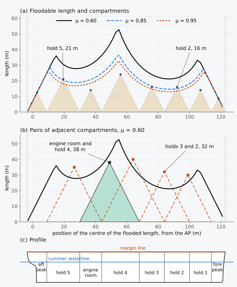
Figure 12.7 Floodable length of the Series 60 ship at its summer draught, 6.502 m: (a) the curves for three permeabilities, with the compartments drawn as triangles; (b) the pairs of adjacent compartments between the peaks against the curve for 0.60, dashed where their apexes lie above it; (c) profile, heights twice as large as lengths.
Each compartment is drawn on the curves as an isosceles triangle, with the compartment as its base and its apex at a height equal to its length. With equal scales its sides are the lines at tan⁻¹ 2 that bound a compartment centred at the apex6. A compartment lies within the floodable length if its apex lies below the curve. With a uniform permeability of 0.60 every compartment of the ship lies within it, and hold 4, 24 m long, uses only 48 % of the 50.0 m available at its centre. At 0.85 the apexes of hold 5 and hold 2 lie above the curve: hold 5 is 21 m long where 20.3 m may flood, and hold 2 is 16 m long where 15.0 m may flood. At 0.95 hold 3 joins them, 16 m against 14.8 m. Hold 2 lies near the low point of the curve, and there is little room for long holds in the forebody of a full cargo ship.
12.7.3 Factor of subdivision and permissible length
The factor of subdivision goes back to the convention of 1914, whose regulations tabulated it against the length of the ship5. Under SOLAS 1974 as adopted, the permissible length of a compartment is its floodable length multiplied by the factor of subdivision , which decreases regularly and continuously as the length of the ship increases, and as its service changes from mainly carrying cargo to mainly carrying passengers10. A ship’s position between these two services is set by a criterion numeral, formed from the volumes of the machinery space, of the passenger spaces and of the whole ship below the margin line, and from the number of passengers10.
With a factor near 1 the geometric standard addresses any single compartment, and with a factor of 0.50 or less any two adjacent compartments; the compartment standard is roughly the inverse of the factor4. A ship whose every compartment lies within the floodable length meets that geometric one-compartment standard; residual stability and openings still need separate checks. Where the factor was 0.50 or less, the combined length of any two adjacent compartments was not to exceed the floodable length at their common centre10, and the ship was a two-compartment ship. Each pair is drawn as a triangle on its combined length, and its apex must lie below the curve. Two bulkheads closer together than 3.05 m plus 3 % of the length, or 10.67 m if less, counted as a single bulkhead10. For the Series 60 ship at 0.60, only the pair of the engine room and hold 4, 38 m against 43.1 m, lies within the curve in Fig. 12.7(b), and holds 3 and 2, 32 m long where 21.3 m may flood, exceed it most. The Series 60 ship is therefore a one-compartment ship.
Example 12.5. Floodable length of a box. The box barge of Example 12.2, 70 m × 13 m × 6.5 m, floats at 3.30 m in sea water with KG = 3.90 m and G at mid-length. Its margin line is 76 mm below the deck. Find the floodable length at mid-length for a compartment across the barge from the bottom to the deck, with a permeability of 0.85, and the permissible length there for a factor of subdivision of 0.50.
In Explorer 12.1 you can choose the permeability of the Series 60 ship, 0.60, 0.85 or 0.95, a factor of subdivision between 0.30 and 1.00, and whether the single compartments or the pairs of adjacent compartments are shown. The graph shows the floodable length, the permissible length given by the factor and the compartments or pairs as triangles, and every triangle whose apex lies above the permissible length is marked. A table lists each compartment or pair with its length, the floodable length at its centre and their ratio, which is the smallest factor of subdivision that admits it. The curves come from the hull every 2 m and are interpolated linearly between those points.
We can now return to the Titanic, which had been built as a two-compartment ship, to float with any two adjoining compartments flooded. The damage from the iceberg extended over a length of about 300 ft (91 m), about 10 ft (3.0 m) above the keel, and opened six compartments, from the forepeak to No. 5 boiler room1. With the four forward compartments flooded, the water would not have reached the compartments abaft them1. In the terms of Sec. 12.7.1, these four compartments lay within the length that could be flooded before the sea reached the tops of the bulkheads, but the five forward compartments did not. Once the bow had sunk until the water overflowed E deck, at which seven of the bulkheads stopped, the flooding was progressive, and the ship was lost by plunging2,4. The Wreck Commissioner was advised that the ship would have remained afloat with the six damaged compartments flooded if its bulkhead deck had been watertight, closing the tops of the bulkheads as a watertight flat does, or if the bulkhead abaft No. 5 boiler room had been carried up to C deck1. Divided by longitudinal as well as transverse bulkheads, it would have floated with a list, which water ballast put into suitable places could have corrected, as counterflooding does1.
12.8 Damage stability requirements
12.8.1 Deterministic standards
A deterministic standard prescribes a damage, its position, its extent and the permeabilities, and states what the ship must still achieve after it. The floodable length took no account of the stability of the flooded ship, and from 1948 the conventions added stability requirements for the damage that the factor of subdivision implied4,7. In SOLAS 1974, a damage 3.05 m plus 3 % of the length long, or 10.67 m if less, extending one fifth of the breadth inboard and from the baseline upwards without limit, was to leave a GM of at least 50 mm by lost buoyancy after symmetrical flooding, a heel of not more than 7° after unsymmetrical flooding, and the margin line clear of the water at the final stage10.
These deterministic rules required the prescribed damage to be considered at each relevant position, without assigning probability weights to the positions. The extent was fixed in advance, with lesser extents checked when more severe. Statistics of past collisions later allowed the probability of damage at each position and of each extent to be estimated4. A floodable length curve still shows where bulkheads are best placed; the probabilistic method does not show this, because it evaluates an arrangement already proposed4.
SOLAS now applies its probabilistic rules to cargo ships of 80 m in length and over, but a ship may be excluded from them if it is shown to comply with the subdivision and damage stability requirements of another instrument11. For oil tankers this instrument is Annex I of the International Convention for the Prevention of Pollution from Ships (MARPOL), for chemical tankers the International Code for the Construction and Equipment of Ships Carrying Dangerous Chemicals in Bulk (IBC Code), and for gas carriers the International Code for the Construction and Equipment of Ships Carrying Liquefied Gases in Bulk (IGC Code). The damage stability requirements of the International Convention on Load Lines, 1966, as modified by its Protocol of 1988 (the Load Line Convention), also qualify, except for ships that carry deck cargo11.
Regulation 27 of the Load Line Convention allows a ship to take a smaller freeboard if it can survive flooding. A Type A ship over 150 m in length, designed to carry only liquid cargoes in bulk and assigned a freeboard less than that of a Type B ship, must withstand the flooding of any compartment, with a permeability of 0.85 in the machinery space and of 0.95 elsewhere13. So must a Type B ship over 100 m in length with a reduced freeboard, with the machinery space at 0.85 in a ship over 150 m long13. The freeboard of such a Type B ship may then be reduced by up to 60 % of the difference between the tables for Types A and B, and such a ship is commonly called a Type B-60 ship13. The whole difference may be taken, for the ship commonly called Type B-100, if two adjacent compartments survive flooding together, except at the bulkheads bounding the machinery space13. The ship is taken at its summer load waterline on even keel13, and the damage extends from the baseline upwards without limit and inboard by B/5 or 11.5 m, whichever is less, measured at the summer load waterline13. After flooding, the final waterline must lie below every opening through which progressive flooding can take place, including air pipes, ventilators and openings closed by weathertight doors or hatch covers13. The heel must not exceed 15°, or 17° if no part of the deck is immersed, and the GM in the flooded condition must be positive13. Where the deck outside the flooded compartment is immersed, or the margin of stability is doubtful, the residual curve should have a range of 20° beyond the equilibrium, with a largest lever of at least 0.1 m and an area of at least 0.0175 m·rad within it13.
12.8.2 The probabilistic method
In the present rules for cargo ships and passenger ships, a prescribed damage is replaced by the probability that the ship survives a collision. A ship is taken to be damaged at a random position and over a random length, both drawn from the statistics of past collisions, and the attained subdivision index is a comparative measure of survival under the rule assumptions. It is not an exact forecast for an individual ship or collision12. Two ships with equal indices are taken as equally safe, even if each survives damages that the other does not4.
Historical note: the probability of survival
The attained index combines three partial indices, at the deepest subdivision draught , the partial subdivision draught and the light service draught ,
each a sum over every compartment and every group of adjacent compartments that a damage can open,
where is the probability that exactly that compartment or group is opened and the probability that the ship survives its flooding11. The subdivision is sufficient if is at least the required subdivision index , and if each partial index is at least 0.5 for a cargo ship or 0.9 for a passenger ship11. The value of is fixed by the rules, and depends on the arrangement chosen by the designer.
The calculation is made at level trim for and , and the estimated service trim may be used for . Where a service condition trims more than 0.5 % of away from the trims of the calculation, must be calculated again at further trims11. The levers of every stage of flooding are computed at the intact displacement with the trim free11. A single breach and a single free surface are assumed, and the damage extends from the baseline upwards, although a smaller vertical extent is assumed where it gives a worse result11. For a cargo ship longer than 100 m,
with the subdivision length in metres11. For a passenger ship, is 0.722 for fewer than 400 persons on board and rises with the number of persons above that11. The required index was set from the indices attained by existing ships that met the earlier standards4. Because averages the chance of survival over many damages, a ship with a higher is not necessarily safer against a particular damage4.
The factor p. The subdivision length is the greatest length, projected on the centreline, of the part of the moulded hull at or below the decks that bound the vertical extent of flooding, with the ship at the deepest subdivision draught11. It is divided into damage zones at the transverse watertight bulkheads, numbered from the stern, and a damage of length has the non-dimensional length . The rules imply a probability density of that is linear in two pieces. For ships with up to 198 m it falls from 11 at = 0 to 1.1 at = 5/33, where 11/12 of all damages are shorter, and to zero at = 10/33, the longest damage11,12. Figure 12.8(a) shows it for the Series 60 ship, with = 126.3 m. Integrated over the positions and lengths of damage that open exactly a single zone, the density gives for that zone. For a zone of length away from the ends of and with 5/33,
with = −65.34 and = 11 for ships with up to 198 m. For a longer zone the second piece of the density enters as well, with = −7.26 and = 2.2 for these ships, and the regulation gives
where = 5/33 and is or 10/33, whichever is less. A zone that ends at a terminal of takes the mean of this value and . The factor of a group of two adjacent zones is the probability of a damage within the group, given by these expressions for the length of the group, less the factors of its two zones; groups of three or more zones use a further expression of the regulation11. A factor accounts for the chance that a damage stops short of a longitudinal bulkhead, and = 1 for a ship with no longitudinal bulkheads11.
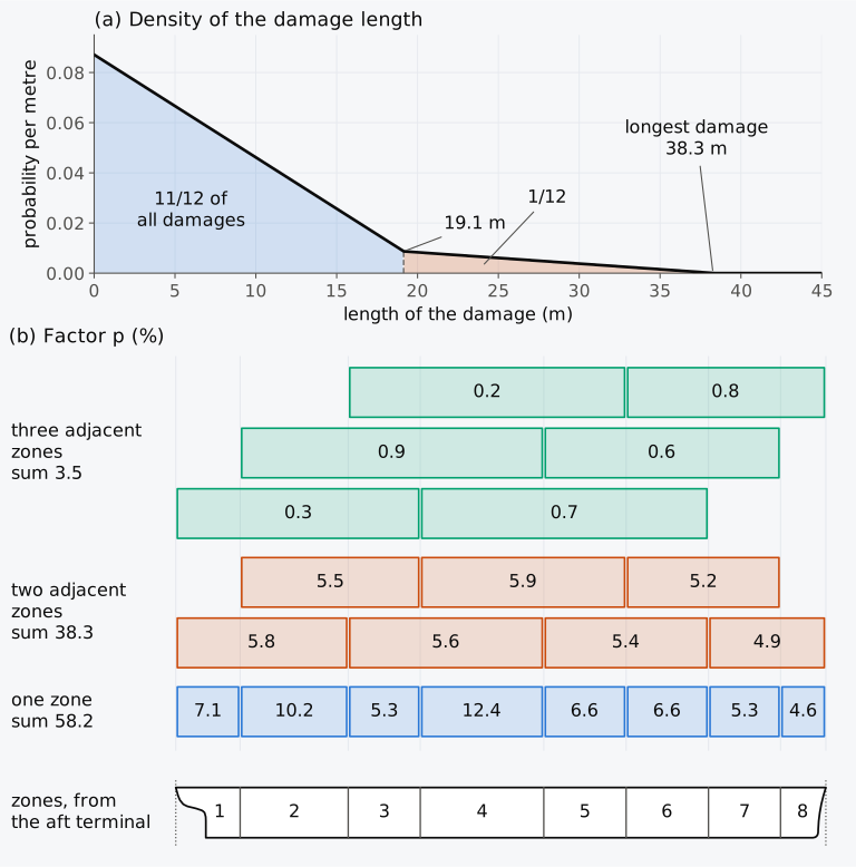
Figure 12.8 The factor p of SOLAS, regulation II-1/7-1, for the Series 60 ship, = 126.3 m: (a) the probability density of the length of damage; (b) the factor p of each zone and of each group of adjacent zones, in per cent. Groups of four zones add 0.05 %.
The factor s. For each damage, regulation II-1/7-2.1.1 of SOLAS11 takes as the least of and the product . The survival of the final stage depends on the curve of righting levers beyond the equilibrium heel , measured from upright towards the side to which the ship heels,
where , in metres, is the largest lever and Range, in degrees, the range of positive levers, both taken from up to the angle at which the lever vanishes or an opening that cannot be closed weathertight is submerged. is taken as no more than 0.12 m and Range as no more than 16°, except that a ro-ro passenger ship uses 0.20 m and 20° for each damage that involves a ro-ro space. For a cargo ship = 1 if is 25° or less, = 0 if is 30° or more, and in between; for a passenger ship the limits are 7° and 15°, and between them11. The regulation writes these angles as θ, but here φ is kept for heel and θ for trim. Intermediate stages are judged by a similar expression, with 0.05 m and 7°, for passenger ships and for cargo ships with cross-flooding devices. In those ships is zero if the heel at an intermediate stage exceeds 15° in a passenger ship or 30° in a cargo ship; for other cargo ships = 1 unless the Administration considers intermediate stability insufficient and requires further investigation11. The factor accounts for the heeling moments of crowding passengers, wind and launching survival craft in a passenger ship, and is 1 for a cargo ship11. The factor is also zero if the final waterline immerses the lower edge of an opening through which progressive flooding can take place into a space that the calculation does not already flood, such as an air pipe, a ventilator, or an opening closed by a weathertight door or hatch cover11; in a passenger ship built on or after 1 January 2024 the same holds at every intermediate stage of flooding11,17. A watertight deck above the waterline reduces by a factor , the probability that the damage does not reach above it, and = 1 when the boundary is the uppermost watertight deck11.
12.8.3 Minor damage, double bottoms and the collision bulkhead
Besides the probabilistic rules, passenger ships must survive some deterministic damages. A passenger ship carrying 36 or more persons must reach 0.9 after a minor damage along its side, whose length and penetration grow with the number of persons11. For 400 or more persons the damage is 0.03 long, but at least 3 m, with a penetration inboard of 0.1, but at least 0.75 m, and it extends from the baseline to 12.5 m above the deepest subdivision draught11. A ship carrying 400 or more persons must also reach = 1 with all the compartments within 0.08 of the forward perpendicular flooded11.
Every ship under the probabilistic rules must also meet two deterministic rules, for the double bottom and for the collision bulkhead. A double bottom is fitted from the collision bulkhead to the aft peak bulkhead as far as practicable11, with the inner bottom at least above the keel line, but not less than 0.76 m and not necessarily more than 2 m. Where it is not fitted, the ship must survive with = 1 a bottom damage (1/3) or 14.5 m long, whichever is less, and /6 wide, limited to 10 m within 0.3 of the forward perpendicular and to 5 m elsewhere. The damage extends /20 or 2 m above the keel line, whichever is less11; unlike , its height has no lower limit of 0.76 m. In a ship narrower than 15.2 m it is therefore lower than . The collision bulkhead stands at least 0.05 or 10 m, whichever is less, from the forward perpendicular, and not more than 0.08 or 0.05 + 3 m, whichever is greater11. The ship must reach = 1 with any part forward of it flooded without vertical limits, at the deepest subdivision draught, at level trim or any trim by the head11.
12.8.4 The attained index of the Series 60 ship
The attained index of the Series 60 ship needs three assumptions that the arrangement of Chapter 3 does not settle, and each of them affects . Openings closed by weathertight hatch covers count among those through which progressive flooding may take place11, but the arrangement has no hatchways. Each hold is given a hatchway of an assumed size on a coaming 0.600 m high, the height that the Load Line Convention prescribes for a hatchway in position 1, on an exposed freeboard deck13. The Convention also allows that height to be reduced, or the coaming omitted, for a hatchway whose covers meet reg. 16(2) to (5), where the Administration is satisfied that the safety of the ship is not thereby impaired in any sea conditions13, so 0.600 m is the standard height chosen for this illustrative arrangement rather than the lowest that the rules admit. Spaces intended for liquids are taken at 0 or 0.95, whichever gives the more severe requirement11. The more severe value is known only after both have been computed, and here the double bottoms and the peaks are taken as empty, with a single calculation for each damage. Finally, the explanatory notes suggest taking the GM at each draught first from the intact limit curve12. Here the KG at each draught is taken from the illustrative limiting curve of Table 11.6, which rests on the general criteria of the IS Code and leaves out the weather criterion, whose tables do not cover the ship at the light service draught. The calculation that follows therefore explores damage stability at these values of KG and is not a complete approval calculation.
Example 12.6. Attained subdivision index of the Series 60 ship. The Series 60 ship, = 121.92 m, = 16.256 m, = 9.754 m, is a cargo ship with a flat deck and no longitudinal bulkheads. Its transverse bulkheads stand at 9, 30, 44, 68, 84, 100 and 114 m from the AP, with a double bottom 1.2 m high between 9 m and 114 m, and the hull below the deck extends from 3.505 m aft of the AP to 122.804 m forward of it. The deepest subdivision draught is its summer draught, 6.502 m, and the light service draught is that of its ballast arrival condition, 3300.7 t, on even keel, 3.054 m. At each draught the ship floats on even keel with KG equal to the limiting value of Table 11.6, corrected for free surfaces, which is 6.343 m, 6.308 m and 7.090 m at , and . The holds have permeabilities of 0.70, 0.80 and 0.95 at the three draughts and the engine room 0.85, while 0.95 applies to the peaks and to the double bottoms, taken as empty11. Water can pass below the deck through a ventilator and through the hatchways. The ventilator, which cannot be closed weathertight, stands 40 m from the AP and 6.0 m to starboard of the centreline, with its opening 11.754 m above the baseline, and leads to the engine room. Each hold has a hatchway on the centreline, 8.0 m wide and 2 m clear of the bulkheads of the hold, except over hold 1, where it is 5.0 m wide and runs from 102 m to 108 m, and each hatchway has a weathertight cover on a coaming 0.600 m high. Find and , check the factor of hold 1, of the fore peak and of holds 2 and 1 together and the factor of holds 2 and 1 together at and of holds 3 and 2 together at , and judge the subdivision11.
Table 12.5 Factors and of the damages of the Series 60 ship in Example 12.6. Damages of four zones, with = 0.00051 together, are lost at every draught. Where = 0, the cause is given: “founders”, the hull up to its deck, less the flooded compartments, has less volume than the displacement; “plunges”, no trim within 42° by the head or the stern balances the ship, and it goes down by that end; “capsizes”, the lever is negative at every heel up to 60°; “hatchway”, the final waterline is above the coaming of the hatchway of an intact hold.
| Damage | at | at | at | |
|---|---|---|---|---|
| Aft peak | 0.07117 | 1 | 1 | 1 |
| Hold 5 | 0.10201 | 1 | 1 | 1 |
| Engine room | 0.05274 | 1 | 1 | 1 |
| Hold 4 | 0.12442 | 1 | 1 | 0, capsizes |
| Hold 3 | 0.06612 | 1 | 1 | 0, capsizes |
| Hold 2 | 0.06612 | 1 | 1 | 1 |
| Hold 1 | 0.05274 | 1 | 1 | 1 |
| Fore peak | 0.04637 | 1 | 1 | 1 |
| Aft peak and hold 5 | 0.05844 | 0.951 | 1 | 1 |
| Hold 5 and engine room | 0.05502 | 0, plunges by the stern | 1 | 1 |
| Engine room and hold 4 | 0.05635 | 0, plunges by the stern | 1 | 0, capsizes |
| Holds 4 and 3 | 0.05881 | 0, plunges by the head | 1 | 0, capsizes |
| Holds 3 and 2 | 0.05392 | 0, plunges by the head | 0, hatchway of hold 1 | 0.975 |
| Holds 2 and 1 | 0.05165 | 0.864 | 1 | 1 |
| Hold 1 and fore peak | 0.04888 | 1 | 1 | 1 |
| Aft peak, hold 5 and engine room | 0.00304 | 0, plunges by the stern | 0, capsizes | 1 |
| Hold 5, engine room and hold 4 | 0.00922 | 0, founders | 0, plunges by the stern | 0, plunges by the stern |
| Engine room, holds 4 and 3 | 0.00175 | 0, founders | 0, plunges by the head | 0, capsizes |
| Holds 4, 3 and 2 | 0.00664 | 0, founders | 0, plunges by the head | 0, plunges by the head |
| Holds 3, 2 and 1 | 0.00630 | 0, plunges by the head | 0, plunges by the head | 0, plunges by the head |
| Holds 2 and 1 and fore peak | 0.00779 | 0.720 | 1 | 1 |
| Partial index | 0.73637 | 0.91863 | 0.66857 |
With the damage limited to the double bottom, the lesser vertical extent, every zone gives = 1 at every draught, and no smaller damage is worse here. At the deeper draughts the ship is short of reserve buoyancy for pairs of holds amidships. A deeper hull or a watertight deck below the hatch covers would provide it, and the choice between them is left to the designer.
Where falls short of , the GM is raised at the draughts concerned, as the explanatory notes describe12. The selected GM values must satisfy both and the partial-index limits; because combines the draughts, there need not be a unique least GM at each one. The approved limit curve joins the GM values selected at , and by straight lines11. The stability information then gives the master, at each draught, a curve of minimum GM or of maximum KG that meets both the intact and the damage requirements, the more severe of the two11. For the Series 60 example at level trim, the values of KG taken from Table 11.6 give above , within the assumptions of Example 12.6.
12.9 Damage stability in industry today
This section describes practice in 2026, and its web pages were read on 19 October 2026.
The rules in force. This chapter follows the consolidated edition of SOLAS of 2024, whose parts on subdivision and stability apply to ships whose building contract is placed on or after 1 January 2020, to ships without a building contract whose keels are laid on or after 1 July 2020, and to every ship delivered on or after 1 January 2024, whatever the date of its contract11. On 1 January 2024 the amendments adopted by Resolution MSC.474(102) on 11 November 2020 entered into force17, and the edition includes them. For passenger ships built from that date, is zero if the lower edge of an opening through which progressive flooding may take place is immersed at any intermediate stage of flooding, not only at the final waterline, and the damage control information of those to which reg. II-1/8-1.3 applies must refer to the damage stability support of the onboard stability computer, if one is installed, and to shore-based support, where it is provided; for cargo ships the rule of the final waterline used in Example 12.6 is kept17.
Design and approval. Computers made it possible to examine many damage cases, some thousands for a passenger ship, and to follow the progress of flooding through ducts and non-watertight structure with time4. The explanatory notes accept computational fluid dynamics, time-domain flooding simulation or model tests as alternatives for intermediate stages of flooding and for the time to equalize12. Zone boundaries need not coincide with watertight bulkheads, and more zones generally give a higher attained index, at the cost of computing time12.
On board. The International Code on Intact Stability, 2008 (IS Code), accepts three types of stability software, of which Type 1 calculates intact stability only, Type 2 also checks damage stability against a limit curve or against loading conditions approved beforehand, and Type 3 calculates damage stability directly, for damage cases programmed in advance, in each loading condition18. Under the Guidelines for the approval of stability instruments, MSC.1/Circ.1229, every stability instrument is approved for the particular ship on which it is installed19, and the damage stability criteria of the Load Line Convention need not be shown in service with a stability instrument13. A passenger ship of 120 m or more, or with three or more main vertical zones, must have an onboard stability computer or shore-based support to give the master operational information after a flooding casualty. For ships constructed before 1 January 2014, this requirement applies from the first renewal survey after 1 January 2025, as SOLAS specifies11. Plans of the watertight compartments, their openings and closures, and the means of correcting a list are kept on the bridge, and the damage stability information must give the master a simple way to judge survival in every damage case11. Passenger ships hold damage control drills at least every three months11.
Water on the vehicle deck. The ro-ro passenger ship Estonia sank on 28 September 1994 on a voyage from Tallinn to Stockholm, and 852 of the 989 people on board died20. The Stockholm Agreement that followed, concluded in 1996 by eight northern European countries21, raised the stability standard of ro-ro passenger ships by taking account of water collecting on the vehicle deck after damage22. Directive 2003/25/EC set requirements of this form in the European Union, assuming a depth of water on the deck of 0.5 m when the residual freeboard is 0.3 m or less, none when it is 2.0 m or more, and values interpolated between21. Directive (EU) 2023/946 aligned the European rules with the stability requirements of IMO, as set out in SOLAS 2020, the Directive’s name for the Convention as last amended by Resolution MSC.421(98)23. New ro-ro passenger ships carrying more than 1350 persons must meet the probabilistic rules of SOLAS 2020, and those carrying 1350 or fewer may meet either the water-on-deck requirements or SOLAS 2020 with a higher required index23. Below 1000 persons on board that index is = 0.000088 + 0.7488, with the number of persons23.
Damage beyond the standard. On 13 January 2012 the cruise ship Costa Concordia, with 4229 persons on board, struck rocks off the island of Giglio, and the breach, 53 m long, flooded five contiguous watertight compartments; 32 lives were lost24. The Italian investigation found the damage “well beyond the survivability standard” that applied to the ship, which could withstand flooding of two adjacent main compartments24, although the ship complied with every SOLAS regulation that applied to it24. A ship can meet the required index and still be vulnerable to a particular casualty outside the assessed damages; the index does not express immunity to every possible loss4.
Research. European projects have studied the probabilistic rules and their parameters. HARDER, from 2000 to 2003, addressed the validation of the calculations, the choice of parameters and the levels of acceptance for the harmonized rules25. GOALDS, from 2009 to 2012, built a database of 1016 collisions, 472 groundings and 39 contacts, proposed an index that weights the attained index for collision by 0.71 and that for grounding by 0.29, and found that designing passenger ships for attained indices above 0.90 was cost-effective26. FLARE, from 2019 to 2022, worked on a risk-based method for the live assessment and control of flooding risk, and on a proposal to revise the IMO regulations towards a risk-based approach27.
12.10 From damage to support on the ground
In the final open-to-sea state, water enters and leaves the damaged compartments freely, and the equilibrium of the ship is found by removing buoyancy from the hull. A ship that touches the ground, rests on the blocks of a dock or slides down the ways at its launch is held instead by a force on its bottom. This force changes the draughts and trim and also reduces the stability, and it can be counted in two ways, much as the floodwater was counted by lost buoyancy and by added weight. In Chapter 13 we will look at these partly supported ships, in docking, grounding and launching.
Summary
- A compartment open to the sea fills to the level of the sea, and the ship sinks, trims and may list until the intact part of the hull supports the weight. The ship founders if the hull up to the deck cannot carry that weight, plunges if no acceptable trim balances the ship before flooding progresses, and can capsize if it cannot reach a stable heel; progressive flooding through openings or over bulkheads can take it past equilibrium.
- Permeability μ is the fraction of a space that water can occupy. For a cargo of stowage factor SF and solid density , μ = 1 − 1/( SF), Eq. (12.2). SOLAS takes 0.60 for stores, 0.85 for machinery, 0.95 for accommodation and voids, and 0.70, 0.80 and 0.95 for dry cargo at the deepest subdivision, partial subdivision and light service draughts.
- By lost buoyancy the displacement and G stay fixed and the waterplane loses . With the sides vertical over the sinkage, the ship sinks by δ = μ/( − ), Eq. (12.3), and BM is that of the intact waterplane. By added weight the water is a mass with a free surface. The two methods give a single waterline and equal righting moments, Δ· = ·, Eq. (12.7), but different GMs, and the method must be stated with the result.
- A compartment away from F′, the centre of the intact waterplane, trims the ship about F′ by ρμ()/(100 MCT′), Eq. (12.10); the estimate is linear and keeps the intact waterplane as the ship trims. A wing compartment lists the ship, and by added weight its free surface must then be taken about the axis through F′, since the slack-tank formula about its own centroid overstates GM. A smaller, unsymmetrical damage can be worse than a larger damage.
- The curve of righting levers after damage is computed directly by lost buoyancy, with the trim free, and freeboard governs it as much as GM does; the engine room and hold 4 together, for example, leave the Series 60 ship a GM larger than intact but a largest lever of only 0.080 m.
- An intermediate stage, with the water below the sea level and a free surface across the floor of the space, can be worse than the final stage, and hold 4 of the Series 60 ship gives a negative GM when water first covers its tank top.
- The floodable length is the greatest length, centred at a point, that can flood without submerging the margin line, at least 76 mm below the bulkhead deck, and a compartment drawn as a triangle lies within it if its apex lies below the curve. The factor of subdivision, already in the convention of 1914 and kept in SOLAS 1974, turned it into a permissible length; a ship whose single compartments fit is a one-compartment ship, and a ship whose pairs of adjacent compartments fit is a two-compartment ship.
- Deterministic damage standards remain in regulation 27 of Annex I of the Load Line Convention for Type A and reduced-freeboard Type B ships, in the instruments for tankers and gas carriers, in the minor damage of passenger ships and in the rules for double bottoms and collision bulkheads.
- For passenger ships and for cargo ships of 80 m and over, SOLAS asks for an attained index = 0.4 + 0.4 + 0.2, with = Σ, Eqs. (12.15) and (12.16), of at least , given for a cargo ship over 100 m by Eq. (12.17). Each partial index must be at least 0.5 in a cargo ship and 0.9 in a passenger ship. The factor comes from a distribution of damage length, Eq. (12.18), and from the curve of righting levers after damage, Eq. (12.19), with = 0 when the final waterline reaches an opening into an intact space. The Series 60 arrangement attains 0.796 against 0.540.
Notes on the data
The Titanic. The account follows the report of the British Wreck Commissioner’s inquiry, read in the transcription of the Titanic Inquiry Project, the report of the United States Senate’s Committee on Commerce, also transcribed there, and the evidence of Edward Wilding on the nineteenth day of the British inquiry1,2. Section titles of the reports are given as locators, and Wilding’s evidence by question number3. The two counts of lives lost come from the two reports, which counted differently. None of the data of the Titanic is used in the calculations, except Wilding’s estimates in Exercise 12.8.
The box barges. The two illustrative barges are 70 m × 13 m × 6.5 m at 3.30 m with KG = 3.90 m, used in Examples 12.2, 12.4 and 12.5 and Exercises 12.6 and 12.9, and 80 m × 14 m × 7 m at 3.50 m with KG = 4.20 m, used in Example 12.3 and Exercises 12.3 and 12.4. Their results follow from the closed forms of a wall-sided box, and the damage engine of the scripts, which floats the hull with the heel and the trim free, reproduces every printed value to 10⁻⁶ m; Fig. 12.4 shows the heel that it computes.
The Series 60 ship. The hull is the Series 60 surface of Chapter 1, closed by a flat deck at 9.754 m, as in Chapter 8, with no superstructure and no sheer. The arrangement is that of Chapter 3, bulkheads at 9, 30, 44, 68, 84, 100 and 114 m forward of the AP and a double bottom 1.2 m high between 9 m and 114 m. The fully loaded departure and arrival conditions are those of Chapter 11, with their free surface moments, 1573.5 t·m, applied as a virtual rise of G at every angle. The aft peak holds fresh water, which is lost with its free surface moment of 328.7 t·m when the peak is opened. The holds and the engine room are flooded above an intact double bottom, and the peaks from the baseline to the deck. Floating positions and levers are computed on the hull by lost buoyancy with the heel and the trim free, every degree to 60°. The hand estimates of Table 12.2 take the volume and waterplane of each hold from the hull below the departure waterline, 6.367 m, and the waterplane of the ship from Table 6.1, interpolated linearly at that draught.
The ventilator. The ventilator of Chapter 11, 2.0 m above the deck, 40 m forward of the AP and 6.0 m from the centreline, is illustrative, and for damage it is placed on the side to which the ship heels, the starboard side. It leads to the engine room, and in a damage that floods the engine room it admits no water that the calculation does not already count; it then neither ends the range of levers nor sets to zero.
Intermediate stages. The water enters the hold in 40 equal steps of its final volume, the volume found by lost buoyancy. At each step it is added as a mass at its own level, with the ship upright and free to trim, and the level inside and the trim are iterated until they agree. At the last step the water stands at the level of the sea, and the waterline is that of lost buoyancy. GM is corrected for the free surfaces of the tanks and of the water, μ /∇, and referred to the intact displacement. In Fig. 12.6 the stages of each hold are joined by straight lines.
Floodable length. The curves are computed every 2 m of the position of the centre, by lost buoyancy, at the summer draught on even keel with G on the vertical through the centre of buoyancy, for compartments from the baseline to the margin line. Upright tables of the sections give the floating positions with the trim free, and three points were checked on the heeled hull of Chapter 8, which places the margin line within 0.3 mm of the water. The terminals lie at the ends of the margin line, 3.484 m aft of the AP and 122.782 m forward of it. The floodable length of each compartment and of each pair of adjacent compartments between the peaks is computed directly at its centre, with a uniform permeability.
The attained index. The zones, draughts, KG, permeabilities and openings are those stated in Example 12.6. Every zone and every group of adjacent zones with > 10⁻⁹ is computed, 25 damages at each draught, and the double bottom by itself under each hold and the engine room as the lesser vertical extent. The lever curves run every degree from the equilibrium to 40°, and on while the lever is positive, with and Range taken on a cubic spline through them. Where the upright position is unstable, the equilibrium is the angle of loll on the starboard side. Because the searches are bounded, a damage for which no equilibrium heel is found within 60° is taken as a capsize, and a damage for which no trim is found within 42° by the head or by the stern, with enough volume up to the deck, is taken as a plunge, by the stern if the centre of buoyancy of the flooded ship on even keel lies forward of G and by the head if it lies aft.
Sensitivity of the attained index. The hatchway layout and the coaming height of Example 12.6 are illustrative; air pipes, doors and the deckhouse are not modelled, a deck under water is not taken as an opening, and a hatchway counts only when its hold is intact. Only in the damage of holds 3 and 2 at does an opening set to zero, the coaming of hold 1 being 3.218 m under water. In the damages that survive, the lowest opening into an intact space is the top of a coaming 0.385 m above the water, at , and any coaming from 0.22 m to 3.81 m high leaves unchanged. With no opening counted, = 0.813. The aft peak holds fresh water and some of the double bottoms fuel, diesel and lubricating oil in the arrangement of Chapter 3, the fore peak holds water ballast in some conditions of Chapters 10 and 11, and SOLAS takes a space intended for liquids at 0 or 0.95, whichever gives the more severe requirement11. With every double bottom full instead, at 0, and the peaks as before, = 0.754, and taking for each damage the lower of the two values of gives 0.722, with = 0.545. A full peak admits no water, so a damage that includes it floods only its other zones, whose in Table 12.5 is never lower; the empty peaks are therefore the more severe assumption, and with both peaks full = 0.799. With the KG of the ballast arrival condition corrected for free surfaces, 6.561 m, at instead of the limiting 7.090 m, = 0.893 and = 0.841. In all these cases exceeds and each partial index exceeds 0.5.
The modes of loss. Figure 12.2 shows three damages of Table 12.5, computed as for the attained index, each zone from the baseline up with its double bottom taken as void at 0.95: hold 5, the engine room and hold 4, and holds 3 and 2, at the deepest subdivision draught, 6.502 m, with KG = 6.343 m, and holds 4 and 3 at the light service draught, 3.054 m, with KG = 7.090 m. In (a) the hull up to its flat deck, upright and on even keel, less the floodwater, has a volume of 6824 m³, while the ship displaces 7709 m³. In (b) the ship is floated at its displacement with the trim by the head, 1.27°, at which the deck at the stem reaches the water; B then lies 5.41 m aft of G, and it stays aft of G at every trim up to 42° by the head. In (c) the lever with the trim free is negative at every heel from 5° to 60°, and the section is drawn at 64 m from the AP, the middle of the flooded length.
The animation. Animation 12.1 uses the 41 stages of hold 2 in the departure condition, computed as above.
Exercises
Under each exercise, “Show answers” opens its short answers and “Show full solution” its worked solution. Sea water has a density of 1.025 t/m³ and = 9.81 m/s². Heel is positive with the starboard side down, and trim is positive by the stern.
12.1 A hold has a volume of 2400 m³ below the waterline and is filled with a cargo that stows at 1.45 m³/t, the solid material of the cargo having a density of 1.60 t/m³. (a) Find the permeability of the loaded hold. (b) Find the volume and the mass of sea water that enter the hold when it is bilged. (c) Compare the volume with that given by the permeability that SOLAS assumes for a dry cargo space at the deepest subdivision draught, 0.70.
12.2 A box-shaped vessel 30.48 m long, 6.096 m wide and 6.096 m deep floats at 3.048 m, and a compartment 6.096 m long at mid-length, extending across the vessel from the bottom to the deck, is bilged. (a) Find the sinkage when the compartment is empty. (b) Find the permeability of the compartment when it is full of coal stowing at 1.226 m³/t, the solid coal having a density of 1.281 t/m³, and the sinkage when it is bilged. Adapted from Attwood9 (public domain), converted to SI.
12.3 A box barge 80 m long, 14 m wide and 7 m deep floats at 3.50 m in sea water with KG = 4.20 m. A compartment from 34 m to 46 m from its after end, across the whole breadth and above a double bottom 1.2 m high, is opened to the sea, with a permeability of 0.70. Find (a) the sinkage, (b) GM by lost buoyancy and (c) GM by added weight, and (d) show that the two give equal righting moments, in kN·m per radian of heel.
12.4 A box barge 80 m long, 14 m wide and 7 m deep floats at 3.50 m in sea water with KG = 4.20 m. A compartment from 34 m to 46 m from its after end, across the whole breadth and above a double bottom 1.2 m high, has a watertight flat 2.5 m above the baseline, below the waterline. The barge is bilged below the flat only, and the space between the tank top and the flat, with a permeability of 0.70, fills completely. Find the draught of the barge and its GM by lost buoyancy and by added weight.
12.5 A lighter 30.48 m long, 12.192 m wide and 3.048 m deep floats in sea water at 0.9144 m on even keel. Its collision bulkhead stands 1.8288 m from the forward end, and the compartment forward of it, extending across the lighter from the bottom, is opened to the sea. Using Eqs. (12.3) and (12.8) to (12.11), find the sinkage, the trim and the draughts at the ends, with MCT′ taken from the intact waterplane. Adapted from Attwood9 (public domain), converted to SI.
12.6 The box barge of Example 12.4, 70 m × 13 m × 6.5 m at 3.30 m with KG = 3.90 m and G on the centreline, has a wing compartment 3 m wide on its port side from 28 m to 42 m, extending from the bottom to the deck, with a permeability of 0.95. Find the angle of heel by lost buoyancy, first with the small-angle formula and then with the wall-sided formula.
12.7 A lighter 30.48 m long and 6.096 m wide floats at 1.2192 m with GM = 1.829 m, and its hold, between bulkheads 3.048 m from each end, extends across the whole breadth. (a) Show that a little water lying across the floor of the hold makes the lighter unstable. (b) Find GM if a watertight centreline bulkhead divides the hold. Neglect the weight of the water. Adapted from Attwood9 (public domain), converted to SI.
12.8 An ideal opening of area under a head admits of water per second, and openings with a total area of 1.115 m² lie 7.62 m below the waterline. (a) Find the ideal rate of inflow. (b) If 16,257 t of sea water entered in 40 minutes, find the mean rate of inflow and its ratio to the ideal rate.
12.9 The box barge of Example 12.5, 70 m × 13 m × 6.5 m with its margin line 76 mm below the deck, floats at 3.80 m. Find the floodable length at mid-length for permeabilities of 0.95 and 0.60, and the permissible length there for a factor of subdivision of 0.50 at 0.95.
12.10 At the summer draught, the floodable length of the Series 60 ship at the centre of each compartment, computed for a uniform permeability equal to that of the compartment, 0.60 for the holds and 0.85 for the engine room, the values that SOLAS 1974 took for cargo spaces and for spaces containing machinery in a detailed calculation of permeability10, is as follows: hold 5, 21.0 m long, 30.47 m; engine room, 14.0 m long, 20.82 m; hold 4, 24.0 m long, 50.04 m; hold 3, 16.0 m long, 23.94 m; hold 2, 16.0 m long, 21.82 m; hold 1, 14.0 m long, 31.56 m. (a) Find the smallest factor of subdivision that every compartment meets, and the compartment that sets it. (b) With a factor of 0.70, find the compartment that exceeds its permissible length.
12.11 In the departure condition, with hold 4 open, the Series 60 ship floats upright with = 0.481 m and 2.149 m of freeboard. With the engine room and hold 4 open the ship floats upright with = 0.779 m and 0.067 m of freeboard, with the margin line 9 mm under water; the largest lever is 0.080 m, and the levers vanish at 20.2°. Judge both cases against the equilibrium criteria of the Load Line Convention, regulation 27(13)(c) to (e)13, taking the first margin as not doubtful and the second as doubtful, and find by how much the second case misses or meets each limit of (e) that can be judged.
12.12 For the Series 60 ship, take the rule length as 121.92 m, the forward perpendicular 121.92 m forward of the AP and the breadth as 16.256 m. The collision bulkhead stands 114 m forward of the AP, and the inner bottom 1.2 m above the keel. (a) Check the position of the collision bulkhead against regulation II-1/12.1 of SOLAS11. (b) Check the height of the inner bottom against regulation II-1/9.2 of SOLAS11. (c) Find the length and breadth of the bottom damage of regulation II-1/9.8 away from the bow11.
12.13 Find as SOLAS regulation II-1/7-2.3 sets it11 for (a) a cargo ship floating upright after damage, with = 0.09 m and a range of 12°, (b) a cargo ship heeled to 27° after damage, with = 0.15 m and a range of 20° beyond that heel, and (c) a passenger ship heeled to 10°, with = 0.10 m and a range of 14°.
12.14 A cargo ship with = 120 m is divided into six zones. The factors are 0.1185, 0.1181, 0.1181, 0.1181, 0.0870 and 0.1185 for the single zones from aft, 0.0631, 0.0632, 0.0632, 0.0609 and 0.0608 for the pairs of adjacent zones from aft, and 0.0021, 0.0021, 0.0021 and 0.0043 for the groups of three. At every single zone has = 1, the pairs from aft have = 1, 0.8, 0, 0 and 1, and the groups of three 0. At every single zone has = 1, the pairs 1, 1, 0.6, 0.5 and 1, and the groups of three 0. At the single zones have = 1 except the third, with 0.9, every pair has = 1, and of the groups of three only the aftmost survives, with = 1. Find , , , and , and judge the subdivision by regulation II-1/6 of SOLAS11.
Symbols introduced in this chapter
Symbols defined in earlier chapters, among them φ, θ, GZ, GM, , KB, BM, KG, F, , , , , , , , MCT, , , , , , , , and SF, keep their meaning. In this chapter, GM, and GZ of a damaged ship are those of lost buoyancy at the intact displacement, and denotes the volume of a space, not the factor of SOLAS.
| Symbol | Meaning | Unit |
|---|---|---|
| μ, | volume and surface permeability of a space | – |
| , | moulded volume of a space, or of the part of it below the waterline, and the volume of water it can hold | m³ |
| density of the solid material of a cargo | t/m³ | |
| , | area of the waterplane within a compartment, and its centroid forward of the AP | m², m |
| centroid of the volume of a compartment forward of the AP | m | |
| δ, | parallel sinkage, and the draught after it | m |
| F′, , | centre of the intact waterplane, and its position | m |
| , | transverse and longitudinal second moments of the intact waterplane about axes through F′ | m⁴ |
| transverse second moment of the whole waterplane about the axis through F′ | m⁴ | |
| , | transverse and longitudinal second moments of a compartment’s waterplane | m⁴ |
| transverse second moment of the surface of the water in a hold that is filling | m⁴ | |
| KB′, BM′, , , MCT′ | hydrostatics of the ship by lost buoyancy | m, t·m/cm |
| centre of buoyancy of a flooded box on even keel, forward of the AP | m | |
| , | metacentric height by lost buoyancy and by added weight | m |
| , , | mass of water admitted, the height of its centroid, and the volume of the compartment below the final waterline | t, m, m³ |
| , , , , , | displacement, volume and hydrostatics by added weight | kN, t, m³, m |
| , | transverse centroid of a compartment and of the buoyancy after flooding, positive to port | m |
| , , , , | time to equalize through a duct, volume transferred, area of the duct, initial head, flow coefficient | s, m³, m², m, – |
| distance of the centre of a compartment from a terminal of the floodable length | m | |
| factor of subdivision | – | |
| draught at which the waterline reaches the margin line, for a box | m | |
| floodable length | m | |
| , , , , | attained subdivision index and its partial indices | – |
| required subdivision index | – | |
| , , | deepest subdivision, partial subdivision and light service draughts | m |
| subdivision length | m | |
| , , , | probability of a damage, probability of survival, factor for a longitudinal bulkhead, factor for a horizontal boundary | – |
| , | length of a damage, and the non-dimensional damage length | m, – |
| , | value of at which the density changes slope, 5/33, and the lesser of and 10/33 | – |
| , , , | coefficients of the two pieces of the density of | – |
| , , | factors of survival of the final stage, the intermediate stages and heeling moments | – |
| , Range | largest lever and range of positive levers beyond , up to | m, ° |
| , | equilibrium heel after damage, and the angle at which the lever vanishes or an unprotected opening is submerged | ° |
| factor of for the equilibrium heel | – | |
| least height of the inner bottom above the keel line | m | |
| number of persons on board | – | |
| area of an opening through which water enters | m² |
Corrections
Corrections to version 1.0, released on 3 November 2026, with their dates.
- 3 November 2026. The chapter cites SOLAS in its consolidated edition of 2024, in place of that of 2020.
- 3 November 2026. Sec. 12.8.2 adds that in a passenger ship built on or after 1 January 2024 an opening through which progressive flooding may take place sets to zero when it is immersed at an intermediate stage of flooding too, as amended by Resolution MSC.474(102).
- 3 November 2026. Sec. 12.9 explains that the “SOLAS 2020” of Directive (EU) 2023/946 is SOLAS as last amended by Resolution MSC.421(98).
- 3 November 2026. The method statement of Calculator 12.1 names its source in this chapter, Secs. 12.3 and 12.4.1.
- 4 November 2026. Sec. 12.9 states the applicability date for onboard stability computers or shore-based support on older passenger ships without presenting it as a future deadline.
- 5 November 2026. The prologue, Sec. 12.7.3 and the summary say that the factor of subdivision was already in the regulations of the convention of 1914, which tabulated it against the length of the ship and left the criterion of service to further study; they no longer date it to 1929 or to later conventions.
- 5 November 2026. The historical note of Sec. 12.8.2 says that the probabilistic rules for cargo ships were extended to those of 80 m and over in 1998, by Resolution MSC.47(66), and that the rules in force since 2009 apply to cargo ships of 80 m and over and to passenger ships; it cites the three resolutions.
- 5 November 2026. Example 12.2 now prints the intact righting-moment product, and Table 12.1 now states its printed-intermediate basis. The intact moment per radian remains 60927 kN·m.
- 5 November 2026. Sec. 12.3.4 says that Eq. (12.6) in the form given holds for symmetric flooding, and that for an unsymmetrical compartment both second moments are taken about the axis through F′. The route for a first reading says that the fourth outcome belongs to the second reading, with Sec. 12.7, and “What it assumes” names the limit of Table 11.6 as that of the general criteria.
- 6 November 2026. The chapter writes “Load Line Convention”, as the other chapters do, in place of “Load Lines Convention”, and Exercise 12.11 names the Convention in place of “Load Lines Annex I”.
References
- Wreck Commissioner’s Court. (1912). Report on the loss of the “Titanic” (s.s.) (Cd. 6352; formal investigation before Lord Mersey, Wreck Commissioner; dated 30 July 1912). Titanic Inquiry Project. Retrieved October 19, 2026, from https://www.titanicinquiry.org/BOTInq/BOTReport/botRep01.php Cited: ↑ "The collision" · ↑ "Time in which the damage was done" · ↑ "Watertight compartments" · ↑ "Watertight compartments" · ↑ "Structure" · ↑ "The flooding in the first 10 minutes" · ↑ "Gradual effect of the damage" · ↑ "Observations" · ↑ "Final effect of the damage" · ↑ "Introduction" · ↑ "Extent of the damage" · ↑ "Observations" · ↑ "Effect of additional subdivision on flotation" · ↑ "Effect of additional subdivision on flotation" · ↑
- United States Senate, Committee on Commerce. (1912). “Titanic” disaster: Report of the Committee on Commerce, United States Senate, pursuant to S. Res. 283 (S. Rep. No. 806, 62d Cong., 2d Sess.). Titanic Inquiry Project. Retrieved October 19, 2026, from https://www.titanicinquiry.org/USInq/USReport/AmInqRep01.php Cited: ↑ "First damage reported" · ↑ "Flooding of the vessel" · ↑ "Ship sinking" · ↑ "Summary of passengers and survivors" · ↑ "Flooding of the vessel" · ↑
- Wilding, E. (1912). Evidence to the British Wreck Commissioner’s inquiry into the loss of the “Titanic”, day 19, 7 June 1912. Titanic Inquiry Project. Retrieved October 19, 2026, from https://www.titanicinquiry.org/BOTInq/BOTInq19Wilding03.php Cited: ↑ Q. 20422 · ↑ Q. 20364 · ↑
- Tupper, E. C. (2013). Introduction to naval architecture (5th ed.). Butterworth-Heinemann. Cited: ↑ p. 97 · ↑ p. 94 · ↑ p. 94 · ↑ pp. 98–99 · ↑ p. 98 · ↑ p. 98 · ↑ p. 102 · ↑ p. 94 · ↑ p. 94 · ↑ pp. 94–95 · ↑ p. 95 · ↑ p. 96 · ↑ p. 97 · ↑ p. 106 · ↑ pp. 102–103 · ↑ p. 95 · ↑ pp. 102–103 · ↑ p. 103 · ↑ p. 106 · ↑ pp. 106–107 · ↑ pp. 102–103 · ↑ p. 107
- International Conference on Safety of Life at Sea. (1914). Text of the convention for the safety of life at sea, signed at London, January 20, 1914 (Cd. 7246). Internet Archive. Retrieved October 19, 2026, from https://archive.org/details/textofconvention00inte Cited: ↑ Art. 17 · ↑ Art. 30 and Regulations, Art. VIII · ↑ Regulations, Art. VIII
- Biran, A., & López-Pulido, R. (2014). Ship hydrostatics and stability (2nd ed.). Butterworth-Heinemann. Cited: ↑ p. 260 · ↑ p. 264 · ↑ p. 263 · ↑ p. 263 · ↑ p. 264 · ↑ p. 264 · ↑ p. 266 · ↑ p. 266 · ↑ p. 266 · ↑ p. 284 · ↑ p. 273
- Nickum, G. C. (1988). Subdivision and damage stability. In E. V. Lewis (Ed.), Principles of naval architecture: Vol. I. Stability and strength (2nd rev., ch. III). Society of Naval Architects and Marine Engineers. Cited: ↑ p. 144 · ↑ pp. 144–145 · ↑ p. 143 · ↑ p. 146 · ↑ p. 146 · ↑ pp. 146–147 · ↑ p. 146 · ↑ p. 190 · ↑ p. 160 · ↑ p. 160 · ↑ p. 160 · ↑ pp. 160–162 · ↑ p. 175 · ↑ p. 183 · ↑ p. 173 · ↑ p. 175 · ↑ pp. 176–177 · ↑ p. 146 · ↑ p. 170 · ↑ p. 176 · ↑ pp. 143 and 145 · ↑ p. 146 · ↑ p. 159 · ↑ p. 144 · ↑ pp. 144 and 194 · ↑ p. 194 · ↑ p. 195 · ↑ pp. 144–145
- Barrass, C. B., & Derrett, D. R. (2006). Ship stability for masters and mates (6th ed.). Butterworth-Heinemann. Cited: ↑ p. 213 · ↑ pp. 216–217 · ↑ pp. 218–219 · ↑ pp. 369–371
- Attwood, E. L. (1899). Text-book of theoretical naval architecture. Longmans, Green, and Co. (Public domain.) Cited: ↑ p. 34 · ↑ pp. 33–34 · ↑ p. 155 · ↑ pp. 32–34 · ↑ pp. 153–155 · ↑ p. 131
- International Convention for the Safety of Life at Sea, 1974, Nov. 1, 1974, 1184 U.N.T.S. 2. Cited: ↑ reg. II-1/2(e) and 2(f) · ↑ reg. II-1/7(d)(iv) · ↑ reg. II-1/7(c) · ↑ reg. II-1/3(b) · ↑ reg. II-1/2(g) · ↑ ch. II-1, Part B · ↑ reg. II-1/5(b) · ↑ reg. II-1/5(c) · ↑ reg. II-1/6(i) · ↑ reg. II-1/6(g) · ↑ reg. II-1/7(d) and 7(f) · ↑ reg. II-1/4(e)
- IMO. (2024). SOLAS: Consolidated edition 2024 (Sales No. IH110E). International Maritime Organization. Cited: ↑ reg. II-1/7-3.1 · ↑ reg. II-1/2.10 to 2.12 · ↑ reg. II-1/7-3.2 · ↑ reg. II-1/7-3.3 · ↑ reg. II-1/7-3.2 · ↑ reg. II-1/7.3 · ↑ reg. II-1/7.5 · ↑ reg. II-1/7-2.5 · ↑ reg. II-1/7-2.2 · ↑ reg. II-1/7-2.2 · ↑ reg. II-1/4.2.1.2 · ↑ reg. II-1/4.2.1.2 · ↑ reg. II-1/7.1 · ↑ reg. II-1/6.1 · ↑ reg. II-1/7.2 · ↑ reg. II-1/7.3 · ↑ reg. II-1/7.6 · ↑ reg. II-1/6.2.1 · ↑ reg. II-1/6.2.3 · ↑ reg. II-1/2.1 · ↑ reg. II-1/7-1.1.1 · ↑ reg. II-1/7-1.1 and 7-1.1.1 · ↑ reg. II-1/7-1.1.2 · ↑ reg. II-1/7-2.1.1 · ↑ reg. II-1/7-2.1 and 7-2.3 · ↑ reg. II-1/7-2.2 · ↑ reg. II-1/7-2.4 · ↑ reg. II-1/7-2.5.2.1 and 7-2.5.2.3 · ↑ reg. II-1/7-2.5.3.4 · ↑ reg. II-1/7-2.6 · ↑ reg. II-1/8.2 · ↑ reg. II-1/8.3 · ↑ reg. II-1/8.1 · ↑ reg. II-1/9.1 and 9.2 · ↑ reg. II-1/9.6 and 9.8 · ↑ reg. II-1/12.1 · ↑ reg. II-1/12.2 · ↑ reg. II-1/7-2.5.2.1 · ↑ reg. II-1/7-3.1 · ↑ reg. II-1/7-3 · ↑ reg. II-1/6.1 · ↑ reg. II-1/7-2.5.2.1 · ↑ reg. II-1/7.2 · ↑ reg. II-1/5-1.4 · ↑ reg. II-1/5-1.2.1 · ↑ reg. II-1/1.1.1 · ↑ reg. II-1/8-1.1 and 8-1.3 · ↑ reg. II-1/19.1 and 19.4 · ↑ reg. II-1/19-1.2 · ↑ reg. II-1/7-3.1 · ↑ reg. II-1/12.1 · ↑ reg. II-1/9.2 · ↑ reg. II-1/9.8 · ↑ reg. II-1/7-2.3 · ↑ reg. II-1/6.1 and 6.2.1
- IMO. (2020c). Revised explanatory notes to the SOLAS chapter II-1 subdivision and damage stability regulations (Resolution MSC.429(98)/Rev.2, adopted 11 November 2020; applies from 1 January 2024, when it revoked Resolution MSC.429(98)/Rev.1). Text consulted as the annex to Maritime and Coastguard Agency, MGN 692 (M) (2023). Retrieved October 14, 2026, from https://assets.publishing.service.gov.uk/media/65817268ed3c34000d3bfb39/MGN_692_Annex.pdf Cited: ↑ notes 1, 3, 3.1 and 3.1.1 to reg. II-1/7-2.2 · ↑ note 3 to reg. II-1/7-2.2 · ↑ Part A, 7 · ↑ note 1 to reg. II-1/7-1.1.1 · ↑ note 6 to reg. II-1/7.1 · ↑ note 6 to reg. II-1/7.1 · ↑ note 12 to reg. II-1/7-2.2 · ↑ note 3 to reg. II-1/7-1.1.1
- IMO. (2018). Load lines: Consolidated edition 2018. International Maritime Organization. Cited: ↑ Annex I, reg. 27(3) · ↑ Annex I, reg. 27(8) · ↑ Annex I, reg. 27(9) · ↑ Annex I, reg. 27(10) · ↑ Annex I, reg. 27(11) · ↑ Annex I, reg. 27(12) · ↑ Annex I, reg. 27(13)(a) · ↑ Annex I, reg. 27(13)(c) and 27(13)(d) · ↑ Annex I, reg. 27(13)(e) · ↑ Annex I, regs 13 and 14-1(1) · ↑ Annex I, reg. 14-1(2) · ↑ Annex I, reg. 27(13)(g) · ↑ Annex I, reg. 27(13)
- IMO. (1990). Adoption of amendments to the International Convention for the Safety of Life at Sea, 1974 (Resolution MSC.19(58), adopted 25 May 1990; in force 1 February 1992). International Maritime Organization. Retrieved November 5, 2026, from https://wwwcdn.imo.org/localresources/en/KnowledgeCentre/IndexofIMOResolutions/MSCResolutions/MSC.19(58).pdf Cited: ↑ Annex, reg. II-1/25-1
- IMO. (1996). Adoption of amendments to the International Convention for the Safety of Life at Sea, 1974 (Resolution MSC.47(66), adopted 4 June 1996; in force 1 July 1998). International Maritime Organization. Retrieved November 5, 2026, from https://wwwcdn.imo.org/localresources/en/KnowledgeCentre/IndexofIMOResolutions/MSCResolutions/MSC.47(66).pdf Cited: ↑ Annex, item 5, reg. II-1/25-1
- IMO. (2006). Amendments to the International Convention for the Safety of Life at Sea, 1974, as amended (Resolution MSC.216(82), adopted 8 December 2006; Annex 2 in force 1 January 2009). International Maritime Organization. Retrieved November 5, 2026, from https://wwwcdn.imo.org/localresources/en/KnowledgeCentre/IndexofIMOResolutions/MSCResolutions/MSC.216(82).pdf Cited: ↑ Annex 2, regs II-1/4.1 and 7
- IMO. (2020a). Amendments to the International Convention for the Safety of Life at Sea, 1974, as amended (Resolution MSC.474(102), adopted 11 November 2020; in force 1 January 2024). Text consulted in the copy of the Lithuanian Transport Safety Administration. Retrieved October 19, 2026, from https://ltsa.lrv.lt/uploads/ltsa/documents/files/TJO/MSC_474(102).pdf Cited: ↑ reg. II-1/7-2.5.3.4 · ↑ paras 2 and 3 · ↑ regs II-1/7-2.5.2.1, 7-2.5.3.4 and 19.5
- IMO. (2020b). International Code on Intact Stability, 2008 (2020 ed.; Resolution MSC.267(85), as amended, with the Explanatory Notes, MSC.1/Circ.1281). International Maritime Organization. Cited: ↑ Part B, 4.1.3
- IMO. (2007). Guidelines for the approval of stability instruments (MSC.1/Circ.1229, 11 January 2007). International Maritime Organization. Cited: ↑ annex, 3
- Swedish Accident Investigation Authority. (2020). The MV ESTONIA accident 1994 [Web page; last updated 2 October 2020]. Retrieved October 19, 2026, from https://shk.se/engelska/the-swedish-accident-investigation-authority/areas-of-investigation/maritime/the-mv-estonia–accident-1994 Cited: ↑
- European Parliament & Council of the European Union. (2003). Directive 2003/25/EC of the European Parliament and of the Council of 14 April 2003 on specific stability requirements for ro-ro passenger ships. Official Journal of the European Union, L 123, 22. Retrieved October 19, 2026, from https://www.legislation.gov.uk/eudr/2003/25/introduction/data.htm Cited: ↑ recital 10 · ↑ Annex I, 1.1
- Maritime and Coastguard Agency. (2014). Statutory consultation: Proposed revocation of four sets of maritime regulations [Consultation letter of 2 June 2014, with its impact assessment]. Retrieved October 19, 2026, from https://assets.publishing.service.gov.uk/government/uploads/system/uploads/attachment_data/file/312182/prposed-revocation-4-package.pdf Cited: ↑ impact assessment, p. 7
- European Parliament & Council of the European Union. (2023). Directive (EU) 2023/946 of the European Parliament and of the Council of 10 May 2023 amending Directive 2003/25/EC as regards the inclusion of improved stability requirements and the alignment of that Directive with the stability requirements defined by the International Maritime Organization. Official Journal of the European Union, L 128, 1–10. Retrieved October 19, 2026, from https://eur-lex.europa.eu/eli/dir/2023/946/oj/eng Cited: ↑ p. 3 · ↑ p. 5 · ↑ p. 8
- Ministry of Infrastructures and Transports, Marine Casualties Investigative Body. (n.d.). Cruise ship Costa Concordia: Marine casualty on January 13, 2012. Report on the safety technical investigation. Retrieved October 19, 2026, from https://www.sintef.no/globalassets/project/hfc/documents/costa_concordia_-_full_investigation_report.pdf Cited: ↑ pp. 4–6 · ↑ pp. 4 and 31 · ↑ p. 10
- European Commission. (n.d.-c). HARDER: Harmonisation of rules and design rationale (Contract G3RD-CT-1999-00028) [Project record]. CORDIS. Retrieved October 19, 2026, from https://cordis.europa.eu/project/id/G3RD-CT-1999-00028 Cited: ↑
- European Commission. (n.d.-a). Final report summary: GOALDS (GOAL Based Damage Stability) [Project record]. CORDIS. Retrieved October 19, 2026, from https://cordis.europa.eu/project/id/233876/reporting/it Cited: ↑
- European Commission. (n.d.-b). FLARE: FLooding Accident REsponse (Grant agreement ID 814753) [Project fact sheet]. CORDIS. Retrieved October 19, 2026, from https://cordis.europa.eu/project/id/814753 Cited: ↑