
In his textbook of 1899, Attwood came to the free surface through the inclining experiment. No free water may remain in a ship while it is inclined, he wrote, and its boilers are either emptied or run up quite full7. Working out why, he found that the water of a slack tank acts as if it were raised to its virtual centre of gravity, and that the metacentric height is reduced by the second moment of the free surface divided by the displaced volume7. The amount of water does not enter, and a small quantity of water with a large free surface has more effect than a large quantity with a smaller free surface7.
Figures and tables have more room in landscape.
Chapter 5: Moving, suspended and liquid loads
Version 1.0 · last revised 6 November 2026 · corrections
Prologue: the Herald of Free Enterprise
On the evening of 6 March 1987 the roll-on roll-off passenger ferry Herald of Free Enterprise left its berth at Zeebrugge for Dover with about 459 passengers, 80 crew, 81 cars and 47 freight vehicles on board. The ship sailed at 18.05, passed the outer mole at 18.24, and about four minutes later capsized, less than seven cables (about 1.3 km) from the harbour entrance. It came to rest on its port side in shallow water, with the starboard side above the surface. Not fewer than 150 passengers and 38 of the crew died1. The Herald was a modern ship, built in 1980, 131.9 m long overall and 22.7 m in breadth1, and at departure its metacentric height was calculated at 2.09 m, corrected for the liquids in the tanks1. That is about four times the metacentric height of the loaded Series 60 cargo ship, 0.526 m, also corrected for its liquids. The court thought it probable that the ship was heavier, near an upper estimate with a metacentric height of 2.04 m, and overloaded1.
The court that investigated the loss found that the ship had gone to sea with its inner and outer bow doors open1. The berth at Zeebrugge had a single ramp, and to load the upper of the two vehicle decks the ship had been trimmed by the head by filling ballast tanks forward. It sailed with the bow about 0.75 m deeper than the stern1. As it worked up to speed outside the mole, the bow wave rose well up the open doorway, and water poured over the spade, a horizontal platform at the bow that supported the doors, and along the main vehicle deck, a single open space running the length of the ship under the superstructure1. Within a short time, with the water spreading across a deck 22.7 m wide, the Herald lurched to port through perhaps 30°, so quickly that the court described the lurch as “extremely rapid”. The ship lay for a moment at a large angle and then rolled on past 90° as more water came in through the doorway1.
The rapid loss of stability came from the freedom of the water to move. The weight of the water also changed the ship’s displacement, centre of gravity and freeboard. A layer of liquid lying across a wide deck runs to the low side as soon as the ship inclines, and its movement acts on the ship like a rise of the ship’s centre of gravity. For water lying across the full breadth of a deck like the Herald’s, that rise is of the order of metres, and it can be calculated. In Sec. 5.3.5 we will isolate this free surface effect using the Herald’s departure condition: in that simplified calculation, water covering less than 20 m of the length of its vehicle deck uses up the whole of its 2.09 m of metacentric height. This illustrates the mechanism; it does not reconstruct the flooding during the accident.
So far we have treated every weight on board as fixed in the ship. The centre of gravity G came from the weight table and stayed where it was while the ship heeled. In service, however, weights move: cargo is loaded, discharged and restowed, and sometimes it shifts in a seaway; a load hanging from a crane stays vertical while the ship heels; and fuel, water and liquid cargo are carried in tanks that are rarely full. In this chapter we will look at each of these movements in turn, and then put them together in the stability calculation that a ship’s officer makes before every departure.
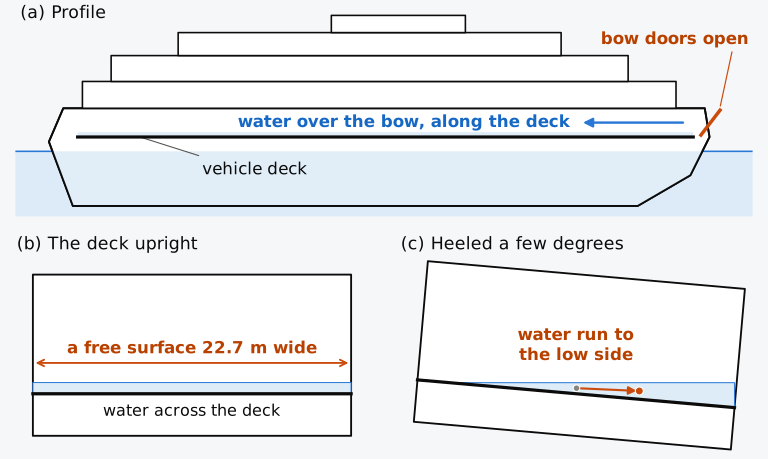
Figure 5.1 Water on a vehicle deck (schematic, not to scale): (a) a roll-on roll-off ferry with its bow doors open; (b) the deck upright; (c) the deck heeled a few degrees. The breadth, 22.7 m, is that of the Herald of Free Enterprise1.
In this chapter
By the end of this chapter you will be able to:
- find the movement of G and the change of GM when a mass is moved, loaded or discharged;
- find GM and the list while a load hangs from a crane;
- compute the free surface correction of a slack tank, and the effect of dividing or joining tanks;
- find the fluid GM of a loading condition;
- estimate the virtual rise of G from water lying across a deck, as on the Herald of Free Enterprise.
What it assumes. You need the metacentric height and the wedges of a small heel (Secs. 4.2 to 4.4), and the angle of list, Eq. (4.16). For larger angles you also need the wall-sided formula of Sec. 4.7.2.
A first reading. Sections 5.1 to 5.3 and 5.5 carry the main thread. Section 5.4, on bulk cargoes that shift or liquefy, is a specialist case with codes of its own and can wait for a second reading.
5.1 Effect of shifting, adding and removing weights
5.1.1 Shifting a weight on board
The centre of gravity of a ship is found by taking moments of all the weights on board, and in Chapter 4 these moments gave the movement of G when a mass was moved across the deck. Nothing in that argument depends on the direction of the movement. When a mass already on board is moved through a distance , the centre of gravity of the whole ship moves parallel to the movement, through
where is the displacement mass, which does not change, since nothing has been added or removed. The three movements of Fig. 5.2 have different effects. Moved upwards, a mass raises G and reduces GM by GG′, because KM depends only on the hull and the draught, and neither has changed. Moved across the ship, it moves G off the centreline and the ship lists; moved along the ship, it moves G forward or aft and the ship trims. A movement in any other direction can be split into these three components, each with its own effect.
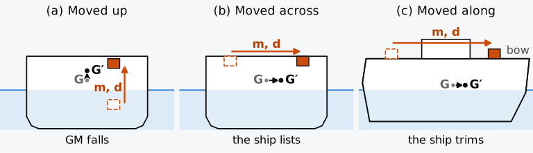
Figure 5.2 A mass moved upwards, across and along the ship (schematic).
5.1.2 Adding or removing a weight
When a mass is loaded or discharged, the displacement changes as well as the position of G. The new height of G is found from the moments about the keel, as in a weight table. Loading masses at heights gives
with a discharged mass entered as negative. The transverse and longitudinal positions of G are found by taking moments as in Eq. (5.2), with and in place of . The centre of gravity of a ship moves towards a mass that is added, away from a mass that is removed, and parallel to the movement of a mass that is shifted, each time through the mass times its distance divided by the final displacement2.
A loaded mass also makes the ship float deeper, and KM changes with the draught; whether GM goes up or down depends on both changes. Write the new metacentric height as , with read from the hydrostatic curves at the new draught. Subtracting GM and using Eq. (5.2) for a single mass loaded at height gives
By the second term, a mass loaded below G raises GM, a mass loaded above G lowers it, and the effect grows with the distance of the mass from G. The first term is the change of KM with the draught, which can be of either sign. Setting the change of GM to zero gives the height at which a mass may be loaded without changing GM,
This neutral height lies above G when KM rises with the draught, and below G when KM falls. On a box barge KM falls with the draught over most of its range, so a mass must be loaded below G to leave GM unchanged. On the Series 60 ship at its loaded draughts KM rises slowly, and the neutral height lies a little above G. How GM changes with the height at which a mass is loaded on this ship can be seen in Fig. 5.3, for two masses.
Predict 5.1. The Series 60 ship in its departure condition has KG = 5.887 m. A mass of 300 t is to be loaded. Before you read on, say whether loading it exactly at the height of G, 5.887 m, leaves GM unchanged, raises it or lowers it, and why.
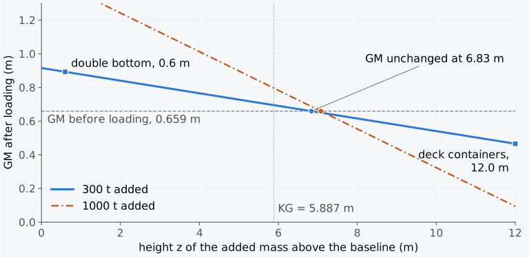
Figure 5.3 GM of the Series 60 ship in its departure condition after 300 t or 1000 t is added at a height , with KM at the new draught; dashed, GM before loading.
Example 5.1. Where to put 300 t. The Series 60 ship in its departure condition displaces 7707 t, with KG = 5.887 m, KM = 6.546 m (6.5458 m to four decimals) and GM = 0.659 m. With 300 t more on board it floats at a draught of 6.575 m, where KM is 6.581 m (6.5813 m). Find GM if the 300 t is stowed (a) as containers on the hatch covers with their centre 12.0 m above the baseline and (b) in the double bottom at 0.6 m. (c) Find the height at which the 300 t would leave GM unchanged.
The neutral height depends on the mass, because the change of KM does: for 1000 t it is 7.08 m on this ship (Fig. 5.3). It is not a number found in a ship’s stability information. In practice, cargo stowed high reduces GM and cargo stowed low increases it, by an amount found from the weight table and the hydrostatic table together.
5.1.3 Rise of G in service
A ship can arrive with much less GM than it sailed with, although nothing on board has been moved upwards. The Series 60 ship sails with GM = 0.659 m and arrives with 0.368 m. The fuel oil burned from its double bottom, 328 t taken from below G, raises G by 0.24 m. The diesel oil burned raises it by a further 0.02 m, and the fresh water and stores used lower it by about as much, since they lay above G. The remaining 0.05 m is the fall of KM as the ship rises out of the water. The tanks that the fuel leaves slack also have free surfaces, which act as a further rise of G. On most ships fuel and water are carried low, and their consumption is usually the largest change of a voyage, a loss of low weight that can be made good with sea water in segregated ballast tanks3; this ship carries its fresh water high, in the aft peak. Weight can also be gained high up, as ice on decks and rigging or as water taken up by timber carried on deck, two of many causes of a rise of G2; the International Code on Intact Stability, 2008 (IS Code), assumes a timber deck cargo to weigh 10 % more on arrival4. The IS Code’s standard loading conditions for a cargo ship include the arrival, with a tenth of its stores and fuel left, as well as the departure, and a condition that needs water ballast is calculated with that ballast on board4.
5.2 Effect of suspended weights
5.2.1 A weight hanging from a crane
Suppose a load of mass hangs from the head of a crane by a rope, and the ship heels slowly to a small angle (Fig. 5.4). We consider the load after it has settled, neglecting accelerations of the ship and load. The rope is then vertical, and the load has swung out towards the low side until it is again directly below the point of suspension S. The load acts on the ship only through the rope, which pulls down on the crane head at S, along the vertical, with the weight of the load. A mass fixed to the ship at S would exert a force equal to the pull of the rope at every angle of heel, since the weight of a fixed mass also acts along the vertical through the point where the mass is. For these static forces and moments on the ship, therefore, a hanging load is a mass at its point of suspension, and the height of the load below that point does not matter3,5. A bag carried by its handles behaves in this way: when the person carrying it leans to one side, the bag swings until it hangs straight below the hand again, and its weight is always felt at the hand, however long the handles are.
We can confirm this result by following the load’s own centre of gravity g, a distance below S. Had the load been fixed to the ship, g would have been carried round with the ship. Hanging, it swings through towards the low side instead, and G moves parallel to it through . This is the extra movement of G that a mass fixed at S, rather than at g, would give.
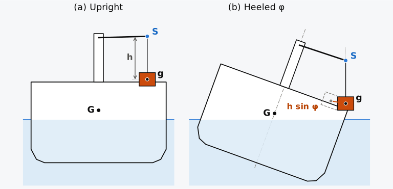
Figure 5.4 A load hanging from a crane at S, its centre of gravity g a distance h below S: (a) upright; (b) heeled, with the load as if fixed to the ship dashed. Schematic.
In practice this result is used as a rise of G. The moment a load that was resting on the deck is lifted clear of it, G rises by
where is now the height of the point of suspension above the load’s centre of gravity as it lay on the deck, and GM falls by . The rise is immediate and does not depend on how high the load is then hoisted, since hoisting only shortens the rope while the point of suspension stays where it is; it is undone the moment the load is set down again. Loads in a cargo hold that are stowed hanging from hooks, as sides of meat once were, act at their hooks: the metacentric height of a ship so loaded is less than with the cargo stowed on the floor of the hold3.
5.2.2 Lifting with the ship’s own crane
When the load is lifted from the quay instead of from the deck, it is a mass added to the ship at the point of suspension, which is usually high and well outboard, and it has two effects. The added mass raises KG, with its height taken at the point of suspension, and its transverse moment moves G off the centreline, so the ship lists while the load hangs over the side. The list follows from , with the GM of the ship as it is during the lift. It is largest when the load is at its greatest outreach, and it changes as the crane slews inboard and the load is landed. For ships engaged in lifting, the IS Code recommends that the hook load be taken, as here, at the point where it is applied to the lifting appliance, with that point’s distance from the centreline and height above the baseline4.
Example 5.2. A lift from the quay. The Series 60 ship, in its departure condition (7707 t, KG = 5.887 m, GM = 0.659 m), lies starboard side to a quay. Take G on the centreline and the liquids in the tanks as fixed. Its crane is to lift a 60 t piece of machinery from the quay with the crane head 19.5 m above the baseline and 12.0 m to starboard of the centreline, then slew inboard and land it on the hatch cover 10.5 m above the baseline and 5.0 m to starboard of the centreline. With 60 t more on board the ship floats at 6.408 m, where KM = 6.553 m. Find GM and the list (a) while the load hangs at its outreach and (b) after it is landed. (c) What list would be found by treating the hanging load as if it acted at its own centre of gravity, 2.0 m below the crane head?
For a heavy-lift ship, built to lift loads of hundreds or thousands of tonnes, the rise of G and the list are much larger, and the ship counters the listing moment by pumping water between wing tanks as the load moves. Water that is free to move in a tank has an effect of its own on stability.
5.3 Free surface effect
5.3.1 Liquid in a slack tank
A tank that is completely full, pressed up as it is said on board, behaves like solid cargo: the liquid cannot move, and its mass enters the weight table at the centre of the tank. Fresh water and ballast tanks can be pressed up, but an oil tank is not filled to the top, because the oil expands as it warms: a nominally full fuel tank of a merchant ship holds about 98 % of its capacity and keeps a small free surface3,6. A tank that is partly full is said to be slack, and its liquid has a free surface, which stays horizontal as the ship heels slowly. Its effect on stability is worked out for the liquid at rest in the heeled tank; the surging, or sloshing, of the liquid in a rolling ship is a separate matter, whose forces can be important for the strength of the tank5. When the box barge of Fig. 5.5 heels with a slack tank, a wedge of liquid runs from the high side of the tank to the low side, and the centre of gravity of the liquid moves from b to b′.
The geometry is that of Chapter 4, where two such wedges, between the upright and the heeled waterlines, gave the movement of the centre of buoyancy. The argument holds here, with the tank in place of the hull and the free surface in place of the waterplane. The two wedges have equal volumes, so the new surface passes through the centroid of the old surface, and for a small heel the moment of the transferred wedge is , where is the second moment of area of the free surface about the longitudinal axis through its own centroid. The centre of gravity of the liquid, of volume , therefore moves parallel to the surface through
The vertical through b′ meets the middle line of the tank at a point , a height above b, which is the metacentre of the liquid. If the liquid were solid, its weight would act through b at every small angle; free to move, it acts along the vertical through b′, which passes through , as if it were a solid weight hanging from . For this reason is called the virtual centre of gravity of the liquid7.
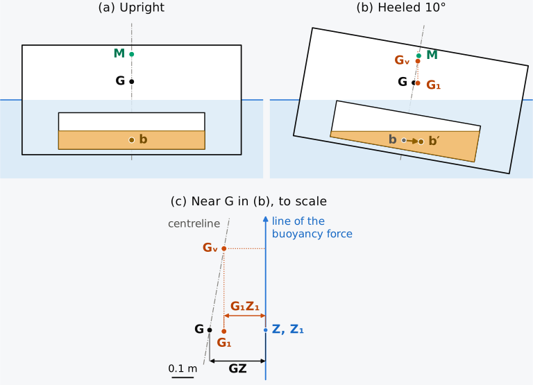
Figure 5.5 The free surface in a heeled tank: a box barge 60 m × 12 m at a draught of 3 m, with a tank 20 m × 8 m × 2 m half full of sea water, to scale; (a) upright, (b) heeled 10°, with the movement of G, and with it the height of above G, drawn three times larger, and (c) the region near G in (b).
Now apply the rule for a moved mass, Eq. (5.1), to the ship. The liquid has mass , where is its density, so G moves parallel to bb′ through
The weight of the ship now acts down the vertical through G₁ instead of through G, and that vertical meets the centreline at a point above G (Fig. 5.5(b)), at a height above it for small angles. The righting lever is measured from the line of the weight, so it is G₁Z₁ instead of GZ (Fig. 5.5(c)), and for small angles M sin φ instead of GM sin φ: the ship behaves as if its centre of gravity had risen to . This virtual rise of G, or free surface correction, is
with the density of the water the ship floats in, since . Equation (5.5) also follows directly from the hanging load. Freeing a liquid that was frozen7 acts on the ship as if its weight were lifted from b up to , as a load lifted clear of the deck comes to act at the crane head. With the mass and , Eq. (5.4) gives . The product , with in t/m³ and in m⁴, is a moment of mass in t·m, and is called the free surface moment of the tank. The metacentric height found with all liquids treated as fixed is called the solid GM. The metacentric height that governs the ship with its slack tanks, the fluid GM, is the solid GM less the sum of the corrections of every slack tank ,
and adding this sum to KG gives the fluid KG2,3. The water that the engineers of the Eastland let into its ballast tanks on the high side as the ship listed (Chapter 4) formed a free surface in each tank that it partly filled, and each such tank counts in this sum. For a rectangular free surface of length and breadth ,
Animation 5.1 shows the barge of Fig. 5.5 heeled slowly to 25° and back, with the liquid level at every angle and the righting lever traced twice, once with the liquid frozen and once with it free. The gap between the two curves is the loss of lever, and at small angles it is sin φ.
Animation 5.1 The box barge of Fig. 5.5 heeled from upright to 25° and back. Above, the section to scale: the liquid keeps a level surface, its centre of gravity moves across the tank, and G moves parallel to it (drawn three times larger than it is). Below, the righting lever against the heel, with the liquid frozen (the wall-sided formula) and with it free, computed exactly from the movement of the liquid. No sound; 11 s.
Predict 5.2. The tank of Fig. 5.5, 20 m long and 8 m wide, is half full of sea water. To reduce its free surface correction, one proposal is a longitudinal bulkhead on the centreline of the tank, and another is two transverse bulkheads that divide it into three tanks of equal length. Before reading on, say which reduces the correction more, and by how much.
Example 5.3. The slack tank of a box barge. A box barge 60 m long, 12 m wide and 6 m deep floats at a draught of 3 m in sea water. It displaces 2214 t and has GM = 1.50 m. A tank 20 m long, 8 m wide and 2 m deep on its centreline, with its bottom 0.3 m above the keel, is half full of sea water. Find the free surface moment, the virtual rise of G and the fluid GM. Repeat the calculation if the tank is divided by longitudinal bulkheads into two, and into three, tanks of equal breadth, and if it is divided instead by a transverse bulkhead at mid-length.
5.3.2 Factors governing the free surface effect
Predict 5.3. The tank of Example 5.3 is now a quarter full instead of half full, 82 t of water instead of 164 t, and the barge is loaded so that it still displaces 2214 t. Before reading on, say whether the virtual rise of G is halved, unchanged or something else.
As you have seen, the volume of the liquid does not enter the correction, as long as the free surface keeps its shape when the filling changes. In a tank with vertical sides it does: a film of liquid across the bottom has the same free surface moment as a tank nearly full, so long as the surface reaches neither the top nor the bottom of the tank as the ship heels. In a tank with sloping sides, such as a wing tank or a peak tank shaped by the hull, the breadth of the surface changes with the filling, and so does , which is then taken at the filling considered. The height of the tank in the ship does not enter the correction. A slack tank gives the same free surface correction in the double bottom as on an upper deck, and so does a tank off the centreline, since is taken about the surface’s own centroid. What remains is the density of the liquid relative to the water the ship floats in, and the shape of the free surface, which enters through .
Historical note: free water and the inclining experiment
Because goes with the cube of the breadth, the breadth of a free surface matters most, and the free surface is reduced by dividing it (Fig. 5.6). Take a rectangular free surface of length and breadth , divided by intact longitudinal bulkheads into compartments of equal breadth and the full length , with no liquid passing between them. Each compartment has a surface of its own, and their second moments, each about its own centroid, add up to
a quarter of the undivided value for one bulkhead and a ninth for two. A transverse bulkhead divides the length and leaves the sum of the second moments as it was. This is why the double-bottom tanks of a ship are divided at the centreline, and it is one reason why the cargo tanks of tankers have one or two longitudinal bulkheads6,8. The vehicle deck of the Herald had no such division.
The factor holds for this rectangular case only. For a surface of any other shape, or a division into unequal parts, the correction is found as in Eq. (5.6). Each isolated compartment counts with the density of its liquid times the second moment of its own surface about that surface’s centroid, at the filling considered, and the sum is divided by the displacement mass. A circular free surface of radius , divided by a bulkhead along a diameter, keeps of its undivided second moment , not a quarter. Each semicircle has a second moment of about the bulkhead. Its centroid lies from the bulkhead, and by the parallel-axis theorem of Chapter 2 its second moment about the centroid is smaller by its area times the square of that distance.
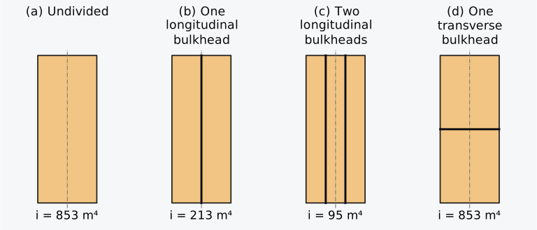
Figure 5.6 Dividing the free surface: a tank 20 m long and 8 m wide in plan, undivided, with one and two longitudinal bulkheads, and with one transverse bulkhead.
The rule also works in reverse. If the centreline division of a rectangular slack tank gives way, the two surfaces become a single surface and the free surface moment of the tank is multiplied by four. A failed division is therefore one of the recognized causes of a rise of G2, and barges have capsized from water in a double-hull space, especially when its centreline division had failed3. Tanks joined below their liquid level act in this way even when nothing has failed. In a U-shaped ballast tank, whose wings are joined through the double bottom, or in two wing tanks joined by an open pipe or valve, liquid runs from the high wing to the low wing as the ship heels, so that both surfaces stay on one level plane. The second moment of the joined surfaces is then taken about their common centroid, by the parallel-axis theorem of Chapter 2, instead of each about its own3. For a symmetric pair of wing tanks this centroid lies on the centreline, far from either surface, and the pair can have many times the free surface moment of the two tanks kept apart. For this reason the valves between such tanks are kept closed except when they are needed9.
A wash bulkhead, or swash bulkhead, is a longitudinal division pierced so that liquid passes through it. Barrass and Derrett count such bulkheads as dividing the surface, noting that the divisions need not be fully watertight and may have openings2. This can hold only in a quick roll, when the openings check the flow from side to side; in a slow, steady heel, such as a list, the liquid passes through the openings and both sides keep one level, as in tanks joined below their liquid level.
5.3.3 Free surface moments of a loading condition
A ship has many tanks with different liquids in them, and the correction for the ship is the sum of the corrections of all its slack tanks, as in Eq. (5.6). The tanks of the Series 60 ship that hold its fuel oil, diesel oil, lubricating oil and fresh water are given in Table 5.1, with their capacities, their contents and the free surface moment of each, and are drawn in plan in Fig. 5.7. The four oil tanks are in the double bottom. Their sides are vertical, so the free surface of each does not change with the filling. The fresh water is in the aft peak, a tank whose sides are the shell of the ship, and its free surface changes with the filling. Computed from the hull, its second moment is 262.0 m⁴ with the 110 t of the departure condition in it, only 3.4 m⁴ with the 11 t left on arrival, when the water lies in the narrow bottom of the peak, and at most 328.7 m⁴, at 98 % full, above which the tank counts as full, as described below.
A free surface whose breadth varies is integrated like a waterplane, with the transverse second moment of Eq. (2.13) taken over the half-breadths of the surface. The peak’s surface is symmetric, so its centroid lies on the centreline, the axis of that second moment. At the departure level, 7.687 m above the baseline, the half-breadths of the peak’s surface at stations 1.5 m apart, from the AP to the bulkhead at 9.0 m, are 1.771, 2.392, 2.913, 3.391, 3.830, 4.252 and 4.650 m. Multiplied by Simpson’s multipliers 1, 4, 2, 4, 2, 4, 1, their cubes sum to 786.11 m³, and
Because the half-breadth enters cubed, the wider forward half of the surface, with 60 % of its area, gives 77 % of .
Table 5.1 The tanks for the consumable liquids of the Series 60 ship (illustrative rectangular double-bottom tanks). , , : length, breadth and depth of a rectangular tank, whose free surface moment (FSM) is while it is slack and below 98 % full; the FSM of the aft peak is computed from the hull. Capacity at 100 % full; DB 3 is tank 3 of the double bottom, under hold 4.
| Tank | FO3P | FO3S | DO | LO | FW |
|---|---|---|---|---|---|
| Position | DB 3, port | DB 3, starboard | DB 5, centre | DB 4 | aft peak |
| Liquid | fuel oil | fuel oil | diesel oil | lubricating oil | fresh water |
| (t/m³) | 0.98 | 0.98 | 0.85 | 0.90 | 1.00 |
| (m) | 23.2 | 23.2 | 7.4 | 2.5 | – |
| (m) | 6.9 | 6.9 | 6.05 | 4.8 | – |
| (m) | 1.22 | 1.22 | 1.0 | 1.2 | – |
| Capacity (t) | 191.4 | 191.4 | 38.1 | 13.0 | 129.8 |
| Departure | |||||
| Contents (t) | 190 | 175 | 35 | 12 | 110 |
| Filling | 99 % | 91 % | 92 % | 93 % | 85 % |
| FSM (t·m) | 0 | 622.4 | 116.1 | 20.7 | 262.0 |
| Arrival | |||||
| Contents (t) | 19 | 18 | 4 | 12 | 11 |
| Filling | 10 % | 9 % | 10.5 % | 93 % | 8.5 % |
| FSM (t·m) | 622.4 | 622.4 | 116.1 | 20.7 | 3.4 |
| Largest FSM (t·m) | 622.4 | 622.4 | 116.1 | 20.7 | 328.7 |

Figure 5.7 The tanks of Table 5.1 in plan, on the outline of the Series 60 hull.
The free surface correction changes through the voyage. Tanks that were full become slack, and a tank shaped by the hull changes its surface as it empties, while the falling displacement makes each free surface moment count for more. For this reason the IS Code does not base the correction for consumables on how full each tank happens to be. It assumes that at least one pair of tanks, or one centreline tank, of each liquid has a free surface whatever its actual filling, and takes for it the largest free surface moment over the tank’s range of filling, because a free surface appears as soon as the ship starts to use the tank. For tanks whose contents are set, such as cargo and ballast tanks, the correction is taken for the actual filling. The Code counts a tank at 98 % of its capacity or more as full, with no correction, except a nominally full cargo tank, which it corrects as if it were 98 % full4.
Example 5.4. The fluid GM of the two loading conditions. The Series 60 ship displaces 7707 t with a solid GM of 0.659 m at departure, and 7236 t with a solid GM of 0.368 m on arrival. Find the free surface correction and the fluid GM in each condition, first with the actual contents of the tanks of Table 5.1, and then under the IS Code’s assumption for consumable liquids.
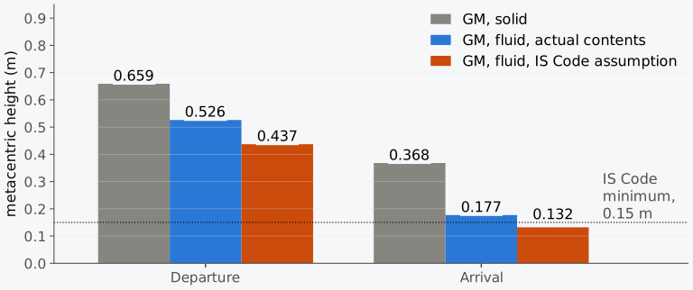
Figure 5.8 The solid and fluid GM of the Series 60 ship in the departure and arrival conditions, the fluid GM with the actual contents of the tanks and under the IS Code’s assumption for consumables.
The fluid GM is also the metacentric height with which a list is found, , and a free surface makes every list larger2. In Example 5.2 the lift from the quay lists the Series 60 ship 9.4° with its liquids treated as fixed; with the free surface moments of its departure condition counted, the list grows to 12.2°, with no change in any weight.
5.3.4 Large angles of heel, and tanks nearly full or empty
The free surface correction was derived for a small heel, with the surface clear of the top and bottom of the tank. At a finite angle, as long as the surface is clear, the liquid’s centre of gravity moves along a curve rather than a straight line. For a tank with vertical sides, the horizontal distance that it moves beyond its frozen position is , where the last factor is that of the wall-sided formula of Chapter 4 and comes, as there, from the vertical sides. The lever lost is then
where is that horizontal movement, measured in the earth’s frame; for small angles it reduces to sin φ. Once the surface reaches the top of the tank, or the bottom, the wedge that can move is cut off. The movement of the liquid then grows more slowly, and some degrees later it falls below the small-angle rule. For a rectangular tank of depth and breadth filled to a fraction of its depth, the surface reaches the top when
so the surface of a shallow, wide tank, or of a tank nearly full or nearly empty, meets the top or the bottom within a few degrees, while that of a deep tank half full stays clear to 30° and more. Figure 5.9 shows the ratio of the exact moment of the liquid to for rectangular tanks of three proportions, against the heel for a half-full tank and against the filling at 5° of heel. A half-full tank with = 0.2 reaches its top at 11.3°. At 12° its moment is still 1.7 % above , and it falls below near 13°.
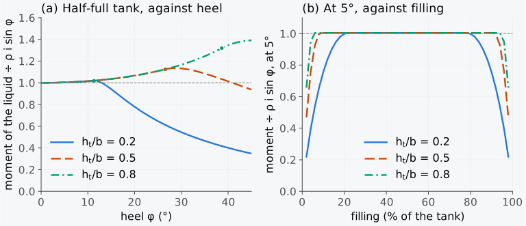
Figure 5.9 The moment of the liquid in a rectangular tank divided by : (a) a half-full tank against heel, for three depth-to-breadth ratios, with dots where the surface reaches the top; (b) the three tanks at 5° against the filling.
In Explorer 5.1 you can heel a rectangular tank of any proportions and filling, and watch the liquid, its centre of gravity and the lever lost, against the small-angle rule.
These effects are treated in stability information in one of two ways, and the IS Code allows either, provided that one method is used throughout a ship’s booklet. The correction to the initial metacentric height is normally made with taken at zero heel. The curve of righting levers is corrected either from the actual moment of the liquid at each angle, computed from the geometry of the tank as in Fig. 5.9, or from the zero-heel modified at each angle4. For wide double-bottom tanks that are nearly full, the first way gives a much smaller loss of lever than the small-angle correction beyond a few degrees, because the surface meets the tank top almost at once.
The Code also lets very small tanks be left out of the correction. The test is made at a heel of 30°: a tank whose free surface moment there, divided by the ship’s smallest service displacement mass, is less than 0.01 m need not be counted. That displacement is taken at the minimum mean service draught, with no cargo, 10 % of the stores and the minimum water ballast, if any is required4. The moment at 30° is the mass of the liquid times the horizontal distance its centre of gravity has moved beyond its frozen position, the numerator of Eq. (5.9), and for a tank of variable filling it is taken at the filling that makes it largest. For a rectangular tank it cannot exceed , its value while the surface is clear. The zero-heel moment is therefore a conservative screen: a tank that passes with it passes the test, but a tank that fails with it may still pass.
The Series 60 ship is taken here to need no water ballast in that condition. With no cargo, the crew and a tenth of the stores and consumables, its smallest service displacement mass is about 2924 t. Any ballast that it did need would raise this displacement and lower every ratio in the test, so the value without ballast is the stricter. The lubricating oil tank of Table 5.1 passes even the screen, since 20.7 t·m gives 0.007 m. The diesel oil tank fails the screen, at 0.040 m. Its moment at 30°, largest when the tank is half full, is 26.2 t·m, or 0.009 m, so it passes the test. The fuel tanks, at 150.1 t·m each (0.051 m), and the aft peak, at 59.3 t·m (0.020 m), do not. With the two small tanks left out, the free surface moments under the Code’s assumption fall to t·m. On arrival this gives m and m, which only just meets the minimum of 0.15 m, against the 0.132 m of Example 5.4 with every tank counted. Whether the ship meets this minimum-GM criterion on arrival without ballast depends on these two small tanks. The other applicable stability criteria must still be checked.
5.3.5 Water on the vehicle deck of the Herald of Free Enterprise
Now that we can calculate the free surface correction, we can apply it to the Herald of Free Enterprise. Water on a vehicle deck is a liquid with a free surface. In this illustration it extends across the whole breadth of a flat deck, and we hold the displacement at its departure value to isolate the free surface effect. At that fixed displacement the depth of the layer does not enter the initial correction. For a deck 22.7 m wide, each metre of its length that is covered by water has a free surface with m⁴, and on a ship of displacement mass 8874 t, the Herald’s at departure1, each metre adds m to the virtual rise of G. Against the length of deck covered (Fig. 5.10), the rise reaches the ship’s whole metacentric height, 2.09 m, when 18.6 m of the deck is covered, less than a sixth of the ship’s length, and 20 m of deck gives 2.25 m.
This virtual rise belongs to the upright ship, and it holds only while the water lies across the whole breadth of the deck. As the ship heels, the surface of the layer meets the deck on the high side when reaches twice the depth of the layer divided by the breadth of the deck, which is Eq. (5.10) with the deck as the bottom of the tank and the depth of the layer in place of . For a layer 5 cm deep this happens at about a quarter of a degree, and for a layer 0.5 m deep at 2.5°. Beyond that angle the water lies as a wedge on the low side, its free surface narrows, and the ship can come to rest at an angle of loll. A thin layer gives only a small angle, while a large quantity of water, still spread across much of the deck at larger angles, takes the ship much further over. The quantity of water therefore determines how far a ship that is unstable upright goes over, and on the Herald water kept coming in through the open doorway.
Predict 5.4. Suppose the water on the Herald’s deck was much deeper than 5 cm by the time the ship lurched (the report does not say how deep it was). Does that change the virtual rise of G calculated above?
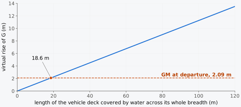
Figure 5.10 The virtual rise of G from water lying across a deck 22.7 m wide, on a ship of displacement mass 8874 t, against the length of deck covered; dashed, the Herald’s metacentric height at departure.
In this way a ship with 2.09 m of metacentric height could lose all of it within minutes, and the court used the words “free surface instability” for what happened1. By the calculation above, water across the whole breadth of more than about 19 m of the deck would make the fluid GM negative, and the court’s words describe a ship that had become unstable upright. In the report’s account it lurched over and then “became stable again at a large angle of loll”1: with the water collected in the port wing of the deck, the ship had both a raised G and an off-centre mass, and it settled at an angle instead of returning upright. The flooding that continued through the open doorway took the ship the rest of the way.
5.3.6 Reducing the free surface effect
A ship cannot avoid slack tanks: fuel and water are used, ballast is taken in and discharged, and liquid cargo is loaded and pumped out. A ship’s officer can keep their effect known and small. The number of slack tanks is kept small, as the IS Code recommends, and a filled swimming pool is counted among them4. One tank of each liquid is used at a time, and the others are kept full or empty, since an empty tank has no free surface either. A tank that is nearly full may be topped up, within its filling limits. Pressing a tank up removes its free surface, but a fuel tank is not pressed up, because the oil needs room to expand. At 98 % of its capacity or more the IS Code counts a tank as nominally full and, unless it is a cargo tank, omits its correction4. For consumable liquids the Code still assumes that at least one pair of tanks, or one centreline tank, of each liquid has a free surface, taken in the tanks where its effect is greatest4. Divided and narrow tanks are preferred for anything that must be slack, and the loss is worked out before a wide tank is used.
A transfer of liquid is calculated before it starts. It changes which tanks are slack, moves G and changes the list, and both tanks have a free surface while the pump runs. The IS Code recommends that the most onerous stage of ballasting be assessed, and allows the correction for a liquid transfer to be taken at the fillings of each stage4. For a low, wide double-bottom tank filled from empty, that stage comes early in the filling, when the whole free surface already acts and little weight has gone in3. A ship at an angle of loll needs particular care. Slack tanks already on board are topped up first, which removes their free surfaces2. When an empty double-bottom tank is then filled on the low side, as in Sec. 4.9.3, the first water increases the heel, because it adds weight on that side and creates a free surface, until enough has gone in for its low weight to bring G down2. Tanks of small area are therefore filled first, each in turn.
Example 5.5. Filling the starboard fuel tank. The Series 60 ship in its departure condition displaces 7707 t with KG = 5.887 m, a solid GM of 0.659 m and a fluid GM of 0.526 m. Its slack tanks have a total free surface moment of 1021.2 t·m, of which 622.4 t·m belongs to the starboard fuel tank FO3S, holding 175 t of its 191.4 t capacity. Find the fluid GM if 15.1 t more fuel is taken into that tank before sailing. The tank then holds 190.1 t, 99.3 % of its capacity, which the IS Code counts as full, with no free surface correction. The added fuel forms a layer about 0.1 m deep near the top of the tank, with its centre 1.16 m above the baseline, and at 7722 t the ship’s KM is 6.548 m.
Some slack tanks are carried on purpose. A ship that must take a listing moment while it works, from a heavy lift or from vehicles moving on and off, may carry anti-heeling tanks: a pair of wing tanks between which water is pumped to cancel the moment as it arises. The listing moment of a lift is matched by a mass of water times the distance between the tanks. An anti-rolling tank is kept partly full so that its water, running across the ship out of time with the roll, works against it. Its free surface is counted in the stability calculation, as two tanks if the connection between its wings is closed and as a single tank if it is open3. The IS Code names both among the ballast tanks whose most onerous stage of filling or discharge should be assessed4. In exceptional cases it allows a slack tank to be used to reduce an excessive GM, with due regard to sloshing4. It also recommends that a ship that counter-ballasts during a lift be able to withstand the sudden loss of the hook load, when the ballast moment is left unopposed4.
5.4 Shifting and liquefying bulk cargo
A solid cargo stowed in bulk, such as grain, ore, coal or sand, is neither fixed nor liquid. It stays where it is until the ship rolls past the angle at which the heap can stand, the angle of repose of the material. The angle of repose is 20° to 22° for most grains, and from 34° upwards for ores6.
The angle of repose also determines how far the cargo moves. Suppose the cargo has been trimmed to a level surface and the ship rolls to an angle larger than the angle of repose . Up to the surface turns with the ship; beyond it the cargo slides until its surface is no steeper than . As the ship rolls back, the cargo does not move until the slope of its surface again exceeds the angle of repose6, so the roll leaves the surface tilted in the ship by . The cargo has then moved as a liquid would at a heel , with the difference that it stays there. In a hold with vertical sides, of length and breadth , a wedge of section has moved from the high side to the low side, its centre crossing the hold through and rising through . With , the second moment of area of the cargo surface, the moments of the shift across the ship and upwards are
where is the mass of the wedge, and are the distances through which its centre moves, and is the density of the cargo in bulk. Divided by , the first moves G across and lists the ship, and the second raises G and reduces the GM with which the list is found.
A cargo trimmed level has the whole of its angle of repose in hand before it slides, while a heap left at its natural slope can slide at the first heel. The International Code for the Safe Carriage of Grain in Bulk, the International Grain Code, therefore generally requires the free grain surface in a partly filled compartment to be level. An exception introduced in January 2026 permits untrimmed ends in a qualifying specially suitable compartment filled at least to the bottom of its hatch end beams; the surface within the hatch opening must still be level. The exception has its own assumed-shift calculation and is not permission to leave an ordinary hold untrimmed10. The Code also limits the list that an assumed shift of the grain may cause10. The model of the shift is statical; in a ship rolling quickly, the accelerations can start a shift at smaller angles, more readily in cargo stowed above G, as in a ’tween deck, than below it, in the hold3,6. The list that a shifted cargo produces persists, since the cargo does not move back until the ship heels far enough the other way. With a list, the ship reaches larger angles on the low side as it rolls, and a roll that passes the angle at which the cargo slides again shifts it further; progressive shifts of this sort have capsized ships3. Moving loads, liquid and solid alike, are a case of positive feedback: the heel moves the load, and the moved load increases the heel6.
Example 5.6. A shift of grain in hold 4. The Series 60 ship, loaded with grain, displaces 7707 t, with = 0.894 m and BM = 3.129 m. Hold 4, 24.0 m long, is partly filled with grain of density 0.556 t/m³ and angle of repose 21°, trimmed level; at the level of the grain the hold has vertical sides 16.256 m apart. In heavy weather a single large roll takes the ship to 30° to starboard, and its rolls then die down. Find the tilt of the grain surface in the ship after the roll, the movement of G, and the list by the wall-sided formula.
Some cargoes behave as liquids outright. Fish carried loose in a hold are one example, and the stability calculation treats such a hold as a slack tank6. The IS Code asks that portable divisions be properly installed in the holds before fish are carried in bulk4. Fine-grained mineral cargoes such as nickel ore and iron ore fines can liquefy in a seaway if they are loaded wetter than the transportable moisture limit, the highest moisture content at which the cargo may be carried, set for each cargo from tests3. The cargo then endangers the ship in two ways at once. It flows to one side and lists the ship, as a shifted cargo does, and its surface becomes the free surface of a liquid with the cargo’s own density, as for fish in bulk6. For a ship of displacement mass 7707 t with such a cargo lying across a hold 24.0 m long and 16.256 m wide, the virtual rise of G is 1.115 m for each tonne per cubic metre of the cargo’s density, and any such cargo denser than about 0.80 t/m³ would take away more than the whole of a metacentric height of 0.894 m. The International Maritime Solid Bulk Cargoes (IMSBC) Code classes such cargoes as Group A and requires the moisture content to be tested and certified below the transportable moisture limit before loading11.
5.5 Stability of a loading condition
5.5.1 Steps of the calculation
We can now complete the stability calculation for a loading condition. A ship’s officer makes it before every departure, and the designer makes it for every condition in the stability booklet, in five steps.
- The weight table: every item on board with its mass and the position of its centre of gravity. The sums give , , and KG. A load that hangs from a crane enters at its point of suspension.
- The hydrostatic table at that displacement: the draught, KB and BM, and so KM; or KM read directly from the metacentric diagram, using data appropriate to the ship’s trim.
- The solid metacentric height, .
- The free surface moments of the slack tanks, from the ship’s tank tables, with the rules’ assumptions about which tanks are slack. Their sum divided by is the free surface correction, which gives the fluid GM. Added to KG, the correction gives the fluid KG. Before comparing it with a limiting KG curve, check the convention in the approved stability information: some limits already include a prescribed free surface allowance, which must not be counted a second time.
- The checks: the fluid GM against the required minimum; against zero, for the list, which is found with the fluid GM; and against , for the trim. The righting lever at large angles, corrected for free surfaces, is checked as well.
The departure condition of the Series 60 ship is worked in this form in Table 5.2, with a column for the free surface moment of each slack tank.
Table 5.2 The departure condition of the Series 60 ship, with the free surface moments of its slack tanks.
| Item | (t) | (m) | (t·m) | FSM (t·m) |
|---|---|---|---|---|
| Lightship | 2850 | 6.85 | 19,522.5 | |
| Crew, effects, stores and provisions | 35 | 11.83 | 414.0 | |
| Fuel oil, DB tank 3, port (full) | 190 | 0.62 | 117.8 | 0 |
| Fuel oil, DB tank 3, starboard (slack) | 175 | 0.57 | 99.8 | 622.4 |
| Diesel oil (slack) | 35 | 0.44 | 15.4 | 116.1 |
| Lubricating oil (slack) | 12 | 0.56 | 6.7 | 20.7 |
| Fresh water (slack) | 110 | 6.22 | 684.2 | 262.0 |
| Cargo, holds 1 to 5 | 4300 | 5.699 | 24,507.1 | |
| Total | 7707 | 45,367.5 | 1021.2 | |
| KG = 45,367.5/7707 | 5.887 m | |||
| KM at 7707 t, 6.367 m draught | 6.546 m | |||
| GM, solid | 0.659 m | |||
| Free surface correction, 1021.2/7707 | 0.133 m | |||
| KG, fluid | 6.020 m | |||
| GM, fluid | 0.526 m |
The crew and effects and the stores and provisions are combined in one line, and the cargo of the five holds in another. Their moments are the sums of the separate items of the weight table, Table 3.1, and their heights are those moments divided by the masses, so the two rows do not multiply out at the decimals printed (4300 × 5.699 = 24,505.7 t·m against the sum 24,507.1 t·m; the difference is the rounding of the height, 0.3 mm).
5.5.2 Loading calculator (Calculator 5.1)
Calculator 5.1 goes through the departure and arrival conditions of the Series 60 ship step by step, as in Table 5.2, using its tanks and the hydrostatic curves of the hull. It also accepts a loading of your own: the items of a weight table, the slack tanks with their lengths, breadths, densities and the number of parts of equal breadth into which bulkheads divide them, and any suspended load. It reports the solid and fluid GM, the list, and the tank whose free surface costs the most.
Each expression of this chapter holds only under the condition for which it was derived: a hanging load must hang freely, and the free surface correction assumes a small heel. The cases of loading are collected in Table 5.3, each with its effect on G and GM, its expression and the condition to check before the expression is used.
Table 5.3 Moved, added, hanging and liquid loads: the effect on G and GM, the expression to use and its condition.
| Load | Effect on G and GM | Expression and condition |
|---|---|---|
| A mass moved up or down | G moves parallel to the movement; GM falls by GG′ if the mass is raised | , Eq. (5.1); KM is unchanged, as nothing is added or removed |
| A mass moved across the ship | G moves off the centreline, and the ship lists | Eq. (5.1), then at small angles, Eq. (4.16) |
| A mass added or removed | G moves towards a mass added and away from a mass removed; GM changes with KG and KM | KG′ by Eq. (5.2), the change of GM by Eq. (5.3), with KM at the new draught and a discharged mass entered as negative |
| A load hanging from a crane | Acts at its point of suspension: G rises when the load leaves the deck, and GM falls by as much | , Eq. (5.4), while the load hangs freely; lifted from a quay, a mass added at the point of suspension |
| Liquid in a slack tank | G rises virtually to , and GM falls to the fluid GM | , Eq. (5.5), summed over the slack tanks by Eq. (5.6), with at the actual filling; for a small heel, with the surface clear of the top and bottom of the tank. Independent of the amount of liquid while the surface keeps its shape, as with vertical sides |
| A slack tank divided by longitudinal bulkheads | The correction is the sum of those of the parts; for a rectangular surface in parts of equal breadth it is divided by | Eq. (5.6), with the of each part about its own centroid; Eq. (5.8) for the rectangular case, with intact bulkheads, parts of breadth and the same length, and no connection between them below the liquid level |
5.6 Free surfaces and moving loads in industry today
This section describes practice in 2026 and is revised at each release of the book.
Free surfaces in the stability information. Every loading condition in a ship’s stability booklet is corrected for free surfaces as described in Sec. 5.3, following Part B, 3.1, of the IS Code4. For nominally full cargo tanks the correction to GM is based on the second moment of the surface at 5° of heel (3.1.2), the only case in which the zero-heel value is not used.
Tank tables and loading computers. The tanks of a real ship are seldom rectangular, and the second moment of a free surface changes with the filling as the surface meets the sloping sides of a wing tank or the top of a double-bottom tank. In loading computers, the moment of the liquid is computed from the tank’s geometry for a series of fillings at a small angle of heel, typically 5°, and stored as a table, which the program looks up for the actual filling of each tank3. The IMO Guidelines for the approval of stability instruments, MSC.1/Circ.1229, name the free surface moment of each compartment against the level of its contents among the data such an instrument holds, and the free surface correction among its results12. A program that computes from a model of the hull should give both within 2 % of the approved stability information12. IACS UR L5, the classification societies’ unified requirement for such software, asks for the GM corrected for free surfaces within 1 % of the approved value or 5 cm, whichever is greater13.
Water on vehicle decks. Water can also collect on a vehicle deck from the ship’s own fire-fighting system, and in large quantities it could cause a serious loss of stability. The International Convention for the Safety of Life at Sea, 1974 (SOLAS), therefore requires a ship built since 1 January 2010 whose vehicle or ro-ro spaces are protected by a fixed pressure water-spraying system to drain that water. A passenger ship drains its spaces above the bulkhead deck through scuppers that discharge directly overboard, and on a ro-ro passenger ship their valves are kept open at sea. A cargo ship needs drainage sized for at least 125 % of the combined capacity of the spraying pumps and the required fire hoses; where that is not possible, the weight and free surface of the water are taken into account in the ship’s stability information14.
Lifting. The IS Code’s provisions for lifting (Part B, 2.9) apply to ships built from 1 January 2020, and they take effect when the heeling moment of the lift exceeds a threshold set by the ship’s displacement, GM, freeboard and breadth (2.9.1.2). Besides the treatment of the hook load and of counter-ballasting described earlier in this chapter, they limit the equilibrium heel during the lift to what the lifting gear is designed for, and they call for a residual freeboard4.
Cargoes that shift or liquefy. The IMSBC Code is mandatory under SOLAS chapter VI. It requires the shipper of a Group A cargo to declare its moisture content and its transportable moisture limit, both determined by test, before loading11. Amendment 08-25 may be applied voluntarily from January 2026 and becomes mandatory in January 2027; it updates the cargo schedules and related requirements15. The carriage of grain in bulk is governed by the International Grain Code.
What has changed. The free surface correction is unchanged since Attwood’s day, but it is now computed from the real geometry of each tank at each filling, from tables held by the loading computer3, and the IS Code fixes the assumed fillings, the 98 % limit and the method for the curve of righting levers4.
5.7 From moving weights to trim
So far we have dealt with heel. A mass moved along the ship, or loaded forward or aft of the centre of flotation, changes the trim and with it the draughts forward and aft, which are what the master reads and what the load line surveyor inspects. In Chapter 6 we will find the draughts of a loaded ship from the longitudinal metacentre and the moment to change trim one centimetre. The free surface of a long tank acts on trim as it does on heel, through the longitudinal second moment of its surface, and we will see in Chapter 6 when that matters. In Chapter 7, KB, KM, the longitudinal metacentre and the moment to change trim are gathered into the hydrostatic curves that stability booklets carry.
Summary
A mass moved on board moves the centre of gravity of the ship parallel to it, through the mass times its travel divided by the displacement mass. Moved upwards, it reduces GM; moved across or along the ship, it makes the ship list or trim. A mass loaded or discharged changes KG by its moment about the keel and KM through the change of draught, and whether GM rises or falls depends on both; on the Series 60 ship at its loaded draughts a load leaves GM unchanged when it is placed a little above G. A load hanging freely from a crane acts at its point of suspension. Lifting a load off the deck therefore raises G at once, by the mass times the height of the suspension point above the load’s centre of gravity divided by the displacement mass, and a load lifted from a quay is a mass added at the crane head. This equivalence assumes a settled load and negligible accelerations.
A liquid with a free surface shifts as the ship heels, and at small angles it acts as if its weight hung from its virtual centre of gravity, a height above its own. The effect is a virtual rise of G equal to the free surface moment, the liquid’s density times the second moment of its surface about its longitudinal centroidal axis, divided by the displacement mass. For a small heel, with the surface clear of the top and bottom of the tank, the position of the tank does not enter, and the breadth of the surface enters cubed. While the surface keeps its shape as the filling changes, as in a tank with vertical sides, the amount of liquid does not enter either; in a tank with sloping sides the second moment is taken at the actual filling. Intact longitudinal bulkheads that divide a rectangular surface into parts of equal breadth and the same length divide the effect by . For any other division the free surface moments of the separate parts are added, each about its own centroid, and tanks joined below their liquid level act as one surface.
The fluid GM is the solid GM less the sum of the corrections of all slack tanks, and it is the fluid GM that is compared with the rules and with which a list is found. In a tank with vertical sides, the liquid moves a little more at larger angles than the small-angle rule says, while its surface is clear. Once the surface meets the top or bottom of the tank, the movement grows more slowly and later falls below the rule, within a few degrees in a tank nearly full or nearly empty; the curve of righting levers is then corrected from the actual movement of the liquid. Water across a wide deck is the extreme case: at the Herald of Free Enterprise’s departure displacement, the simplified calculation for water covering less than 20 m of deck across its whole breadth gives a virtual rise of G larger than its initial metacentric height.
A level bulk cargo rolled slowly beyond its angle of repose is left with its surface tilted in the ship by the excess of the roll over that angle, as a liquid would be at that heel, and it stays there until the ship heels far enough the other way; a larger roll to the low side can shift it further, while a cargo trimmed level has the whole of its angle of repose in hand. On board, these results are applied as working rules:
- enter a hanging load at its point of suspension, and check the list and GM at the greatest outreach before the hook is made fast;
- keep slack tanks few and the valves between them closed, top up tanks that are nearly full, and count a free surface in every tank below 98 % full and in at least one tank or pair of each consumable;
- calculate a transfer of liquid before starting it, with the free surface in both tanks while it runs;
- read the free surface moment of each tank at its actual filling from the tank tables, and check the fluid GM at every stage of the voyage that changes it, not at departure only;
- trim and load bulk cargo according to its applicable code and approved loading information, allowing for the shifts or liquefaction that the cargo may undergo.
Notes on the data
The Herald of Free Enterprise. The particulars, the loading condition at departure (displacement mass 8874 t, 2.09 m, trim 0.75 m by the head) and the account of the capsize are from the report of the Formal Investigation, cited by paragraph1. That condition is the lower of the two that the Department calculated for the court; with the upper condition of the report1, 9250 t and 2.04 m, water across the deck would use up the metacentric height over 18.9 m of its length, against 18.6 m. The calculation in Sec. 5.3.5 is a simplified illustration, not a reconstruction of the accident. It treats water lying across the full moulded breadth of the vehicle deck, 22.7 m, over a stated length, with the ship’s departure displacement, and takes no account of the vehicles standing on the deck, of the sheer and camber of the deck, of the water’s own mass or of the trim. The report does not estimate the quantity of water on the deck at the moment of the lurch.
The tanks of Table 5.1. The Series 60 ship has no published general arrangement. The double-bottom tanks that hold the oils of the weight table, Table 3.1, are given dimensions here that suit the masses and centroids already in that table: each tank’s capacity exceeds its departure contents, its centre lies close to where the departure and arrival conditions place the liquid, and the plan positions are consistent with a double bottom under the holds. These dimensions are illustrative. The fresh water is in the aft peak, taken as the moulded hull of Chapter 1 between the AP and the peak bulkhead 9.0 m forward of it, and between flats 3.0 m and 8.0 m above the baseline, the tank of Table 3.1. With the 110 t of the departure condition the peak is 85 % full, and the centre of the water is 5.74 m forward of the AP and 6.22 m above the baseline, as in Table 3.1; with the 11 t of the arrival condition it is 6.70 m and 3.64 m. The free surface moments of the peak are computed from the hull at each filling, in scripts/ch05_data.py, and the seven half-breadths of Sec. 5.3.3 are read from the hull at the departure level. The fuel oil has the density of Example 3.3, 0.98 t/m³. The fuel tanks of Chapter 3 are the double bottom under hold 4, 44 m to 68 m forward of the AP, bounded by the hull between the keel and the tank top at 1.2 m, 196.8 m³ on each side. Table 5.1 replaces each by a rectangular tank 23.2 m long, 6.9 m wide and 1.22 m deep, 195.3 m³. The rectangle is deeper than the double bottom because its depth is set by the capacity: 1.2 m deep, it would hold 188.3 t, less than the 190 t of FO3P at departure. At 1.22 m, FO3P with its 190 t, and FO3S with 190.1 t in Example 5.5, are 99.3 % full, which the IS Code counts as full. The centroids of the masses are those of Table 3.1. On arrival the fuel’s transverse centres, 2.93 m and 2.94 m from the centreline, lie 0.5 m inboard of the centres of the tank outlines drawn in Fig. 5.7; the transverse moments in this chapter use the centres of Table 3.1. The smallest service displacement mass used for the small-tank test, 2924 t, is the lightship with the crew and a tenth of the stores and consumables of Table 3.1, with no water ballast.
Examples 5.1, 5.2 and 5.5. KM at the new displacement is read from the hull’s hydrostatic data (data/ch05.json), and KG from the printed values of the weight table, with its rounding. The crane of Example 5.2 and the load’s height in part (c) are illustrative.
Grain in hold 4 (Example 5.6 and Exercise 5.15). In the grain condition, the ship loads a parcel of 3996.2 t of grain of density 0.556 t/m³, a stowage factor of 1.80 m³/t. It fills holds 2, 3 and 5, and the rest of it lies in hold 4, 44.0 m to 68.0 m forward of the AP; hold 1 is empty. Water ballast, 303.8 t, is pressed full in the fore peak tank, the hull forward of the collision bulkhead at 114 m and below 8 m, and in the double bottom under holds 2 and 5. The grain and the ballast together weigh as much as the 4300 t of cargo of the departure condition, so that the ship displaces 7707 t. Computed from the hull between the tank top, 1.2 m above the baseline, and the deck, the level surface of the grain in hold 4 lies 5.76 m above the baseline. The GM corrected for free surfaces, 0.894 m, is that of this condition, computed on the whole hull with the trim free and with the free surfaces of the consumables as the IS Code assumes; BM at 7707 t is read from the hydrostatic data (data/ch05.json). At the level of the grain the hold is 16.256 m wide over most of its length and at least 16.16 m at its ends, and the second moment of its actual surface is 8581.0 m⁴, 0.1 % less than with vertical sides 16.256 m apart. The tilted surfaces of Example 5.6 stay between 3.6 m and 8.0 m above the baseline, clear of the tank top and the deck. At 3.6 m, the lowest point they reach, the hold is still at least 15.88 m wide, so that its sides are close to vertical over the whole range that the surfaces sweep. The angle of repose, 21°, lies within the range for most grains6, and the rolls are illustrative.
Figure 5.9 and Explorer 5.1. The movement of the liquid in a rectangular tank at finite heel is computed exactly from the geometry (the polygon of the liquid below a level surface, with its area fixed), in scripts/ch05_data.py and in the explorer’s own code, which interactive/test_ch05_widgets.cjs checks against the Python values.
The box barge of Example 5.3 and Animation 5.1. The barge is 60 m × 12 m × 6 m at a draught of 3 m with KG = 4.0 m, and the tank, 20 m × 8 m × 2 m, has its bottom 0.3 m above the keel. The animation’s frozen lever is the wall-sided formula, which holds until the deck edge immerses at 26.6°, beyond the animation’s range of 25°.
Exercises
Under each exercise, “Show answers” opens its short answers and “Show full solution” its worked solution.
5.1 A ship of 9000 t has GM = 0.80 m. A mass of 200 t is moved 6.0 m straight down. Find the new GM. The mass is then moved 4.0 m across the ship: find the list.
5.2 A ship of 7000 t has KG = 7.20 m and KM = 7.90 m. How much ballast must be added with its centre 0.80 m above the keel to bring GM to 1.00 m, if KM is taken as unchanged?
5.3 A box barge 60 m long and 12 m wide floats at a draught of 3.0 m in sea water, with KG = 4.0 m and KM = 5.5 m. It is to take 100 t. Find its draught and KM with the mass aboard, the change of KM, and the height at which the 100 t leaves GM unchanged.
5.4 A ship of 5000 t has GM = 0.70 m. Its crane, with its head 16.0 m above the keel, lifts 40 t of cargo that was resting on the deck on the centreline with its centre of gravity 8.0 m above the keel, and then slews until its head is 10.0 m outboard. Find the fall of GM when the load leaves the deck, and the list when the load hangs 10.0 m outboard.
5.5 A ship of 6500 t, KM = 7.60 m and KG = 6.90 m, lifts 80 t from the quay with a derrick whose head is 20.0 m above the keel and 9.0 m outboard. Find GM and the list while the load hangs, and after it is landed on deck 10.0 m above the keel and 6.0 m from the centreline. Take KM as unchanged.
5.6 A ship of 12,000 t has a rectangular slack tank 24 m long and 10 m wide containing fuel oil of density 0.95 t/m³. Find the free surface correction with the tank undivided, and with one and with two longitudinal bulkheads that divide it into parts of equal breadth.
5.7 A lighter in the form of a box is 30 m long and 6 m wide and floats at a draught of 1.2 m. Its metacentric height when empty is 1.8 m. Two transverse bulkheads are built 3 m from each end. Show that a small quantity of water in the central compartment makes the lighter unstable upright, and explain its initial tendency and how an equilibrium at an angle might be reached. Neglect the added water’s small effect on draught and solid KG. Adapted from Attwood7.
5.8 A rectangular tank 15 m long, 9 m wide and 1.5 m deep in a ship of 8000 t contains sea water. Find the free surface correction when it is half full and when it is a quarter full, and the heel at which the surface first reaches the bottom of the tank in each case.
5.9 A ship of 9000 t has KM = 8.00 m and KG = 7.40 m. A double-bottom tank 16 m long, 12 m wide and 1.4 m deep, with its bottom on the keel, is full of sea water. Half of it is pumped out. Find the rise of G from the mass removed, the free surface correction, and the fluid GM, taking KM as unchanged.
5.10 A fishing vessel of 400 t has GM = 0.55 m. A rectangular hold 6.0 m long and 5.0 m wide holds fish in bulk, which behave as a liquid of density 0.90 t/m³. Find the fluid GM, and the fluid GM if two longitudinal portable divisions divide the hold into three parts of equal breadth.
5.11 A ship’s smallest service displacement mass is 2924 t. A rectangular lubricating oil tank is 4.0 m long and 3.6 m wide and holds oil of density 0.90 t/m³. Using the zero-heel free surface moment as a screen, show that the tank is small enough to be left out of the free surface correction under the IS Code’s test for small tanks. What is the widest tank of that length and liquid that passes the screen?
5.12 The vehicle deck of a ferry of 8874 t is 22.7 m wide, and the ferry’s metacentric height is 2.09 m. Find the length of deck that must be covered by water for the virtual rise of G to equal 2.09 m, and the heel at which a layer 0.5 m deep across the deck would first leave the deck dry on the high side. Then find the virtual rise if the deck of this ferry were 15 m wide, with the covered length unchanged.
5.13 On arrival the Series 60 ship displaces 7236 t, with KG = 6.129 m and KM = 6.497 m. Under the IS Code’s assumption for consumables, with every tank counted, the free surface moments total 1710.3 t·m (Table 5.1), so the fluid GM is 0.132 m, below the 0.15 m that the IS Code requires4. (a) Find the fluid GM if 150 t of sea water is taken into an empty double-bottom ballast tank and pressed up, with its centre 0.62 m above the baseline; at 7386 t, KM is 6.511 m. (b) Find the fluid GM if the 150 t is instead left slack in a double-bottom tank 20 m long, 8 m wide and 1.25 m deep, with its bottom on the keel, so that its centre is 0.46 m above the baseline. (c) Find the fluid GM by the IS Code’s method when the first 10 t has run into this tank from empty, and the heel at which that layer of water leaves the high side of the tank bottom dry; at 7246 t, KM is 6.498 m.
5.14 A box barge displacing 2214 t has a tank 20 m long, 8 m wide and 2 m deep, half full of sea water. Find the heel at which the surface reaches the top of the tank, and the lever lost at 10° of heel by the small-angle rule.
5.15 The Series 60 ship, loaded with grain, displaces 7707 t, with = 0.894 m and BM = 3.129 m. Hold 4, 24.0 m long, has vertical sides 16.256 m apart at the level of its grain, which has a density of 0.556 t/m³ and an angle of repose of 21° and is trimmed level. A longitudinal division on the centreline of the hold reaches 2.03 m above and below the grain surface. The ship rolls to 30° to starboard. Find the mass of grain that moves, how far its centre of gravity moves across the ship and upwards, the movement of G across the ship, and the list by the wall-sided formula.
5.16 A container ship of 30,000 t at a berth has a pair of anti-heeling wing tanks whose centres are 24 m apart, each 12 m long and 4 m wide. A crane lift places 40 t 20 m from the centreline. (a) How much water must be moved from one tank to the other to keep the ship upright? (b) What is the free surface correction of the pair while both are slack? (c) What is it if the valve between the two tanks is left open?
5.17 A ship of 10,000 t has KG = 8.00 m and KM = 8.20 m, so GM = 0.20 m, and is to take 500 t of deck cargo with its centre 12.0 m above the keel. Find GM with the cargo aboard. How much ballast with its centre 1.0 m above the keel must be taken first for the fluid GM to be at least 0.30 m with the cargo aboard and the ballast tanks pressed full? Take KM as unchanged.
5.18 A load of 20 t hangs from a point 3.0 m above its centre of gravity in a ship of 4000 t. By how much does GM fall, and what free surface moment in a tank would reduce GM by that amount?
5.19 The Series 60 ship in its departure condition displaces 7707 t, with KG = 5.887 m and G 0.007 m to port of the centreline, and the slack tanks have free surface moments totalling 1021.2 t·m. Lying starboard side to a quay, the ship lifts 60 t from it with its crane head 19.5 m above the baseline and 12.0 m to starboard of the centreline; at 7767 t, KM is 6.553 m. Find the list while the load hangs, first with the liquids treated as fixed and then with their free surfaces counted.
Symbols introduced in this chapter
| Symbol | Meaning | Unit |
|---|---|---|
| , | breadth and length of a tank, hold or free surface | m |
| , | a mass moved on board, and the distance through which it is moved | t, m |
| , | distances through which the centre of a shifted wedge of bulk cargo moves across the ship and upwards | m |
| b, b′ | centre of gravity of the liquid in a tank, upright and heeled | – |
| virtual centre of gravity of the liquid in a slack tank, a height above b | – | |
| filling of a tank as a fraction of its depth | – | |
| FSM, | free surface moment of a tank | t·m |
| GG′, | movement of G when a mass is moved, and when the liquid of a slack tank shifts | m |
| virtual rise of G: the free surface correction, or the rise from a suspended load | m | |
| , | fluid metacentric height and fluid KG, corrected for free surfaces | m |
| height of the point of suspension above the centre of gravity of a hanging load | m | |
| depth of a rectangular tank | m | |
| second moment of a free surface about the longitudinal axis through its centroid | m⁴ | |
| number of compartments of equal breadth into which longitudinal bulkheads divide a rectangular free surface | – | |
| S, g | point of suspension and centre of gravity of a hanging load | – |
| , | volume and density of the liquid in a tank | m³, t/m³ |
| , | mass added to the ship and the height of its centre above the baseline | t, m |
| half-breadth of a free surface at a station, the -coordinate of its edge | m | |
| height at which an added mass leaves GM unchanged | m | |
| Z, Z₁ | feet of the perpendiculars from G and G₁ to the line of the buoyancy force | – |
| tilt of the surface of a bulk cargo in the ship after a shift | ° | |
| angle of repose of a bulk cargo | ° | |
| horizontal movement of the liquid’s centre of gravity beyond its frozen position | m | |
| density of a bulk cargo | t/m³ | |
| angle to which the ship rolls | ° |
Corrections
Corrections to version 1.0, released on 3 November 2026, with their dates.
- 3 November 2026. Sec. 5.6 and the reference list cite SOLAS in its consolidated edition of 2024, in place of that of 2020.
- 5 November 2026. The prologue and Sec. 5.3.5 cite paragraph 9.3 of the report of the Formal Investigation, which gives the account of the flooding and the capsize, in place of paragraph 9.2, and the prologue cites paragraphs 1.1 and 1.2 for the departure and the deaths.
- 5 November 2026. The prologue and the Notes on the data say that the metacentric height of 2.09 m at departure belongs to the lower of the Department’s two loading conditions, 8874 t, and give the upper, 9250 t with a metacentric height of 2.04 m, which the court thought the more probable; the water came in over the spade, not over a sill. Sec. 5.3.5 states the result of its illustration as a length of flooded deck.
- 5 November 2026. Table 5.1 gives the filling of the diesel oil tank on arrival as 10.5 %, in place of 10 %, and Sec. 5.3.3 says at what filling the aft peak has its largest free surface moment.
- 5 November 2026. Sec. 5.6 gives the tolerance of IACS UR L5 on GM corrected for free surfaces, 1 % of the approved value or 5 cm, whichever is greater, in a sentence of its own, apart from the tolerances of MSC.1/Circ.1229.
References
- Department of Transport. (1987). mv Herald of Free Enterprise: Report of Court No. 8074, Formal Investigation (Sheen, J., Wreck Commissioner). Her Majesty’s Stationery Office. Retrieved October 10, 2026, from https://assets.publishing.service.gov.uk/media/54c1704ce5274a15b6000025/FormalInvestigation_HeraldofFreeEnterprise-MSA1894.pdf Cited: ↑ paras 1.1 and 1.2 · ↑ para. 4.1 · ↑ para. 8.3 · ↑ para. 8.5 · ↑ para. 10.1 · ↑ paras 7.3 and 8.3 · ↑ paras 4.4, 5.3 and 9.3 · ↑ para. 9.3 · ↑ para. 4.1 · ↑ para. 8.3 · ↑ para. 9.3 · ↑ para. 9.3 · ↑ · ↑ para. 8.5
- Barrass, C. B., & Derrett, D. R. (2006). Ship stability for masters and mates (6th ed.). Butterworth-Heinemann. Cited: ↑ pp. 15–18 · ↑ p. 121 · ↑ pp. 51–53, 202–205 · ↑ p. 121 · ↑ p. 211 · ↑ p. 209 · ↑ p. 53 · ↑ p. 54
- Moore, C. S. (2010). Intact stability (J. R. Paulling, Ed.; Principles of Naval Architecture Series). Society of Naval Architects and Marine Engineers. Cited: ↑ p. 40 · ↑ p. 38 · ↑ p. 38 · ↑ p. 30 · ↑ p. 31 · ↑ p. 36 · ↑ pp. 36–37 · ↑ p. 39 · ↑ pp. 17 and 37 · ↑ p. 37 · ↑ p. 37 · ↑ p. 37 · ↑ pp. 33–34 · ↑ pp. 33–34
- IMO. (2020). International Code on Intact Stability, 2008 (2020 ed.). International Maritime Organization. (Includes the Explanatory Notes, MSC.1/Circ.1281.) Cited: ↑ Part B, 3.4.2.6.1 · ↑ Part B, 3.4.1.2 and 3.4.2.3 · ↑ Part B, 2.9.2.1 · ↑ Part B, 3.1.2 to 3.1.4 · ↑ Part A, 2.2.4 · ↑ Part B, 3.1.8, 3.1.9 and 3.1.11 · ↑ Part B, 3.1.12 · ↑ Part B, 5.1.5 · ↑ Part B, 3.1.2 · ↑ Part B, 3.1.4 · ↑ Part B, 3.1.5 and 3.1.6 · ↑ Part B, 3.1.5 · ↑ Part B, 5.1.6 · ↑ Part B, 2.9.5 · ↑ Part B, 2.1.2.5 and 5.2.4 · ↑ · ↑ Part B, 2.9.3 · ↑ Part B, 3.1 · ↑ Part A, 2.2.4 · ↑ Part B, 3.1.5 and 3.1.8
- Tupper, E. C. (2013). Introduction to naval architecture (5th ed.). Butterworth-Heinemann. Cited: ↑ p. 69 · ↑ p. 69
- Biran, A., & López-Pulido, R. (2014). Ship hydrostatics and stability (2nd ed.). Butterworth-Heinemann. Cited: ↑ pp. 143–144 · ↑ pp. 144–147 · ↑ p. 148 · ↑ p. 148 · ↑ p. 148 · ↑ pp. 149–150 · ↑ p. 147 · ↑ p. 148 · ↑ p. 148
- Attwood, E. L. (1899). Text-book of theoretical naval architecture. Longmans, Green, and Co. (Public domain.) Cited: ↑ pp. 125–126 · ↑ p. 126 · ↑ p. 124 · ↑ pp. 126–127 · ↑ p. 127 · ↑ ch. III, Ex. 31
- Kemp, J. F., & Young, P. (2001). Ship stability: Notes and examples (3rd ed., rev. C. B. Barrass). Butterworth-Heinemann. Cited: ↑ pp. 119–121
- Nickum, G. C. (1988). Subdivision and damage stability. In E. V. Lewis (Ed.), Principles of naval architecture: Vol. I. Stability and strength (2nd rev., ch. III). Society of Naval Architects and Marine Engineers. Cited: ↑ p. 175
- IMO. (1991). International Code for the Safe Carriage of Grain in Bulk (Resolution MSC.23(59), adopted 23 May 1991; paragraphs numbered as amended by Resolution MSC.552(108), adopted 23 May 2024, in force 1 January 2026). International Maritime Organization. Retrieved October 13, 2026, from https://wwwcdn.imo.org/localresources/en/KnowledgeCentre/IndexofIMOResolutions/MSCResolutions/MSC.23(59).pdf. Amendments read in International Code for the Safe Carriage of Grain in Bulk (1991 edition): Supplement (January 2026), retrieved October 19, 2026, from https://wwwcdn.imo.org/localresources/en/publications/Documents/Supplements/English/2Q240E_supplement_January2026_EBK.pdf Cited: ↑ A 2.8, A 10.4 and A 10.7 · ↑ A 7.1
- IMO. (2008). International Maritime Solid Bulk Cargoes (IMSBC) Code (Resolution MSC.268(85), as amended). International Maritime Organization. Cited: ↑ sections 1.7, 4 and 7 · ↑ sections 1.7, 4 and 7
- IMO. (2007). Guidelines for the approval of stability instruments (MSC.1/Circ.1229, 11 January 2007). International Maritime Organization. Cited: ↑ annex, paras 4.2.3 and 4.3.2 · ↑ annex, para. 4.6
- IACS. (2020). Computer software for onboard stability calculations (UR L5, Rev. 4, June 2020). International Association of Classification Societies. Retrieved October 9, 2026, from https://iacs.s3.af-south-1.amazonaws.com/wp-content/uploads/2022/02/17101147/ur-l5rev4.pdf Cited: ↑ Section 5.2, Table 1 and Note 2
- IMO. (2024). SOLAS: Consolidated edition 2024 (Sales No. IH110E). International Maritime Organization. Cited: ↑ reg. II-2/20.6.1.4
- IMO. (2025). Amendments to the International Maritime Solid Bulk Cargoes Code (IMSBC Code) (Resolution MSC.575(110), adopted 26 June 2025; Amendment 08-25). Retrieved November 2, 2026, from https://wwwcdn.imo.org/localresources/en/KnowledgeCentre/IndexofIMOResolutions/MSCResolutions/MSC.575(110).pdf Cited: ↑