The Code of Safety for Dynamically Supported Craft, adopted by IMO in 1977 as Resolution A.373(X), defined such a craft as one whose weight was carried in one mode of operation to a significant extent by forces other than hydrostatic forces, or whose Froude number , with the waterline length, was 0.9 or more4. For the Wigley hull of 100 m this meant 28.2 m/s, about twice the speed of Eq. (14.1). According to Moore2, the code of 1977 gave only very general guidance on stability in high-speed operation. The first High-Speed Craft Code followed in 1994, and it was revised in 2000 to reflect the experience of a fleet that was growing fast2.
Figures and tables have more room in landscape.
Chapter 14: Stability of multihulls, submersibles, high-speed craft and offshore units
Version 1.0 · last revised 5 November 2026 · corrections
Prologue: the Ocean Ranger on the Grand Banks
When the Ocean Ranger entered service in June 1976 it was the largest semi-submersible drilling rig in the world, a unit of eight columns on two lower hulls1. The rig was 408 ft (124.4 m) long and had been built in Hiroshima by Mitsubishi Heavy Industries1. In February 1982 it was moored in about 260 ft (79 m) of water on the Grand Banks, some 166 nautical miles (307 km) east of St. John’s, Newfoundland1. The rig floated at 80 ft (24.4 m), its maximum draught1. Its ballast was controlled from a room in the after starboard centre column. The room had four portlights fitted with deadlights1, and its deck lay about 28 ft (8.5 m) above the water1. The four corner columns held the anchor chain lockers, whose openings lay about 71.5 ft (21.8 m) above the water1.
On 14 February a forecast warned of significant waves of 20 ft (6.1 m) and of westerly winds of 70 knots (36 m/s), gusting to 90 knots, by midnight1. At 1847 the rig reported that the drill pipe had been sheared and the riser disconnected1. At 2044, in seas of 50 ft (15 m) and more and winds of 90 to 100 knots, it reported that a wave had broken a window of the ballast control room1. Around 2100 voices on the radio spoke of electric shocks in the panel and of valves opening on their own1, and at 2145 the rig reported that everything was cleaned up and normal1.
At 0052 on 15 February the rig broadcast a distress message reporting a severe list1. The senior drilling foreman aboard told the shore superintendent that it was listing by the bow, by eight to ten degrees as the superintendent understood him1. At 0105, as the master of the standby vessel Seaforth Highlander recalled it, the rig reported a list to port and that all countermeasures were ineffective1. A telex at 0109 described a severe list of about 10 to 15 degrees, to the port side1. At 0110 the rig asked the SEDCO 706 to relay a mayday, adding that if no reply came to later calls, the crew would have taken to the lifeboats1. A lifeboat was seen alongside the Seaforth Highlander, where it capsized1. At about 0300 the rig capsized and sank. All 84 people on board were lost, and the wreck lies upside down in about 260 ft (79 m) of water1.
The National Transportation Safety Board of the United States found that sea water entering through a broken portlight had disabled the ballast control console, and that the crew could not then work the ballast valves by hand. Water passed into the forward ballast tanks, by transfer from other tanks or otherwise, and the unit took a list of 10° to 15° in the direction of the severe wind and waves. The flooding of the chain lockers in its forward columns brought on the capsize1. Because its waterplane is made up of the sections of its columns, a unit of this form may be least stable about an axis that is neither fore and aft nor athwartships. Its stability must also resist wind moments that grow with the height and shape of every member above the sea. In this chapter we will see how the stability of multihulls, submarines and submersibles, high-speed craft and offshore units differs from that of a conventional ship, and how it is judged under the rules made for each of them. We will return to the Ocean Ranger in Sec. 14.5.8.
In this chapter
By the end of this chapter you will be able to:
- find the metacentric height of a multihull and follow its curve of righting levers;
- find the trim and heel of a submerged submarine and compensate a change of load;
- find the GM of a semi-submersible at its transit and operating draughts;
- judge an offshore unit against the intact criteria of the 2009 MODU Code;
- estimate the foilborne GM of a hydrofoil and explain the instability of an idealized single air cushion.
What it assumes. You need BM = and the wall-sided formula, Eqs. (4.3) and (4.13). The parallel-axis theorem of Chapter 2 is used for the hulls of a multihull. The wind heeling moments and area criteria build on Secs. 9.2.1 and 9.3.1.
A first reading. Sections 14.1 to 14.3, 14.4.1 to 14.4.4, 14.5, 14.6.3 and 14.6.4 carry the main thread. The dive, the surfaced boat and passenger submersibles (Secs. 14.4.5 to 14.4.7), and the requirements of the HSC Code and planing craft (Secs. 14.6.1 and 14.6.2), can wait for a second reading; the hazards of high-speed craft concern their motions more than their hydrostatics. Table 14.3, at the end of Sec. 14.6, compares the main craft of the chapter and can be read with the main thread.
14.1 Stability when the waterplane changes
14.1.1 The waterplane and the support of a craft
The ships of the earlier chapters float on their buoyancy, apart from the blocks and the ground of Chapter 13, and their initial stability comes from the waterplane. When a ship heels, a wedge of the hull emerges on one side and a wedge immerses on the other, and the centre of buoyancy moves towards the low side. For a small heel this movement is fixed by the second moment of the waterplane, through BM = , Eq. (4.3). The metacentric height GM = KB + BM − KG then combines this form stability of the waterplane with the height of G, which is set by the loading. A ship of ordinary form keeps its waterplane while it heels through small angles, and the methods of Chapters 4 and 8 rely on this.
The craft of this chapter differ from such a ship in their waterplane or in their support. A catamaran divides its waterplane between two hulls set apart, which multiplies . A small-waterplane-area twin hull (SWATH) and a semi-submersible keep most of their volume deep under water and pierce the surface only with slender struts or columns, and a submerged submarine has no waterplane at all. Planing craft, hydrofoils and air-cushion vehicles are carried at speed by hydrodynamic lift or by air pressure rather than by buoyancy, and their means of stability then differ from craft to craft2.
Of the five craft of Fig. 14.1, all of 2050 t and drawn to one scale, the catamaran has the waterplane area of the monohull and with it an equal TPC. Its metacentric radius is eight times larger, since its area lies far from the centreline. The SWATH and the semi-submersible keep only about a third and a fifth of that area, and their draught is sensitive to weight. Their BM comes from a small area set far from the centreline. The submarine, once submerged, has neither waterplane area nor BM.
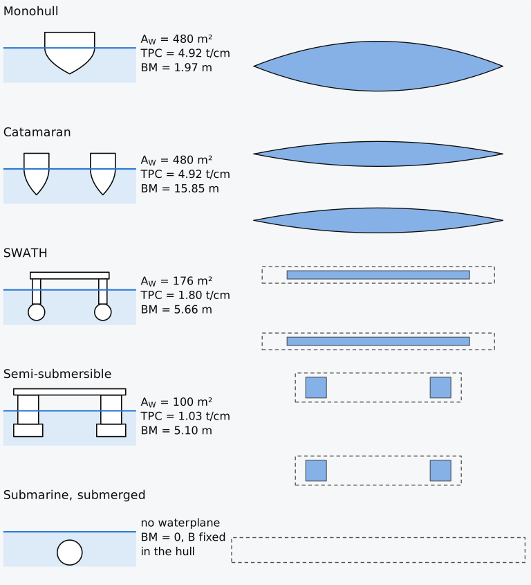
Figure 14.1 Sections seen from aft (left) and waterplanes in plan (right) of five illustrative craft of 2000 m³ (2050 t in sea water), drawn to one scale. Waterplanes shaded; hulls below the water dashed in plan.
14.1.2 The definition of a high-speed craft
In the International Code of Safety for High-Speed Craft, 2000 (2000 HSC Code), adopted by the International Maritime Organization (IMO) as Resolution MSC.97(73), a high-speed craft is a craft capable of a maximum speed , in metres per second, of at least
where is its volume of displacement at the design waterline in cubic metres3. Since 0.1667 is about 1/6, the speed of Eq. (14.1) is proportional to the square root of , a length of the craft. The definition amounts to a Froude number of at least = 1.18. The Wigley hull of the earlier chapters, 100 m long and 10 m wide at a draught of 6.25 m, with = 2777.8 m³, would need 13.88 m/s (27.0 knots) to count as a high-speed craft. The Code also defines the modes in which such a craft operates. In the displacement mode it is carried wholly or mainly by hydrostatic forces, in the non-displacement mode mainly by other forces, and in the transitional mode it passes between the two3.
Historical note: from dynamically supported craft to high-speed craft
14.2 Multihulls
14.2.1 The metacentric radius of separated hulls
Of the craft of this chapter, the multihull departs least from the ships of Chapters 4 and 8, since, in displacement mode, its waterplane is only divided between its hulls. Its waterplane consists of an area for each hull, and its second moment about the centreline is the sum of the second moments of the parts. By the parallel-axis theorem of Chapter 2, each part contributes its second moment about its own centreline and its area times the square of the distance of that centreline from the centreline of the craft,
The general results of hydrostatics hold for catamarans and trimarans as for single hulls5, and BM is divided by the total volume of displacement. Consider a catamaran of two equal hulls, or demihulls, whose centreplanes are a distance apart, the spread6. Each demihull has the waterplane area , the volume , the second moment about its own centreline and the metacentric radius . Equation (14.2) then gives , with , and
The first term is the metacentric radius of a demihull floating by itself, which is small for the slender hulls of most catamarans, and the second term grows with the square of the spread. For two box demihulls of breadth at the draught , and , which give
A box barge divided into two boxes of half its breadth, with their centreplanes one and a half barge breadths apart, keeps its displacement and draught but has seven times its metacentric radius5. In that barge the second moments of the two boxes about their own centrelines make up only 1/28 of the total, and without the parallel-axis term almost all of BM would be lost.
14.2.2 Metacentric height and rolling
With comparable loading and suitable hull spacing, a catamaran generally has a much larger metacentric height than a monohull of equal displacement7, and a GM above 10 m is usual in large catamarans7. A large GM makes the craft stiff in roll: by Eq. (4.10) the natural period of roll falls as if the effective radius of gyration is held fixed, and a stiff craft has a shorter natural roll period and, for a given roll amplitude, higher accelerations2. With its small ratio of length to overall breadth, a catamaran has natural periods of roll and pitch that lie close together. In oblique seas this gives a corkscrew motion that can cause serious motion sickness7.
14.2.3 The curve of righting levers of a catamaran
Up to moderate angles a catamaran of wall-sided demihulls behaves exactly like the wall-sided box of Sec. 4.7.2. Its twin waterplane is symmetric about the centreline, the wedge that emerges from the high hull equals the wedge that immerses in the low hull, and successive waterlines cross on the centreline. The righting lever then follows the wall-sided formula, Eq. (4.13), with the BM of Eq. (14.3):
where the heel φ is positive with the starboard side down, as throughout the earlier chapters. The formula holds only while every side that the water cuts is vertical. With the starboard hull going down, it fails at the first of two events: the outer bottom corner of the high (port) hull reaches the water, or the outer deck edge of the low (starboard) hull is immersed. For box demihulls of breadth and freeboard at the draught , with the waterline turning about the centreline, these events occur at
Only the smaller of the two angles marks a real event; beyond it the waterline no longer turns about the centreline, and the larger angle no longer gives the second event. A catamaran of shallow draught and generous freeboard lifts a hull first, and a catamaran of deep draught and low freeboard immerses a deck edge first.
Once the high hull begins to lift, the waterplane is lost on the high side, and its centroid, with the axis about which the waterline turns, moves towards the low hull. When the deck edge of the low hull is immersed first, the axis moves towards the rising hull7. With all the buoyancy in the low hull, the centre of buoyancy can move no further out than the outer side of that hull, and G often lies high. The lever peaks soon after a hull lifts or a deck edge immerses, and falls to zero at a moderate angle; the immersion of a downflooding point does not change the calculated curve for the assumed intact watertight hull, but limits its use in the criteria. Actual water ingress changes the loading and stability. Craft of large GM usually have the peak of their curve at relatively small angles2,7.
Example 14.1. The curve of righting levers of a box catamaran. A catamaran has two box demihulls, each 30 m long, 3.0 m wide and 4.0 m deep, with their centreplanes 9.0 m apart, and floats in sea water at a draught of 1.5 m with KG = 4.0 m. The cross structure that joins the hulls lies above their decks and gives no buoyancy. (a) Find BM and GM, and compare BM with that of a demihull floating by itself. (b) Find which event comes first as the craft heels, the lift of the high hull or the immersion of the deck edge of the low hull, the angle at which it occurs, and the righting lever there. (c) Computed on the hull at constant displacement, the curve has its largest lever, 3.393 m, at 20.4°; the high hull is clear of the water at 21.8°, the deck edge of the low hull reaches the water at 33.7°, and the lever vanishes at 64.7°. Interpret these results, and find the metacentric height of the craft when it floats upside down.
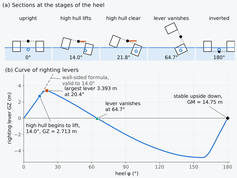
Figure 14.2 The twin-box catamaran of Example 14.1. (a) Sections seen from aft at the stages of the heel, to scale. (b) Curve of righting levers from upright to upside down, with the wall-sided formula dashed.
As can be seen from Fig. 14.2(b), the computed curve follows the wall-sided formula exactly up to 14.0°, while both hulls keep their vertical sides in the water. In Animation 14.1 the section and the curve are drawn together as the craft heels.
Animation 14.1 The twin-box catamaran of Example 14.1 heeled from upright to 72°, beyond the angle at which its lever vanishes. No sound; 16 s.
14.2.4 Deep demihulls
The catamaran of Example 14.1 floats on shallow boxes. A catamaran of deeper hulls, such as the Wigley hull of Chapter 1, has a draught that is large compared with its freeboard, and its deck edge is immersed long before a hull can lift.
Example 14.2. The spread of a Wigley catamaran. A catamaran is formed of two Wigley demihulls, each 100 m long, 10 m wide and 10 m deep, floating at their design draught of 6.25 m. Each demihull has a volume of displacement of 2777.78 m³, a waterplane area of 666.67 m², KB = 3.906 m and BM = 1.371 m. The craft has KG = 9.0 m, and its cross structure lies above the decks of the hulls. (a) Find the spread that gives GM = 15.0 m. (b) Estimate the angle at which the deck edge of the low hull reaches the water. (c) Computed on the hull at constant displacement, the curve of righting levers for this spread reaches 5.257 m at 26.6° and vanishes at 68.8°; the deck edge reaches the water at 15.6°, and the keel of the high hull would reach it only at 54.4°. Interpret these results.
14.2.5 Trimarans and sailing multihulls
A trimaran has a slender main hull and a smaller side hull on each side, called a float, sponson or ama. The side hulls provide stability while the main hull stays slender for low wave resistance. The stability of the craft is much like that of a catamaran, with more freedom in distributing the second moment of the waterplane between the hulls2. With side hulls of a sharp V form, the low side hull picks up buoyancy only from about 5° of heel7. A curve that is low and concave at the start can leave the craft lying heeled for long periods in a beam wind or sea, and once a side hull leaves the water the craft behaves like an asymmetric catamaran7. A fine main hull may have a GM of 2 to 3 m by itself. In the design of a trimaran of 102 m, side hulls were sized to raise it to between 6 and 8 m, and with them the roll stayed below 2° at almost every heading to the waves7.
A sailing catamaran heels little while both hulls are in the water, and its righting moment grows almost linearly with the heel. By the time the windward hull lifts, the righting moment is already close to its largest value, as in Example 14.1. A gust that exceeds it can overturn the craft within the few degrees between the lift of the hull and the peak of the curve. For vessels carrying passengers in the United States, a sailing catamaran is judged by the moment of its sails rather than by its curve of righting levers. Under section 171.057 of Title 46 of the Code of Federal Regulations (46 CFR 171.057), its displacement in kilograms, its spread in metres, its largest sail area in square metres and the height of the centre of effort of the sails above the deck in metres must satisfy
with = 4.88 kg/m² on protected waters and 7.32 kg/m² on partially protected or exposed waters8. The product grows with the spread, as the righting moment at the lift of a hull does.
14.2.6 Criteria for multihulls
The early peak of a catamaran’s curve does not suit the general criteria of the International Code on Intact Stability, 2008 (IS Code), which require the largest righting lever to occur at 25° of heel or more9. A catamaran whose curve peaks at 20° fails this criterion however large its GM. Where the criterion is not practicable, the Code allows alternative criteria of an equivalent level of safety, approved by the Administration9. Its Explanatory Notes suggest a maximum at 15° or more, with a least area up to it that Eq. (11.3) gives9. The Code gives no intact criteria written for multihulls10.
In the 2000 HSC Code a multihull is a craft whose rigid hull, at any trim or heel that it can normally reach, breaks the surface of the sea in more than one separate area3. The Code requires multihulls other than hydrofoils to meet the criteria of its Annex 7, monohulls those of its Annex 8 and hydrofoils those of Annex 6. Where an annex does not suit a craft, the Administration may accept other criteria of equivalent safety3. Within the Codes’ application, craft constructed on or after 1 January 1996 and before 1 July 2002 follow the 1994 HSC Code, adopted by Resolution MSC.36(63); those constructed on or after 1 July 2002 follow the 2000 Code9.
Under Annex 7 of the 2000 Code, the area under the curve of righting levers is taken up to an angle , the least of the downflooding angle, the angle of the largest lever and 30°. It must be at least 0.055 × 30°/ m·rad, and the largest lever must occur at 10° or more11. The steady wind lever of the annex is the moment of a pressure of 500(/26)² Pa on the lateral area above the waterline, divided by the displacement, with the speed in m/s of the worst intended wind. The heel under a gust, with 1.5 times that lever, is limited to 10° by the annex11. The greater heeling lever from passenger crowding or a high-speed turn is combined with the gust lever. Beyond the resulting heel , the residual area under the GZ curve, of the annex, must be at least 0.028 m·rad up to the angle of roll. In the absence of model tests or other data, the roll range is 15°, cut short at the downflooding angle if that comes first11. Craft built under the 1994 Code are judged by its own Annex 7, with a fixed wind pressure of 500 Pa and these area and angle requirements12.
The area required by Annex 7 grows as the angle of the largest lever falls, from 0.055 m·rad if the peak lies at 30° to 0.0809 m·rad for the peak of Example 14.1 at 20.4°. The catamaran of that example has 0.678 m·rad up to its peak. A multihull outside the HSC Code’s scope has no dedicated multihull criteria in the IS Code; an approved alternative may be needed where its general criteria do not suit the craft. The German flag administration, for example, accepts chapter 2.3 and Annex 7 of the 2000 HSC Code for such craft, since their intact stability depends little on their speed10.
14.2.7 Exploring a catamaran (Explorer 14.1)
In Explorer 14.1 you can change the spread, the breadth of the demihulls, the draught and KG of a catamaran of box demihulls 4.0 m deep. Its curve of righting levers, from upright to upside down, is computed by clipping the hull sections at the water at constant displacement. The curve is marked at the computed heels at which the high hull begins to lift and the deck edge of the low hull reaches the water, at the largest lever and at the angle at which the lever vanishes. The section is drawn at a heel that you choose. The demihulls are prismatic, and none of the values depends on their length. Aim for realistic values: a spread of two to four times the breadth of a demihull, a draught of a third to a half of the depth, and a KG near the height of the decks.
14.3 Small waterplane craft
A SWATH is a displacement catamaran whose buoyancy lies mostly in two deeply submerged lower hulls, joined to the deck by slender struts that pierce the surface. It gives up much of the stability of a catamaran for smaller motions in waves. Its small waterplane gives low wave drag and good seakeeping2, and it lengthens the natural period of heave7. The motions of a SWATH stay small while its natural periods of heave, pitch and roll lie well above the periods of the waves that it meets; long swells can still excite slow heave and pitch unless fins or other appendages damp the motion7. The intact stability of a SWATH is computed as for a ship and judged by the criteria for catamarans2,7.
Its TPC is small, and its draught changes much with weight: the SWATH of Fig. 14.1 sinks 1 cm for each 1.80 t, against 4.92 t for the monohull. Weight control is a main concern in its design (Sec. 7.5.2). Compared with a conventional ship, a SWATH has a smaller initial GM. The buoyancy lies deep and keeps KB low, while the deck must stand well clear of the waves and raises G7. Its BM may still be the larger, as in Fig. 14.1. At larger angles the struts, which often broaden just above the design waterline, and the watertight lower part of the deck structure immerse, and the curve rises faster. Beyond about 8°, for example, the righting lever of the SWATH Navatek 1 grows at a greater rate7.
The longitudinal metacentric height of a SWATH is of a similar size to its transverse, far smaller than in a monohull, and control surfaces can therefore stabilize heave and pitch as well as roll2. Under way, the flow over the lower hulls produces a bow-down moment that grows with the square of the speed, which fins at their sterns must balance, as on a submarine7.
14.4 Submarines and submersibles
14.4.1 The two states of a submarine
A submarine loses its waterplane altogether when it dives, and it operates in two states of equilibrium. On the surface it is a ship with little freeboard, kept upright by its waterplane and its low centre of gravity; submerged, it is a body wholly under water whose weight equals its buoyancy. The boat passes between the two with its main ballast tanks, which have vents at the top and flood openings at the bottom. To dive, the vents are opened and the sea enters through the flood openings as the air escapes; to surface, the tanks are blown with compressed air2. The submerged displacement is that of the whole envelope of the boat less its free-flooding spaces, which the sea fills and drains freely. For a rigid envelope its volume is fixed by the geometry, and its displaced mass varies with the density of the water2. On the surface the boat displaces less, and the difference, its reserve buoyancy, equals the water admitted to the main ballast tanks when it dives2. In diving trim its weights are adjusted until, with the main ballast tanks full, its weight equals its submerged displacement and its centre of gravity lies on the vertical through its centre of buoyancy2.
In these definitions the water of the main ballast tanks is counted as weight, by the method of added weight of Chapter 12. Counted by lost buoyancy, the boat would float in an unchanged position with another displacement, KB, KG and GM.
14.4.2 Stability of the submerged boat
A body wholly under water keeps its immersed volume as it inclines, and, as Sec. 4.4.3 showed, its centre of buoyancy B stays at a fixed point of the body2. The verticals through B at successive inclinations all pass through B itself, and the metacentre coincides with B. BM = vanishes as well, since there is no waterplane2. The metacentric height of the submerged boat is then the height of B above G, written GB and positive when G lies below B. It is the reverse of BG, the height of G above B, used for surface ships, and it is equal for every horizontal axis of inclination; hydrostatics provides no restoring moment in yaw2. Its righting lever is
for fixed centres with GB positive, largest at 90° and positive between 0° and 180°, apart from the movement of liquids and loose items2. The boat behaves as a pendulum of length GB hung from B2. Section 4.4.3 uses the same GB, the height of B above G, positive when G lies below B.
The longitudinal metacentric height, of the order of the length in a surface ship, has also fallen to GB. As a result, a trimming moment trims the boat by about the angle through which an equal heeling moment would heel it2. If a mass is moved a distance forward and to port, G moves by and , and the boat inclines until G lies again below B. The heel φ, positive with the starboard side down, and the trim angle θ, positive bow up, are given, for separate transverse and longitudinal shifts at unchanged height, by
where is the submerged displacement in tonnes. Since GB is a fraction of a metre, small shifts give large angles, and every change of weight is compensated at once. A torpedo that is fired, for example, is replaced immediately by an equal weight of water at its position2. Hydroplanes, the horizontal control surfaces of a submarine, add longitudinal stability only while the boat is under way2. Free surfaces act in both directions, and since many tanks are longer than they are wide, the longitudinal free surface effect may be the larger in a submerged boat2.
Example 14.3. A weight moved in a submarine. A double-hull submarine has a buoyant hull 60 m long, whose envelope, without its free-flooding spaces, has a volume of 2206.75 m³ with its centroid 3.372 m above the keel. Its main ballast tanks hold 487.98 m³. On the surface, with these tanks empty, it floats at a draught of 4.880 m with KB = 2.726 m and KG = 3.000 m, and its waterplane is 6.433 m wide and 60 m long. Submerged, with the tanks full, its centre of gravity lies 3.130 m above the keel. (a) Find the submerged displacement, the reserve buoyancy as a percentage of the surfaced volume of displacement, and GB. (b) Find the trim when a mass of 1.5 t is moved 30 m forward, and the heel when it is moved 3.0 m to starboard, with the boat submerged. (c) Find the trim caused by the move of 30 m when the boat is on the surface.
14.4.3 Stability in depth
The submerged boat is stable in heel and trim while G lies below B, but it has no waterplane to restore it in heave. In uniform, incompressible water, a rigid boat with weight equal to buoyancy is in neutral equilibrium at any depth, and a submarine must therefore control its depth actively (Sec. 3.1.4). Whether it drifts up or down depends on how its buoyancy changes with depth. Treated as an elastic body, a submersible compresses as it goes deeper in water that is effectively incompressible. It then loses buoyancy, sinks further and is unstable in depth13. Most submarines are unstable in depth in this way, because the loss of buoyancy by compression of the hull exceeds the gain from the slightly denser water at depth2. A very rigid hull is an exception: it compresses less than the water and is slightly stable in depth2. A boat can also rest on a layer of denser water if its weight lies between its displacements in the two waters2. A tank partly filled and open to the sea makes the instability worse, because the air in it expands and contracts with the depth2.
14.4.4 Compensation and the trim tanks
To hold depth without a sustained vertical control force, the boat’s weight must equal its submerged displacement, as in diving trim. Every change of the variable load of a submarine, the stores, people, weapons, water and fuel that come and go, is therefore compensated by adjusting its variable ballast. This is sea water in a forward and an after trim tank and in auxiliary tanks near amidships2. The fuel tanks are kept full by sea water as the oil is used, and consumption hardly changes the weight2. A mass added at forward of B is compensated by discharging from the forward and from the after trim tank, whose centroids lie and forward of B, being negative. The weight and the longitudinal moment are both restored when
the rule of the lever, by which the added mass is shared between the two tanks in inverse proportion to their distances from it.
The variable ballast must also follow the density of the sea, because the submerged displacement is fixed by the volume. If the water in the main ballast tanks takes the density of the water outside, the change of variable ballast is
where is the submerged volume, the volume of the main ballast tanks and the change of density2. The density of sea water ranges from about 1.019 to 1.030 t/m³, and an imbalance of 10 t between weight and buoyancy, less than half a per cent of the 2261.9 t of the boat of Example 14.3, is already unacceptable2.
Example 14.4. Compensating a store in a submarine. The submarine of Example 14.3, which displaces 2261.9 t submerged with GB = 0.242 m, takes on a store of 2.4 t at 15.0 m forward of B and 4.0 m above the keel. Its forward trim tank has its centroid 22.0 m forward of B and its after trim tank 20.0 m aft of B, both 1.4 m above the keel. Leave out the free surfaces of the trim tanks. (a) Find the water to be discharged from each trim tank to restore the weight and the trim. (b) Find the new GB. (c) Estimate the trim that would remain if the weight were compensated from an auxiliary tank longitudinally at B instead, retaining the original GB for this first estimate.
Beyond single changes such as this store, the variable ballast tanks must be large enough for every condition of the boat. Designers check them against its extreme loading conditions: heavy, light, heavy forward and heavy aft, in heavy and in light water2. The weight and moment of variable ballast that each condition requires are plotted with the equilibrium polygon, the envelope of the weights and moments that the tanks can give; each side of the polygon is the effect of filling one tank. A condition that falls outside the polygon calls for a change of the solid ballast, usually lead, or of the tanks2.
In Fig. 14.3 the polygon is drawn for the boat of Examples 14.3 and 14.4, with trim tanks of 5.0 t each and auxiliary tanks of 15.0 t at B. In diving trim the boat needs 12.0 t of variable ballast, with no moment about B. The store of Example 14.4 reduces the variable ballast needed by 2.4 t and moves its moment 36.0 t·m aft. By Eq. (14.8), water of 1.019 t/m³ reduces it by 1718.77 × 0.006 = 10.31 t, and water of 1.030 t/m³ increases it by 8.59 t. The tanks can meet each of these conditions. With the store on board in water of 1.019 t/m³, however, the boat would be 0.71 t heavy with every variable tank empty, and this condition lies outside the polygon.
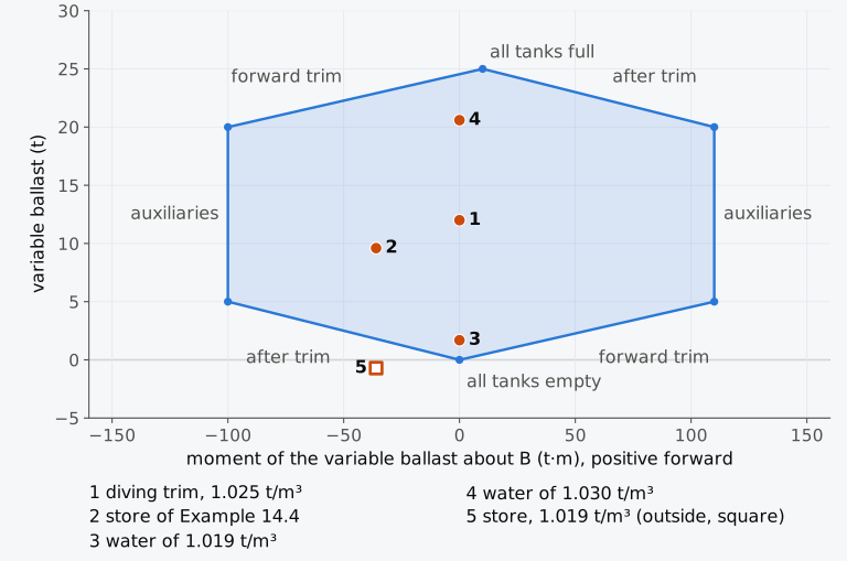
Figure 14.3 Equilibrium polygon of the submarine of Examples 14.3 and 14.4, with the variable ballast required in five conditions. Moments about B, positive forward; the side of each tank is labelled.
14.4.5 Diving and surfacing
While a submarine dives or surfaces, water stands at a free surface in its main ballast tanks. Its stability in this passage is estimated by filling the tanks in steps and adding, at each step, the weight, vertical moment and free surface moment of their water to those of the surfaced boat2. The least distance between the heights of M and of G, corrected for the free surfaces and plotted against the displacement, is the least metacentric height of the dive2. Each tank of a pair is taken with its own second moment, as if no water passed from side to side, although rolling makes the tanks on the low side fill faster2. In the example that Moore2 describes, M falls from its surfaced height as the displacement grows, until it meets B at the submerged displacement, where the waterplane vanishes. In real boats the free water in the main ballast tanks makes the transverse stability while diving or surfacing less than in either end state2. In the hull forms that Moore discusses, the levers at larger angles can stay positive even when the initial GM is small or close to zero2. This depends on the geometry of the hull, and the stability through the whole dive must be assessed rather than a small GM accepted on its own.
The method is applied in Fig. 14.4 to the boat of Example 14.3, an illustrative double-hull design. Its form follows the fleet submarines of the United States Navy in the Second World War, which were nearly circular in section, with very little freeboard and extreme tumblehome14. The outer hull is a circle 7.0 m in diameter up to a knuckle 5.0 m above the keel. Above the knuckle the sides lean inwards in straight lines until they meet the pressure hull, 5.8 m in diameter with its axis 3.9 m above the keel, whose crown forms the top of the hull at 6.8 m. Main ballast tanks 5.0 m long fill the whole section at each end of the buoyant hull, which is 60 m long, and the pressure hull lies between them. Along it, the space between the hulls holds fuel and trim tanks below 3.2 m and a port and a starboard main ballast tank above. The tapering bow and stern, the casing, a light structure above the hull that carries the deck, and the sail, the tower above the casing, are free-flooding.
With its main ballast tanks empty, the boat floats at a draught of 4.880 m, below the knuckle, and its reserve buoyancy is 28.4 % of the surfaced volume. Double-hull boats carry a larger reserve than the single-hull boats of the United States, whose reserve Khudyakov15 puts at about 12 to 15 %. On the surface the immersed section is a segment of the outer circle. The pressure on it acts through the centre of the circle, and M lies at that centre, 3.500 m above the keel. KG is taken as 3.000 m, which gives a surfaced GM of 0.500 m. The fleet submarines of the United States Navy were required to have a GM of at least 1.25 ft (0.38 m) in normal diving trim14. Submerged, B lies at the centroid of the envelope, 3.372 m above the keel and lower than the surfaced M.
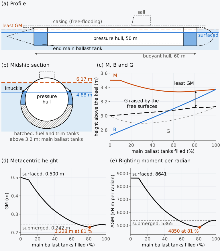
Figure 14.4 The double-hull submarine of Example 14.3 during a dive. (a) Profile and (b) midship section, to scale, with the water at the state of least GM; free-flooding parts dashed. (c) Heights of M, B and G, (d) GM and (e) the righting moment per radian ΔGM, against the filling of the main ballast tanks.
As can be seen from Fig. 14.4(c), M stays at the centre of the outer circle until the waterline reaches the knuckle, with the tanks 9 % full. Up to that point the water lies only in the end tanks, whose sections are the outer circle. As the boat heels, the circle turns beneath this water, whose free surface stays horizontal: the water keeps its place, with its centre of gravity on the vertical through the centre of the circle, and acts as a weight hung from that centre, which is also M. A weight at M adds to the displacement without a moment about M, so the righting moment per radian, , keeps its surfaced value, 8641 kN·m, and GM falls only because the displacement grows. Once the waterline climbs the inward-leaning sides, the waterplane narrows faster than it would on the circle, and M falls below the submerged B, to 3.336 m with the tanks 65 % full. Meanwhile the free surfaces of the end tanks, up to 7.0 m wide, raise G by as much as 0.15 m. The least GM, 0.228 m, occurs with the tanks 81 % full, when the water inside them reaches the height of the knuckle and the waterline outside lies 6.17 m above the keel. There the waterplane is only 3.60 m wide and BM is 0.111 m, while the end tanks are still 6.32 m wide and the free surfaces raise G by 0.100 m. Above the knuckle the end tanks narrow, and GM rises again to its submerged value, GB = 0.242 m.
The least GM of the dive lies below both the surfaced value, 0.500 m, and the submerged value, 0.242 m, as Moore2 states for real boats. As in his example, M falls below the height of the submerged B before it meets B. The righting moment per radian falls from 8641 kN·m surfaced to 4850 kN·m at the least GM, against 5365 kN·m submerged, with the unrounded GB of 0.2418 m. In its War Damage Report No. 58 of 1949, the Bureau of Ships of the United States Navy attributed the low GM of this passage to a waterplane of small second moment coinciding with the free surfaces of partly filled ballast tanks. It placed the least GM of double-hull boats with the tanks about 70 to 80 % full, in a condition lasting less than a second in a normal dive, and the specifications of those boats required a GM of at least 3 in (0.076 m) while submerging or surfacing14. The boat of Fig. 14.4 reaches its least GM with the tanks 81 % full, just above that range, when the water outside stands on the upper part of its outer hull. Khudyakov15 also places the least lateral stability of double-hull boats where this part of the outer hull enters the water. In this boat the fall of GM below its submerged value depends on the end tanks being undivided; divided at the centreline into a port and a starboard tank, they would keep GM above that value throughout the dive.
14.4.6 Stability on the surface
Surfaced, a submarine is a ship whose rounded hull is designed for the submerged state. Its metacentre lies higher on the surface than submerged, because of the waterplane16. In the boat of Example 14.3 the surfaced M lies 3.500 m above the keel and the submerged B 3.372 m. The part of the stability that comes from the form is small beside the part that comes from the low G, and metacentric heights about one tenth of those of naval surface ships are discussed for submarines on the surface16. Moore describes conventional surfaced submarines with positive levers well beyond 90° and emphasizes large rolling angles as a hazard even when capsize resistance is high2. These properties depend on the hull, loading and closure of its openings. Model tests in open water identified three causes of large roll: waves breaking in beam seas against the casing and against the sail; a sudden loss of stability when following seas wash over the casing; and large rolls in a trough after the boat emerges from a wave16. Avoiding the second would need a GM of the order of metres, which is not practicable, and too high a GM would make the boat stiff, with dangerous lateral accelerations16.
14.4.7 Passenger submersibles
Naval submarines follow the rules of their navies, which may be confidential; the German navy’s DMS 1030-2 is an example16. Passenger submersibles are covered by IMO’s Guidelines for the design, construction and operation of passenger submersible craft, MSC/Circ.981 of 29 January 2001. These recommend that such a craft keep an acceptable stability and trim while it ascends and descends, submerged and on the surface, and that it be able to remain on the surface with its hatches open without downflooding. It should have two independent means of surfacing upright, among them a means that works without electric power17. In an emergency it should be able to jettison enough mass to rise with its largest floodable volume, other than a space for people, flooded, and stay stable after any combination of dropped masses17.
The guidelines state aims and set no numerical limits. The United States Coast Guard gives a numerical method in its Navigation and Vessel Inspection Circular 5-93 (NVIC 5-93), which also writes the metacentric height of the submerged craft as GB. Submerged, the restoring moment is the weight times GB sin φ in roll and GB sin θ in trim, and the main hazard is the trimming moment of passengers moving inside the cabin18. For this hazard the circular asks for a least value
with = 0.1, a tenth of the passengers moving at once, each of mass = 72.5 kg, through the interior length of the main cabin. Here is the mass in kilograms of the loaded submersible without its free-flooding water ballast, and = 25° is the largest safe trim18. GB is measured by a submerged inclining test, in which an inclining mass moved a distance along the craft gives GB = from the trim θ that results18. On the surface, a test with 72.5 kg for each person on one side passes if no more than half the freeboard is immersed18.
14.5 Offshore units
The rig of the prologue belongs to a group of craft with rules of their own, the offshore units. The IS Code defines a mobile offshore drilling unit (MODU) as a ship able to drill for resources beneath the sea bed. A column-stabilized unit carries its main deck on columns or caissons that stand on underwater hulls or footings, and a surface unit operates afloat on a displacement hull of ship or barge form. A self-elevating unit can raise its hull clear of the sea on movable legs9. A unit is considered in its operating condition, on location for drilling, in its severe storm condition, with drilling stopped, and in its transit condition, moving between locations9.
14.5.1 Column-stabilized units at transit and operating draughts
The principle of the SWATH returns on a larger scale in the semi-submersible drilling unit, a column-stabilized unit whose underwater hulls are twin pontoons joined by braces or a ring pontoon. These hulls hold the ballast tanks and provide the buoyancy that the columns cannot. The deep draught and slender columns of the unit give it small motions, and the gap between the wave crests and its deck is a main consideration in its design6. The static stability of the unit comes from the surface-piercing columns, and it is analysed with curves of righting and heeling moments about every axis of inclination and in every mode of operation2.
At its transit draught the unit floats on its pontoons, whose large waterplanes, set far apart, make it very stiff. At its operating draught it has taken in ballast until the pontoons are deep under water, and its waterplane consists of the column sections only. For square columns of side standing on pontoons of height , the volume and the centre of buoyancy at a draught greater than are
where is the volume of the pontoons and the height of their centroid, and the second moment of the waterplane is that of the columns, by Eq. (14.2). The waterplane, and with it TPC and BM, change abruptly when the water passes the decks of the pontoons. The waterplanes of the casemate barge of Sec. 7.5.1 and of the floating dock of Sec. 13.4.1 change in this way as well.
Example 14.5. A semi-submersible at transit and operating draughts. A semi-submersible has two pontoons 100 m long, 16 m wide and 8 m high, with their centreplanes 60 m apart, and four columns 11 m square standing on them, centred 30 m to either side of the centreline. It floats in sea water. (a) Find its displacement, TPC, KB, and at its operating draught of 18.0 m with KG = 17.0 m. (b) It deballasts to its transit draught of 7.0 m by pumping out ballast water from tanks whose centroid lies 2.0 m above the base; find the ballast discharged, KG and in transit. (c) Find when the water is just above and just below the decks of the pontoons, 8.0 m, during the ballasting, taking the ballast as added at a fixed centroid 2.0 m above the base and leaving out the free surfaces of the tanks being filled.
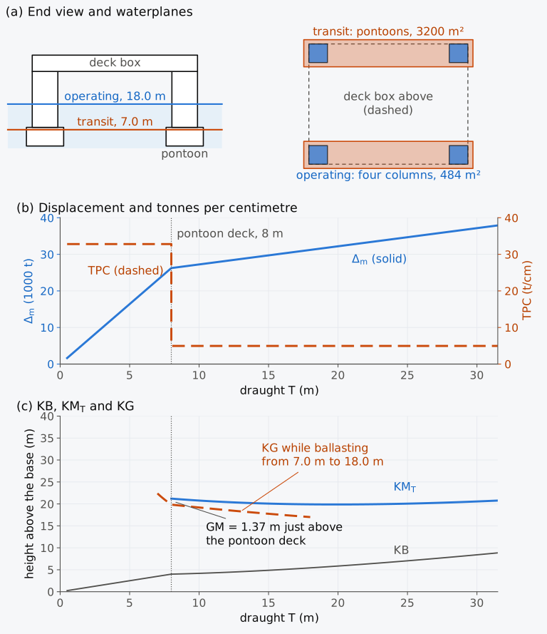
Figure 14.5 The semi-submersible of Example 14.5. (a) End view and waterplanes. (b) Displacement and TPC against draught. (c) KB, and the KG of the unit while it ballasts from transit to operating draught; below the pontoon deck is off the scale, 135.1 m at 7.0 m.
The curves of Fig. 14.5 break at the decks of the pontoons, and a hydrostatic table interpolated across 8.0 m would give a wrong draught for a given displacement, and a wrong GM, near the decks.
14.5.2 The axis of inclination
A conventional slender ship is usually least stable about its longitudinal axis, but the columns of a semi-submersible may give nearly equal second moments in the two directions. Its stability is therefore evaluated about several horizontal axes, at angles α to the centreline measured in the waterplane from the centreline (α = 0°) to the athwartships direction (α = 90°). The aim is to find the critical axis, the axis for which the criteria allow the lowest KG; it may change with the draught2. The 2009 Code for the Construction and Equipment of Mobile Offshore Drilling Units (2009 MODU Code), adopted by Resolution A.1023(26), accordingly asks that the curves of righting and heeling moments be related to the most critical axes19. Under the IS Code, units built on or after 1 January 2012 follow chapter 3 of this Code9.
For small angles, the second moment of the waterplane about an axis through its centroid at the angle α to the centreline follows from the principal second moments and by the rotation of axes,
and the least initial metacentric height lies about a principal axis, here the longitudinal axis, about which the unit heels. For the unit of Example 14.5 at its operating draught, with its columns centred 41.5 m forward and aft of the middle, = 4 × (1220 + 121 × 41.5²) = 838,449 m⁴ and = 15.98 m. About an axis at 45°, = 9.44 m, against = 2.90 m (Fig. 14.6(a)). At large angles the order can change, because the columns and the corners of the deck box enter the water at different angles about different axes. For a pontoon-based unit studied in this way, the axis parallel to the centreline gave the largest maximum lever but not always the highest initial GM2. The area under the curve was least for an axis near 42° to the centreline at a draught halfway up the columns, and near 49° at the pontoon draught2.
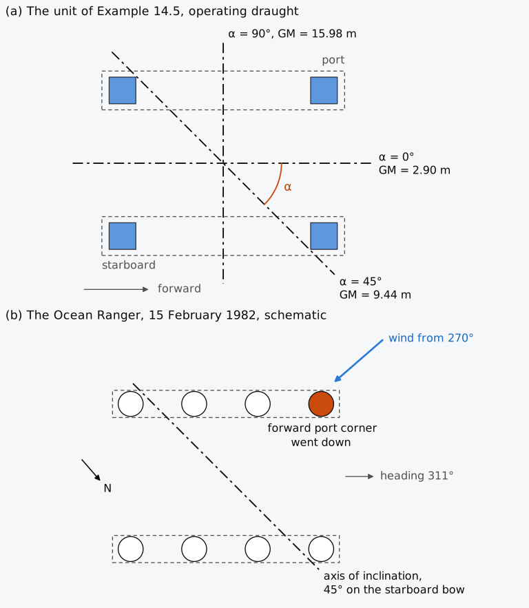
Figure 14.6 Axes of inclination in plan, bow to the right. (a) The semi-submersible of Example 14.5 at its operating draught, with GM about three axes. (b) The Ocean Ranger on 15 February 1982, schematic, not to scale.
14.5.3 The wind heeling moment
These righting moments are set against the heeling moment of the wind on every member above the water. The force on each member depends on its shape, its size and its height above the sea, since the wind strengthens with height. The 2009 MODU Code gives it for each exposed member as
in newtons, where and are the shape and height coefficients of the member, given in Table 14.1, = 1.222 kg/m³ is the density of the air, the wind speed in m/s and , in m², the projected area of the exposed surface, upright or heeled19. The height coefficient grows in steps with the height of the member above the sea. The wind is taken from any direction, at no less than 36 m/s (70 knots) in normal operation and 51.5 m/s (100 knots) in a severe storm19. A unit limited to sheltered waters may take 25.8 m/s (50 knots) as the least speed in normal operation19.
Table 14.1 Shape coefficients and height coefficients of the 2009 MODU Code19. The height coefficients continue to rise in steps above 76 m, to 1.80 at the top of the table.
(a) Shape coefficients
| Shape of the member | |
|---|---|
| Spherical | 0.40 |
| Cylindrical | 0.50 |
| Large flat surface (hull, deckhouse, smooth under-deck areas) | 1.00 |
| Drilling derrick | 1.25 |
| Wires | 1.20 |
| Exposed beams and girders under the deck | 1.30 |
| Small parts | 1.40 |
| Isolated shapes (crane, beam and so on) | 1.50 |
| Clustered deckhouses or similar structures | 1.10 |
(b) Height coefficients
| Height above the sea (m) | |
|---|---|
| 0 to 15.3 | 1.00 |
| 15.3 to 30.5 | 1.10 |
| 30.5 to 46.0 | 1.20 |
| 46.0 to 61.0 | 1.30 |
| 61.0 to 76.0 | 1.37 |
The projected areas include the surfaces that the heel exposes to the wind, such as the underside of the deck, with their own shape coefficients. Open truss work may be taken as 30 % of the block area of its front and of its back, or 60 % of the projected area of one side19. In this chapter no member is taken to shield another, and all four columns count in a beam wind. Table 3-2 of the Code gives by the height of the area above the sea, so a member that spans several bands is divided at their boundaries, each part taking the coefficient of its band; the commentary on the ABS rules for these units asks for sections of about 15.3 m in height and warns against one coefficient taken at the average height of a tall structure20. In this chapter every member is divided in this way at every heel, and the table of forces has one row per part; Example 14.6 states what one coefficient per member would give instead. The lever of the wind force is measured vertically from the centre of pressure of all the exposed surfaces to the centre of lateral resistance of the underwater body, with the unit free of its moorings19. The heeling moment is
where is the height of the centre of area of part and that of the centre of lateral resistance. The lever runs to the centre of lateral resistance, not to the waterline, because the wind drives the unit sideways and the water resisting that drift acts on the underwater body at that centre. The two forces form the heeling couple, as for the ship of Sec. 9.2.1. The moment is calculated at enough angles of heel to define its curve, and only for ship-shaped hulls may it be taken to vary as the cosine of the heel19.
14.5.4 The intact stability criteria
The intact criteria of the MODU Code are stated in terms of the areas under the moment curves, not of levers. The curves of righting and wind heeling moments first cross at the angle of steady heel, the first intercept, and may cross again at a larger angle, the second intercept, beyond which the heeling moment is the larger. For surface and self-elevating units, the area under the righting moment curve must exceed the area under the heeling moment curve by at least 40 %, both being taken to the second intercept or to the downflooding angle, whichever is less19. For column-stabilized units the two areas are taken to the downflooding angle, and the righting area must exceed the heeling area by 30 % or more19. Writing and for the two areas, which are the work done by the moments (Sec. 9.3.1), in kN·m·rad,
The righting moment must also be positive over the whole range from upright to the second intercept19. The unit must be able to reach its severe storm condition in a time consistent with the weather, by a procedure set out in its operating manual19. The Administration may accept alternative criteria of equal safety that take account of realistic wind and waves, the dynamic response of the unit, flooding in a seaway and its susceptibility to capsize19. The Code names Resolution A.650(16), for twin-pontoon semi-submersibles, as an example19, and in it the areas are measured beyond an angle of dynamic response to waves and fluctuating wind21.
Example 14.6. Wind heeling and the area ratio of the semi-submersible. The semi-submersible of Example 14.5 floats at its operating draught of 18.0 m, displacing 31,201 t, with KG = 17.0 m. The wind blows from port, at right angles to the centreline, and heels the unit starboard down. Upright, it acts on the four columns, each 11 m wide and exposed over the 14.0 m from the water to the deck box, on the side of the deck box, 94 m long and 7.0 m deep, from 14.0 m to 21.0 m above the water, and on the derrick, whose block is 12 m wide and 45 m high, from 21.0 m to 66.0 m above the water. The columns and the deck box are taken as large flat surfaces, and the derrick as open truss work. Under water, the pontoons present 2 × 100 × 8 m with their centre 14.0 m below the water, and the columns 4 × 11 × 10 m with their centre 5.0 m below it. (a) Find the upright wind heeling moment for a wind of 36 m/s and its lever, dividing each member at the band boundaries of the height coefficient. (b) The unprotected opening that sets the downflooding angle lies on the starboard side of the deck box, 35.5 m from the centreline and 33.5 m above the base, and reaches the water at 21.2°. Computed on the unit with the heeled areas at every 0.1°, the area under the righting moment curve to that angle is 88,944 kN·m·rad, and the area under the heeling moment curve is 29,957 kN·m·rad at 36 m/s and 61,306 kN·m·rad at 51.5 m/s. Judge the unit against the criterion of para. 3.3.1.2 of the 2009 MODU Code for column-stabilized units.
Table 14.2 The wind on the semi-submersible of Example 14.6, upright at its operating draught, 36 m/s. Each member is divided at the band boundaries of the height coefficient, one row per part, with the heights of its bottom and top above the water; the area is the length of the member (the derrick at 60 % of its 12 m) times the height of the part, with its centre at mid-height; lever to the centre of lateral resistance, 12.059 m below the water. The totals are summed before rounding.
| Member and part (m) | Area (m²) | Centre (m) | Force (kN) | Lever (m) | Moment (kN·m) | ||
|---|---|---|---|---|---|---|---|
| Columns, 4 × 11 m, 0 to 14.0 | 616 | 7.0 | 1.00 | 1.00 | 487.78 | 19.059 | 9297 |
| Deck box, 94 m, 14.0 to 15.3 | 122.2 | 14.65 | 1.00 | 1.00 | 96.76 | 26.709 | 2584 |
| Deck box, 94 m, 15.3 to 21.0 | 535.8 | 18.15 | 1.00 | 1.10 | 466.70 | 30.209 | 14,099 |
| Derrick, 60 % of 12 m, 21.0 to 30.5 | 68.4 | 25.75 | 1.25 | 1.10 | 74.47 | 37.809 | 2816 |
| Derrick, 30.5 to 46.0 | 111.6 | 38.25 | 1.25 | 1.20 | 132.56 | 50.309 | 6669 |
| Derrick, 46.0 to 61.0 | 108.0 | 53.5 | 1.25 | 1.30 | 138.97 | 65.559 | 9111 |
| Derrick, 61.0 to 66.0 | 36.0 | 63.5 | 1.25 | 1.37 | 48.82 | 75.559 | 3689 |
| Total | 1598 | 1446.07 | 48,264 |
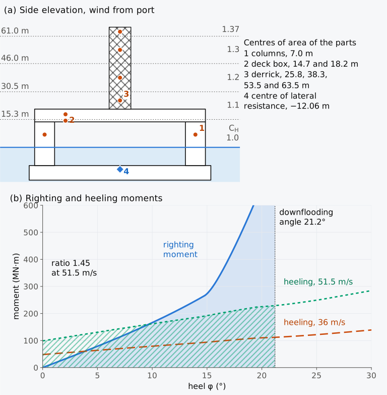
Figure 14.7 The wind on the semi-submersible of Example 14.6 at its operating draught, 18.0 m, with KG = 17.0 m. (a) Side elevation seen from starboard, with the bands of the height coefficient and the centre of area of each part of a member. (b) Righting and wind heeling moments; to the downflooding angle the righting area is shaded and the heeling area at 51.5 m/s hatched.
In Fig. 14.7(b) the righting moment grows almost linearly up to about 15° and then rises steeply. At 14.7° the deck of the high (port) pontoon reaches the surface and enters the waterplane, and at 19.6° the deck box on the low side begins to immerse, both before the downflooding angle. The heeling moment grows more slowly over the whole range, but at small heels it grows fast, since the underside of the deck box, 71 m wide, turns towards the wind: by 3.8° the box presents 11.7 m of height in place of 7.0 m, and the heeling moment at 36 m/s is 60.2 MN·m, 25 % above its upright value. The first intercept lies at 3.9° at 36 m/s, not at the 3.1° that the upright lever of 0.158 m and the GM of 2.90 m would give, and at 9.7° at 51.5 m/s. These are the angles at which the unit would heel under a steady wind of those speeds.
14.5.5 Calculator for the semi-submersible (Calculator 14.1)
With Calculator 14.1 you can set the draught and KG of the semi-submersible of Examples 14.5 and 14.6 and the speed of a wind from port. It gives the upright hydrostatics, the wind heeling moment of each member, the downflooding angle and the areas and with their ratio. The ratio is compared with 1.3 for column-stabilized units, and the calculator flags negative righting levers within the integrated range. It does not carry the Code’s check to the second intercept or search for the critical axis, so its results are not a complete MODU assessment. The unit heels about its longitudinal axis only, and its members are clipped at the water at constant displacement every 0.1°. Its draught may lie between 3 m and 30 m. Near the decks of the pontoons the calculator states the range of heel over which the upright GM holds.
14.5.6 Damage and watertight integrity
A column-stabilized unit must also survive damage. The 2009 MODU Code assumes damage only to the columns, underwater hulls and braces on the periphery of the unit, on their exposed sides. The damage extends 3 m vertically and penetrates 1.5 m, anywhere between 5 m above and 3 m below the draughts of the operating manual19. After such damage, in a wind of 25.8 m/s (50 knots) from any direction, the unit must not incline by more than 17°, and openings below the final waterline must be watertight and those within 4 m above it weathertight19. From the first intercept to the lesser of the second intercept and the extent of weathertight integrity, the righting moment curve must have a range of at least 7°. Within that range the righting moment must, at some angle, reach at least twice the wind heeling moment19. Without wind, the flooding of a pump room, a room with machinery cooled by sea water, or a compartment next to the sea must leave an inclination of no more than 25° and at least 7° of further range of positive stability19. The openings of chain lockers and of other buoyant spaces that can flood count as downflooding points19.
14.5.7 Self-elevating units, spars and floating wind turbines
Of the other offshore units, a self-elevating unit, or jack-up, is afloat when it is towed between locations, and the criterion of surface and self-elevating units, with its ratio of 1.4, then applies to it. Its legs, raised high above the hull, add a large windage where the height coefficient is largest. Heel and trim interact strongly in such units. A curve of levers computed about a fixed axis may fail to converge because the unit is overturning about another direction, and the idea of a single critical axis becomes questionable2.
A spar is a single large vertical cylinder weighted at its bottom, which places its centre of gravity below its centre of buoyancy6. For a cylinder of diameter floating at the draught , and , and BM = , a few decimetres for a deep spar. Like a submarine, the spar owes its stability to G lying below B. A tension leg platform, by contrast, has more buoyancy than weight and is held down by vertical tendons that restrain its heave, roll and pitch6. Its stability as a free-floating body matters during tow-out and installation.
Floating offshore wind turbines stand on floaters of these forms: spars, semi-submersibles and barges, which are stabilized by their hydrostatics, and tension leg platforms22, which rely on their tendons6. Their stability is not covered by the IMO instruments of this chapter, and it is judged in load cases tied to the operation of the turbine, producing power or parked in extreme seas22.
14.5.8 The Ocean Ranger
With the critical axis and the downflooding points in view, we can now return to the Ocean Ranger. The rig had been designed to the 1973 Rules for Building and Classing Offshore Drilling Units of the American Bureau of Shipping. Under them it was to withstand the overturning moment of a steady wind of 70 knots from any direction, and of 100 knots after a change of loading1. The design was also to survive the flooding of any watertight compartment extending to within 5 ft (1.5 m) of the draught1. The operating manual required a GM of at least 1.5 ft (0.46 m) in every direction1. On 15 February the transverse GM was about 6 ft (1.8 m), and the longitudinal GM, about 4 ft (1.2 m), was smaller1. Unlike a ship, the rig was less stable in trim than in heel.
The ballast valves of the rig were worked by solenoids that admitted compressed air to the valve gear, and all closed under springs if the control air failed1. Without electrical power the solenoids could be worked by hand with brass rods threaded into them, but the Board found no evidence that anyone aboard had ever used the rods, or that instructions for them were on board1. The wind had veered from 220° at 1730 to 270° at 2330, and the rig was moored on a heading of 311°, so the wind came from about 40° on the port bow1. The list by the bow and to port lowered the corner that faced the wind and the waves. The Merchant Marine Technical Branch of the United States Coast Guard later made its own calculations, for calm water, with G 63 ft (19.2 m) above the keel and the loading of the stability report of 9 February1. On this heading, the Branch found, the rig would have inclined about a horizontal axis 45° on its starboard bow1, neither fore and aft nor athwartships (Fig. 14.6(b)). An inclination about such an axis that puts the bow down also puts the port side down, which agrees with the messages.
Each corner column held a chain locker, which could flood through three chain pipe openings of 6 ft² (0.56 m²) and three wire rope trunk openings. Only the chain pipe openings were shown on the damage control plan, and the operating manual gave no guidance on keeping water out of the lockers1. The openings, far above the sea while the rig floated upright, came towards the waves as its forward corner went down, and the flooding of the forward chain lockers caused the capsize1.
14.6 High-speed and dynamically supported craft
14.6.1 Modes of support and the requirements of the HSC Code
The units of Sec. 14.5 are judged at rest in a steady wind. A high-speed craft must keep its stability in motion, when lift may carry part of its weight. In the displacement mode of Sec. 14.1.2 a planing craft, a hydrofoil or an air-cushion vehicle floats on its hull, and its stability follows the methods of the earlier chapters. These craft also have weaknesses of their own, among them a low freeboard, which lets them ship and trap water, and large shifts of G when foils are extended or retracted. They have few watertight bulkheads and thin shells that waves or debris can damage at speed, and catamarans of small waterplane risk large unsymmetrical flooding2.
At speed the forces that carry such a craft are no longer hydrostatic, and the 2000 HSC Code asks that tests or calculations also address the hazards to which high-speed craft are known to be liable according to their type3. Among them are directional instability, a tendency to leave the course, often coupled with roll and pitch, and a dynamic loss of longitudinal stability in planing craft. Broaching, a sudden turn broadside to following seas, and bow diving, the burying of the bow, occur at speeds near the speed of the waves. The hazards of particular types include a loss of transverse stability with speed in monohulls, porpoising and chine tripping of planing monohulls, and the plough-in of air-cushion vehicles, in which the bow digs into the water. Others are pitch instability of SWATH craft and, in surface effect ships, a loss of effective GM in fast turns and resonant rolling in beam seas3. These are matters of the motions of the craft rather than of its hydrostatics2.
The Code also limits the heel of passenger craft, for which the passengers are taken at 4 persons per square metre, 75 kg each, crowded to one side on the decks of the assembly stations. Their centre of gravity lies 0.3 m above the seat when seated and 1.0 m above the deck when standing3. In the displacement mode the heel in still water must not exceed 10° in any permitted loading with uncontrolled movements of the passengers3. In the non-displacement mode the limits are 10° for the heel from passenger movements or from the beam wind of Annex 6, 8° for the outward heel in a turn, and 12° for the heel from the wind and the turn together3. Annex 6 of the Code, on the stability of hydrofoil craft, adds that the heel caused by passengers concentrated on one side should not exceed 8° in the foilborne mode and 12° in the transitional mode. The Administration sets that concentration of passengers, with the guidance of Annex 7 of the Code3.
14.6.2 Planing craft
A planing hull at speed is carried largely by the dynamic pressure on its bottom. The transverse stability of planing boats with hard chines, the sharp corners between bottom and sides, is described by Moore in terms of the broad hulls and high transverse stiffness of many established designs2. Planing hulls tend to be much stiffer in roll at high speed than at rest, particularly hulls of low deadrise, and their stability falls as the deadrise grows. Deep-V hulls of high deadrise have needed longitudinal strakes or spray strips to obtain a satisfactory transverse stability2. The 2000 HSC Code, however, lists a reduction of transverse stability with increasing speed among the hazards of monohulls. A gain of stiffness at speed cannot be assumed for every form of hull, and whether it occurs is established by tests or trials.
Porpoising, among the hazards of Sec. 14.6.1, is a periodic heaving and pitching of a high-speed craft, met mainly in calm water and sustained by energy taken from the thrust6. In planing monohulls it results from a loss of longitudinal stability2 and can become violent3. Chine tripping, another hazard of these hulls, occurs when the immersion of a chine produces a strong capsizing moment3.
14.6.3 Hydrofoil craft
A hydrofoil craft is carried clear of the water by the lift of its foils in the non-displacement mode3, and its stability while foilborne is wholly hydrodynamic2. Surface-piercing foils give stability without automatic control, because a heel immerses more foil on the low side and less on the high side, and the difference of lift rights the craft2. Fully submerged foils keep their immersed area as the craft heels. A craft that runs on them depends almost entirely on automatic control of the foil angles, or of flaps on their trailing edges, for its transverse stability and for its height and trim2.
To find the metacentre of a surface-piercing foil, let the foil be a V, symmetric about the centreline of the craft, with each of its two panels inclined at the dihedral angle β to the horizontal. The panels pierce the surface at two points a distance apart, the waterline span, and the apex lies at the depth . Let each panel develop a lift per unit of immersed length, normal to the panel. Upright, each panel is immersed over , and the vertical components of the two normal forces add up to , which equals the weight that the foil carries. Heeled by the angle φ, starboard down, with its height held, the immersed lengths of the starboard and port panels, measured from the apex, become
and the low panel gains immersed length while the high panel loses it. The resultant of the normal forces and turns from the axis of the craft by exactly φ towards the high side, and stays vertical. Each force acts at the middle of its immersed length, with the moment about the apex, and together they place the line of the resultant across the centreline at the height above the apex. As φ tends to zero this point tends to above the apex, that is, to
above the water. This point is the metacentre of the foil: the lift of the heeled foil acts vertically through it, as the buoyancy of a heeled ship acts through M. Its height depends only on the span and the dihedral, and the span is set by the running height. At a higher speed, or with less weight, the foil carries its share of the weight on a shorter immersed length, and the craft rises, the span shrinks and M falls. The foilborne GM thus changes with speed and load. The model leaves out the loss of lift near the surface and at the tips.
Let a craft share its weight between a bow foil, which carries the fraction , and a stern foil, which carries , with G at the height above the water. For a small heel its righting moment is , where and are the heights of the metacentres of the two foils. With , and , the waterline spans and dihedrals of the bow and stern foils, its metacentric height is
Annex 6 of the 2000 HSC Code gives the expression of Eq. (14.16), in terms of the shares of the load carried by the bow and stern foils, their widths and inclinations and the height of G above the water, as one possible method of estimating the foilborne metacentric height of a given arrangement of foils at the design stage3,23. The older 1994 HSC Code gave this expression as well2,24. The 2000 Code also asks that the stability found in the transitional and foilborne modes by calculation or from model tests be verified by full-scale tests3. In these tests known heeling moments are applied with ballast placed off the centreline, and the resulting heels are measured3,23. In practice the foilborne longitudinal metacentric height lies between 3.5 and 5.5 times the distance between the foils2. With fully submerged foils the controls give so large a righting moment at normal speeds that wind and off-centre passengers have little effect2. The moment of the ailerons, flaps acting in opposite senses on the two sides, must exceed the roll disturbance from the orbital velocities of beam seas throughout the operating envelope2.
Example 14.7. The metacentric height of a hydrofoil craft. A passenger hydrofoil of 130 t runs foilborne on two surface-piercing V-foils. The bow foil carries 55 % of the weight, pierces the water over a span of 7.2 m and has its panels inclined at 28° to the horizontal; the stern foil carries 45 % of the weight, pierces the water over a span of 5.0 m and has its panels inclined at 32°. When the craft is foilborne, G lies 2.2 m above the water. (a) Find the depth of the apex of each foil and the height of its metacentre above the water. (b) Find the foilborne GM. (c) Find the heel when 40 passengers of 75 kg each move 4.0 m towards the starboard side.
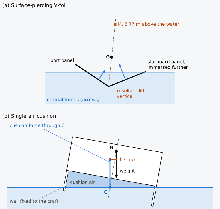
Figure 14.8 Craft supported by lift and by air, seen from aft; the centreline of each craft dashed. (a) The bow foil of Example 14.7, heeled 6° with its height held. (b) A craft on a single air cushion enclosed by walls fixed to it, heeled 10°, with G 3.2 m above C. Arrow lengths are not to scale.
14.6.4 Air-cushion vehicles, surface effect ships and wing-in-ground craft
An air-cushion vehicle is carried, wholly or in a significant part, by a cushion of air that is generated continuously and depends on the nearness of the surface beneath it3. Consider a single cushion, enclosed by walls or skirts fixed to the craft and reaching down to the water, with a uniform pressure in its air. The underside of the craft, its walls and the water surface inside them enclose the air. A uniform pressure exerts no resultant force or moment on a closed surface, and the force of the air on the craft therefore equals and opposes its force on the water surface. That force is vertical, equal to the weight, and acts through the centroid of the cushion area on the water, the point C where the centreline of a symmetric craft meets the water surface inside the cushion. The pressure on the underside by itself acts along the centreline of the craft, through G, and gives no couple. The couple comes from the walls, the high wall being exposed to the air over a greater depth than the low wall. With G a height above C, measured along the centreline, a heel φ moves G a distance to the low side of the vertical through C (Fig. 14.8(b)), and the righting lever and the metacentric height are
and such a craft is unstable in heel, and in trim as well2, like a submerged body whose centre of buoyancy lay below G.
Dividing the cushion by skirts or air jets, at least once fore and aft and once athwartships, improves its stability at low speeds. With little leakage the air on the low side is compressed and its pressure rises, while the air on the high side expands2. In a real craft air leaks continuously under the seals. When the craft heels, the leakage on the low side shrinks and the pressure there rises, and flexible skirts add a further righting moment as they deflect2. Air-cushion vehicles have occasionally ploughed in or capsized, usually while turning in severe weather, and their dynamic stability is examined by experiments and full-scale trials2.
A surface effect ship is an air-cushion vehicle whose cushion is held wholly or partly by permanently immersed hard structures3. Its rigid sidewalls give it buoyancy and transverse stability, calculated as for a catamaran except that the water inside the cushion stands lower than outside. Flexible seals at the bow and stern add to its longitudinal stability, and a long, narrow surface effect ship needs particular care2.
A wing-in-ground craft flies above the water on the lift of its wings close to the surface, at speeds that can exceed 100 knots (51 m/s). The main concern is its longitudinal stability, which can be lost when the craft passes from flight in ground effect to free flight2. IMO’s Guidelines for wing-in-ground craft, MSC.1/Circ.1592 of 18 May 2018, which revoked the earlier interim guidelines, ask that the longitudinal stability of the craft in flight be calculated and its dynamic stability verified25.
Table 14.3 compares the main craft of this chapter, which differ in the source of their righting moment and in the way they lose stability.
Table 14.3 The main craft of this chapter compared by the source of their righting moment, the way their stability is lost and the analysis or criterion applied to them. Multihulls include catamarans and trimarans.
| Craft | Treatment |
|---|---|
| Source of the righting moment | |
| Multihulls | Hulls set apart, each adding its area times the square of its distance from the centreline, Eq. (14.2) |
| SWATH | Struts of small area set far apart, over deep lower hulls (Sec. 14.3) |
| Submarine | Submerged, G below B, with (Sec. 14.4.2); on the surface, the waterplane and a low G (Sec. 14.4.6) |
| Semi-submersible | The columns at the operating draught, the pontoons in transit (Sec. 14.5.1) |
| Hydrofoil | The difference of lift on surface-piercing foils, through the metacentre of Eq. (14.15); automatic control on submerged foils (Sec. 14.6.3) |
| Air-cushion craft | Destabilizing for the fixed-wall, uniform-pressure single cushion with G above C, Eq. (14.17); a divided cushion, leakage and skirts (Sec. 14.6.4) |
| How stability is lost | |
| Multihulls | The lever peaks soon after a hull lifts or a deck edge immerses, and vanishes at a moderate angle (Sec. 14.2.3) |
| SWATH | A small GM, from deep buoyancy and a high deck (Sec. 14.3); pitch instability at speed (Sec. 14.6.1) |
| Submarine | The least GM of a dive, with wide free surfaces as the waterplane narrows (Sec. 14.4.5) |
| Semi-submersible | GM falls abruptly as the water passes the decks of the pontoons (Example 14.5); inclination about a critical axis, and downflooding (Sec. 14.5.8) |
| Surface-piercing hydrofoil | GM falls at a higher speed or a lower load, as the span shrinks (Sec. 14.6.3) |
| Air-cushion craft | Plough-in or capsize, usually while turning in severe weather (Sec. 14.6.4) |
| Analysis or criterion | |
| Multihulls | The curve at constant displacement; Annex 7 of the 2000 HSC Code (Sec. 14.2.6) |
| SWATH | Computed as for a ship and judged by the criteria for catamarans (Sec. 14.3) |
| Submarine | The angles and the trim tanks of Eqs. (14.6) and (14.7); for passenger submersibles, the least GB of Eq. (14.9) |
| Semi-submersible | GM about every axis, Eq. (14.11); the area ratio of the 2009 MODU Code, Eq. (14.14) |
| Hydrofoil | The GM of Eq. (14.16), from Annex 6 of the 2000 HSC Code, with full-scale heeling tests (Sec. 14.6.3) |
| Air-cushion craft | Experiments and full-scale trials (Sec. 14.6.4) |
14.7 Unconventional craft in industry today
This section describes practice in 2026. The sources on the DNV standard for floating wind turbines, the amendments to the 2000 HSC Code and the Titan investigation of the Transportation Safety Board of Canada were read on 2 November 2026, and the others in October 2026.
Offshore units. The Marine Safety Center of the United States Coast Guard reviews the stability calculations of mobile offshore drilling units following its Plan Review Guide C2-33. Its minimum items include a curve or table of maximum KG, the downflooding points and the damage stability calculations26. The Center builds its own model of the hull, preferably in the programs GHS or HECSALV26. The curves of maximum KG combine the intact and the damage results, and moments from wind-tunnel tests are accepted only where they are as conservative as the moments that 46 CFR 174.055 gives by calculation26. DNV’s HydroD, for example, is described by its maker as computing the intact and damaged stability of semi-submersibles, tension leg platforms, spar buoys and ships, with wind heeling moments and an analysis of maximum KG27.
Floating wind turbines. IEC 61400-3-2:2025 of the International Electrotechnical Commission, published on 22 January 2025, covers the design of floating offshore wind turbines. It replaced the technical specification IEC TS 61400-3-2 of 2019 and updated its guidance on damage and dynamic stability28. DNV lists its standard DNV-ST-0119, Floating wind turbines, in an edition of October 2026 on its web page29. In its revision presented in 2021, the stationary load cases were checked by the comparison of areas used in all the standards, with a safety factor of 1.3 for semi-submersibles22, the factor of the 2009 MODU Code for column-stabilized units. The heel about the critical axis, which may combine roll and pitch, was also to be studied in simulations in the time domain22. The text of the current edition is not publicly available, and its provisions are not described here.
High-speed craft. The January 2026 amendments to the 2000 HSC Code concern fire-extinguishing media and the safety-certificate equipment record; they do not change the stability criteria used here30. In model experiments on the criteria of the 2000 HSC Code, commissioned by the United Kingdom’s Maritime and Coastguard Agency, six models (monohulls, catamarans and a trimaran) were tested in 53 configurations in regular waves31. The study concluded that the criteria do not give immunity from capsize in typical operational sea states, and that the vulnerability of a craft to capsize depended mainly on its range of residual stability. The multihulls tended to be safer because their margins over the criteria were larger, which the study attributed to their typical proportions, not to the Code31.
Passenger submersibles. The submersible Titan imploded during a dive to the wreck of the Titanic in June 2023, and five people died. The Marine Board of Investigation of the United States Coast Guard found the primary contributing factors in the operator’s inadequate design, certification, maintenance and inspection process. It recommended that federal and international requirements be extended to all submersibles making scientific or commercial dives32. In Canada, Ship Safety Bulletin 03/2026 of Transport Canada, issued on 8 April 2026, explains Transport Canada’s policy that non-pleasure passenger submersibles registered in Canada are to be constructed according to MSC/Circ.981. A foreign submersible operating in Canadian waters may be inspected and must show compliance with those guidelines or with equivalent requirements of its flag state33. In releasing its report in June 2026, the Transportation Safety Board of Canada found that the Titan had operated from Canada without regulatory oversight. It also noted that the guidelines of IMO for the design and operation of submersibles are not binding on member states, which leaves oversight inconsistent around the world34.
14.8 From statics to motions
The fourteen chapters of Hydrostatics & Stability treat the hydrostatic basis of stability, the equilibrium of a floating body in still water. Where the subject calls for it they also give an introductory treatment of dynamic effects, as in the energy of heeling, the weather criterion and the righting lever in waves of Chapter 9, and in the craft of this chapter that are carried at speed by lift or by air. The chapters cover the hydrostatics of a hull from its offsets, its floating position and its curve of righting levers at any heel and trim, and the effects on them of loading, free surfaces, damage and support by blocks or the ground. Throughout, the stability is judged against the criteria of IMO and of national Administrations. These methods apply equally to craft carried by separated hulls, by columns or by their own submerged volume, provided that the changes of the waterplane with draught and heel are followed. Chapter 1 opened with the losses of Vasa and HMS Captain, and with Captain set beside Monarch, a ship of much higher side. The static questions that these ships raised, like those raised by the Ocean Ranger, can now be framed and tested with these methods; reconstructing an accident also needs reliable loading, damage and environmental evidence.
Most of the hazards listed in Sec. 14.6.1 arise from the motions of a craft at speed or in waves. So do the dynamic response to waves and gusts that Resolution A.650(16) takes into account for twin-pontoon semi-submersibles, and the failure modes in waves that the second generation intact stability criteria assess (Sec. 11.8). Their analysis belongs to seakeeping, to manoeuvring, and to the resistance and propulsion that set the speed of a craft, which are the subjects of the OpenNAOE books in preparation. Each of those subjects begins with a ship that floats at a known waterline with a known centre of gravity, and that is where these chapters leave it.
Summary
- The craft of this chapter divide, shrink or remove the waterplane that gives a ship its form stability, or rise out of the water at speed. A high-speed craft, as the 2000 HSC Code defines it, can reach = 3.7 m/s or more, with in m³ at the design waterline. That threshold corresponds to a volumetric Froude number of 1.18.
- For small heels each hull of a multihull adds to the second moment of the waterplane its own second moment and its area times the square of its distance from the centreline, Eq. (14.2). For the box demihulls of Example 14.1, 3.0 m wide at a draught of 1.5 m with KG = 4.0 m, a spread of 9.0 m multiplies the BM of a demihull by 28 and gives GM = 10.75 m.
- The curve of righting levers of a catamaran of wall-sided demihulls follows the wall-sided formula until a hull lifts or a deck edge immerses, whichever comes first. It peaks soon after and vanishes at a moderate angle, 64.7° in Example 14.1, computed at constant displacement with the trim held. With a cross structure that gives no buoyancy, the craft is stable upside down. For multihull high-speed craft, Annex 7 of the 2000 HSC Code asks for an area that grows as the angle of the largest lever falls.
- A small waterplane lowers TPC directly, and a SWATH sinks further for each tonne added. The GM of a SWATH, KB + − KG, depends also on the spread of its hulls and on its loading, and its deep buoyancy and high deck can leave it smaller than that of a conventional ship. The design tends to small motions in waves while the natural periods of heave, pitch and roll lie well above the periods of the waves met.
- A submerged submarine has its metacentre at B and the metacentric height GB for every horizontal axis, apart from the movement of liquids and loose items; there is no hydrostatic yaw stiffness. For a rigid hull in uniform water the depth equilibrium is neutral, whereas most submarines are unstable in depth because the hull compresses more than the water. In Example 14.3 a moved weight trims it 216 times as far as on the surface, and trim tanks compensate every change of load by the rule of the lever. The equilibrium polygon of the variable ballast tanks shows which loading conditions they can meet. The boat of Examples 14.3 and 14.4 and Figs. 14.3 and 14.4 is an illustrative design, not a real boat. In its dive the waterplane narrows while the main ballast tanks still have wide free surfaces, and the least GM, 0.228 m with the tanks 81 % full, lies below both the surfaced 0.500 m and the submerged 0.242 m. With its end tanks divided at the centreline, GM would not fall below the submerged value.
- As a semi-submersible ballasts past the decks of its pontoons, its waterplane changes from the pontoons to the columns. In Example 14.5, with the ballast at a fixed height and no free surfaces, falls from about 99 m to 1.37 m; the larger value holds only until a pontoon deck edge reaches the water. Examples 14.5 and 14.6 consider heel about the longitudinal axis only; the stability of a unit is checked about its critical axis, which may lie at an angle to the centreline.
- Under the 2009 MODU Code the wind on each member is computed with shape and height coefficients, the height coefficient rising in bands at which a tall member is divided. For column-stabilized units the area under the righting moment curve must exceed that under the heeling moment curve by 30 %, both taken to the downflooding angle, and the righting moment must be positive up to the second intercept. The unit of Example 14.6, at its operating draught with KG = 17.0 m, has ratios of 2.97 at 36 m/s and 1.45 at 51.5 m/s in a beam wind, with no member taken to shield another. The Ocean Ranger was lost after its ballast control failed and water entered the chain lockers of its forward columns.
- High-speed craft are examined against a list of dynamic hazards, and passenger craft must keep within stated heels. A static calculation, such as that of Example 14.7, is not a complete assessment of the safety of such a craft in operation. A symmetric V-foil held at its height has its metacentre above the water for a given span, which changes with speed and load. The result is for small heels and leaves out the loss of lift near the surface and at the tips. A single air cushion of uniform pressure, enclosed by walls fixed to the craft, gives GM = −, with measured from the water surface inside the cushion.
Notes on the data
The Ocean Ranger. The account follows the report of the National Transportation Safety Board, NTSB-MAR-83-2, read in the copy held by the United States Coast Guard. None of the data of the Ocean Ranger is used in the calculations. Figure 14.6(b) is a schematic: it shows the eight columns on two lower hulls, the heading, the wind at 2330 and the axis of inclination that the report gives, but not the breadth of the rig or the shapes and sizes of its columns.
The craft of Fig. 14.1. Each craft displaces 2000 m³. The monohull is of Wigley form, 60 m × 12 m × 6.25 m, and the catamaran has two such hulls 6 m wide at a spread of 16 m; for a Wigley hull of length and breadth , and . The SWATH has two circular lower hulls 4 m in diameter and 56 m long under struts 44 m × 2 m at a spread of 16 m, immersed 3.37 m above the lower hulls. The semi-submersible has two pontoons 40 m × 7 m × 3 m, centred 10 m from the centreline, under four columns 5 m square, centred 15 m forward and aft of the middle and immersed 3.2 m above the pontoons. The submarine is a cylinder 6 m in diameter and 70.7 m long.
The catamarans. Their curves of righting levers are computed by the engine of Chapter 8 on hulls whose sections are closed polygons, a polygon for each demihull, with the cross structure left out and the trim held at zero. The Wigley demihulls have the sections of Chapter 1 below the design waterline and vertical sides above it, up to the deck at 10 m, integrated by Simpson’s rule over 201 stations. Levers are computed every 0.5° for the twin-box catamaran, every 1° for the Wigley catamaran and every 5° for the tests of Explorer 14.1. The largest levers, the angles at which the levers vanish and the heels at which a hull lifts or a deck edge reaches the water are refined between these points.
The submarine. The boat of Examples 14.3 and 14.4 and Fig. 14.4 is an illustrative design, not a real boat, with a constant section along its 60 m buoyant hull. The outer circle has a half-breadth of 3.162 m at the knuckle, and the straight sides are tangent to the pressure hull 6.094 m above the keel and 1.896 m from the centreline. The envelope has a section of 36.779 m² and a volume of 2206.75 m³. Each end main ballast tank holds 183.90 m³, and each side tank 60.09 m³. The ends of the pressure hull are taken as flat bulkheads, and the fuel and trim tanks between the hulls below 3.2 m as part of the weight of the surfaced boat, without free surfaces. The free-flooding bow and stern (6 m and 10 m long in the drawing), casing (2.0 m wide, to a deck 7.6 m above the keel) and sail (7.0 m long, to 11 m above the keel) do not enter the calculation. The trunk and masts inside the sail are left out, as are the residual water and flood openings of the main ballast tanks and the longitudinal free surfaces. The surfaced KG, 3.000 m, is chosen to give a GM of 0.500 m. In the dive the water is raised in steps of 0.02 m to one level in all four main ballast tanks and added as weight together with the free surface of each tank, the trim is held at zero, and each step is floated upright by the engine of Chapter 8. At the states of least KM and least GM, GM is also found from the boat heeled 0.05° with the water of each tank levelled at that heel, and the two agree to within 0.0001 m. For Fig. 14.3 the forward and after trim tanks are taken to hold 5.0 t each and the auxiliary tanks 15.0 t at B, and the boat in diving trim in water of 1.025 t/m³ to need 12.0 t of variable ballast with no moment about B. The envelope and the main ballast tanks are symmetric fore and aft, and a change of density gives no moment about B. In Sec. 14.4.5 and Fig. 14.4 the submerged values use the unrounded KB = 3.3715 m and KG = 3.1298 m, so that GB = 0.2418 m.
The semi-submersible. The upright hydrostatics of the unit of Examples 14.5 and 14.6 are computed in closed form. The heeled unit is computed by the engine of Chapter 8 on the pontoons, the columns and the deck box, all taken as watertight, with stations in pairs at every break, at constant displacement every 0.1° and with the trim held at zero. The unprotected opening that sets the downflooding angle lies on the side of the deck box, 35.5 m from the centreline and 33.5 m above the base, 1.5 m above the bottom of the box. For the wind, each member is a prism along the unit, whose projected area is its length times the vertical extent of its section at the heel. At every heel that extent is divided at the band boundaries of the height coefficient (15.3, 30.5, 46.0 and 61.0 m above the water), each part taking the coefficient of its band with the centre of its area at its mid-height; with one coefficient per member, from the height of its centre of area, the upright moment at 36 m/s would be 47,619 kN·m in place of 48,264 kN·m, and the heeling areas to the downflooding angle would differ by less than 0.1 %: the deck box, whose projection grows fast with the heel, would then take 1.1 over the whole of it, part of which lies below 15.3 m, while the derrick would take 1.2 over its whole height. The derrick is a block 12 m × 12 m × 45 m on the deck, taken at 60 % of its projected area. The centre of lateral resistance is the centre of the projected area under water at each heel, and the ballast is taken at a fixed centroid 2.0 m above the base, without free surfaces.
The foil and the cushion. Figure 14.8(a) is drawn at 6° to make the heel visible; at that angle the line of the resultant crosses the centreline 0.35 m above M and passes 0.04 m from M horizontally. The faster running condition of Example 14.7 keeps the dihedrals and the shares of the weight, and takes the lift per unit of immersed length as proportional to the square of the speed. The craft of Fig. 14.8(b) is 8.0 m wide and 3.0 m high, with its underside 0.8 m above the water surface inside the cushion and G 2.4 m above the underside, 3.2 m above C; its walls reach 1.0 m below that surface when the craft is upright.
The animation. Animation 14.1 uses the floating positions of the twin-box catamaran of Example 14.1, computed on the hull at constant displacement every 0.6° from 0° to 72°.
Exercises
Under each exercise, “Show answers” opens its short answers and “Show full solution” its worked solution. Sea water has a density of 1.025 t/m³ and = 9.81 m/s². Heel φ is positive with the starboard side down, and the trim angle θ is positive bow up.
14.1 Three craft have the following volumes of displacement at their design waterlines and maximum speeds: (a) a monohull of 350 m³ that can reach 28 knots; (b) a catamaran of 1100 m³ that can reach 30 knots; (c) a monohull ferry of 5000 m³ that can reach 22 knots. For each, find the speed at and above which a craft of that volume counts as a high-speed craft, in m/s and in knots, and decide whether the craft is a high-speed craft. Take 1 knot = 0.5144 m/s.
14.2 A trimaran has a box-shaped main hull 50 m long and 5.0 m wide, floating at a draught of 2.4 m, and two box-shaped floats, each 18 m long and 1.4 m wide, whose bottoms lie 1.8 m above the keel of the main hull and whose centreplanes lie 9.0 m from the centreline. The cross structure gives no buoyancy, and KG = 3.2 m. Find (a) the volume of displacement and KB; (b) the second moment of the waterplane about the centreline, and the share of it that comes from the floats; (c) BM and GM, and the BM of the main hull floating by itself at 2.4 m.
14.3 A catamaran has two box demihulls 24 m long, 2.0 m wide and 4.0 m deep, with their centreplanes 7.0 m apart, and floats at a draught of 1.0 m with KG = 3.2 m. The cross structure gives no buoyancy. (a) Find its displacement, BM and GM. (b) Find the angle at which the high hull begins to lift, show by Eq. (14.5) that it comes before the immersion of the deck edge of the low hull, and find the righting lever at that angle. (c) Find GM when the craft floats upside down. (d) With Explorer 14.1, find the largest righting lever, the angle at which it occurs, the angle at which the lever vanishes and the heel at which the deck edge of the low hull reaches the water. (e) Find the area under the curve up to the angle of the largest lever that Annex 7 of the 2000 HSC Code requires (para. 1.1), taking no downflooding angle into account.
14.4 A catamaran is formed of two Wigley demihulls, each 100 m long, 10 m wide and 10 m deep, floating at 6.25 m. Each demihull has KB = 3.906 m and BM = 1.371 m, and the ratio of its waterplane area to four times its volume of displacement is 0.0600 m⁻¹. The spread is 20 m and KG = 9.5 m. (a) Find GM. (b) Taking the radius of gyration in roll as 0.40 times the overall breadth of 30 m, estimate the natural period of roll by Eq. (4.10). (c) Find GM and the period for a single Wigley hull of these dimensions with KG = 4.5 m and a radius of gyration of 4.0 m.
14.5 A double-hull submarine has a submerged volume of 2206.75 m³, of which its main ballast tanks hold 487.98 m³. Submerged in water of 1.025 t/m³ it displaces 2261.9 t, with GB = 0.242 m. (a) It passes into water of 1.020 t/m³. Find the change of variable ballast needed, taking the water in the main ballast tanks at the density of the water outside. (b) At the original displacement and GB, find the trim when 12 members of the crew, each of 80 kg, walk 20 m aft.
14.6 The submarine of Exercise 14.5, displacing 2261.9 t submerged with GB = 0.242 m, uses 3.0 t of stores from a storeroom whose centroid lies 8.0 m aft of B and 2.5 m above the keel. Its forward trim tank has its centroid 22.0 m forward of B and its after trim tank 20.0 m aft of B, both 1.4 m above the keel. Leave out the free surfaces of the trim tanks. (a) Find the water to be taken into each trim tank to restore the weight and the trim. (b) Find the new GB. (c) Estimate the remaining trim if the weight were restored by flooding an auxiliary tank longitudinally at B, retaining the original GB for this first estimate.
14.7 A passenger submersible has a mass of 24.0 t, without its free-flooding water ballast, and carries 24 passengers in a main cabin 8.0 m long inside. In a submerged inclining test, an inclining mass of 40 kg moved 2.5 m forward trims the craft 1.2° by the head. (a) Find GB. (b) Find the least GB required by NVIC 5-93 (encl. 2, para. 8.c), Eq. (14.9), and decide whether the craft meets it. (c) Find the trim caused by the moment that Eq. (14.9) assumes, a tenth of the passengers walking the length of the cabin.
14.8 A semi-submersible has two pontoons 100 m long, 16 m wide and 8 m high, with their centreplanes 60 m apart, and four columns 11 m square standing on them. At its operating draught of 18.0 m it displaces 31,201 t with KG = 17.0 m. Before a storm it deballasts to 14.0 m, pumping out water from tanks whose centroid lies 2.0 m above the base. Find (a) the displacement at 14.0 m and the ballast discharged; (b) KB, and KG at 14.0 m; (c) at 14.0 m. (d) With Calculator 14.1, find the area ratio at 14.0 m in the storm wind of 51.5 m/s, and compare it with the ratio of 1.45 at 18.0 m.
14.9 The semi-submersible of Exercise 14.8 floats at 18.0 m with KG = 17.0 m, ∇ = 30,440 m³ and KB = 5.431 m. Its waterplane consists of the four columns, 11 m square, centred 41.5 m forward and aft of the middle of the unit and 30 m to either side of the centreline. (a) Find GM about a horizontal axis at 30° to the centreline. (b) Find the longitudinal distance between the centres of the columns that would make GM equal about every axis, and that GM.
14.10 A crane is to be added on the deck of a semi-submersible that floats at 18.0 m with Δ = 306,082 kN and whose centre of lateral resistance lies 12.059 m below the water; the upright wind heeling moment of the unit at 51.5 m/s is 98,771 kN·m. The crane presents 60 m² to the wind, within the band from 46.0 m to 61.0 m above the water with its centre of area 50 m above it, and is taken as an isolated shape. Find (a) the wind force on the crane at 51.5 m/s, upright, and its heeling moment; (b) the increase in the heeling moment of the unit and in its heeling lever.
14.11 With Calculator 14.1, set the semi-submersible at its operating draught of 18.0 m with a wind of 51.5 m/s from port. (a) Find the ratio for KG = 17.0 m and for KG = 17.5 m. (b) Find the KG at which the ratio is 1.3.
14.12 A small hydrofoil runs foilborne on a bow V-foil, which carries 60 % of the weight, pierces the water over a span of 4.8 m and has a dihedral of 30°, and a stern V-foil, which carries 40 % of the weight, pierces the water over 3.6 m and has a dihedral of 35°. G lies 1.6 m above the water. Find (a) the height of the metacentre of each foil above the water; (b) the foilborne GM; (c) the height of G above the water at which GM would vanish.
14.13 An air-cushion craft of 40 t hovers on a single cushion 20 m long and 8.0 m wide, enclosed by walls fixed to the craft that reach into the water, with no skirt dividing it. Its G lies 2.4 m above the point C where its centreline meets the water surface inside the cushion. (a) Find the righting lever at a heel of 3° and the moment that heels the craft further. (b) Find the pressure in the cushion. (c) The cushion is divided along the centreline by a skirt into two equal halves. Find the difference between the pressures in the two halves, higher on the low side, that would hold the craft at 3°, taking the centre of each half 2.0 m from C, and compare it with the pressure.
14.14 A monohull passenger craft of 180 t has GM = 0.90 m in the displacement mode. Its 80 passengers, seated with their centre of gravity 0.75 m above the deck and their mean position on the centreline, crowd as the 2000 HSC Code assumes (para. 2.10.1), at 4 persons per square metre and 75 kg each, along the starboard side of the deck, standing, with their centre of gravity 1.0 m above the deck and 3.0 m from the centreline. (a) Find the area they occupy and the rise of G. (b) Find the heel from the initial stability and compare it with the limit of para. 2.11 of the Code. (c) Find the least GM, before the passengers move, that would keep the heel within that limit.
14.15 A spar of 18 m diameter floats at a draught of 90 m in sea water with KG = 38.0 m. (a) Find its displacement, KB, BM and GM. (b) Find the heel under a steady heeling moment of 150 MN·m, taken as constant with heel, by the wall-sided formula.
Symbols introduced in this chapter
Symbols defined in earlier chapters, among them φ, θ, GZ, GM, KB, BM, KG, KM, , , , , , , TPC, , , , , and , keep their meaning. Heights written are local to the equation in which they appear.
| Symbol | Meaning | Unit |
|---|---|---|
| maximum speed of a craft, in the definition of a high-speed craft | m/s | |
| , , | second moment of the waterplane of hull about its own centreline, its area, and the distance of its centreline from that of the craft | m⁴, m², m |
| spread, the distance between the centreplanes of the demihulls of a catamaran | m | |
| breadth of a box demihull | m | |
| , , , | waterplane area, volume of displacement, second moment about its own centreline and metacentric radius of a demihull | m², m³, m⁴, m |
| , | heels at which, with the waterline turning about the centreline, the high hull begins to lift and the deck edge of the low hull reaches the water; only the smaller is a real event | ° |
| metacentric height of a craft floating upside down | m | |
| , , | largest sail area of a sailing catamaran, height of its centre of effort above the deck, and the mass-per-area threshold of 46 CFR 171.057 | m², m, kg/m² |
| , , , | area under the curve of righting levers required by Annex 7 of the 2000 HSC Code, the angle up to which it is taken, the heel under a gust with passengers crowding or turning, and the speed of the worst intended wind | m·rad, °, °, m/s |
| GB | height of B above G of a submerged body, positive with G below B | m |
| , Δ, Δ | a mass moved, and its movement forward and to port | t, m |
| , , , , | position forward of B of an added mass, masses of water in the forward and after trim tanks, and the positions of their centroids forward of B | m, t, t, m, m |
| , | submerged volume of a submarine, and the volume of its main ballast tanks | m³ |
| δρ, δ | change of the density of the sea, and the change of variable ballast | t/m³, t |
| , , , , , , | least GB of a passenger submersible, fraction of passengers moving, number of passengers, mass of a passenger, length of the cabin, mass of the craft without its free-flooding water, largest safe trim | m, –, –, kg, m, kg, ° |
| , | inclining mass of a submerged inclining test, and the distance it is moved | kg, m |
| , , , , | volume of the pontoons, height of their centroid and of the pontoons, number and side of the columns | m³, m, m, –, m |
| α, , | angle of a horizontal axis of inclination to the centreline, measured in the waterplane, and the second moment of the waterplane and metacentric height about that axis | °, m⁴, m |
| , , , , | wind force on a member, its shape and height coefficients, density of air, projected area | N, –, –, kg/m³, m² |
| , , | wind heeling moment, height of the centre of area of member , and height of the centre of lateral resistance | kN·m, m, m |
| , | areas under the righting and the wind heeling moment curves | kN·m·rad |
| diameter of a spar | m | |
| β, , , | dihedral of a V-foil, its waterline span, the depth of its apex, and its lift per unit of immersed length | °, m, m, kN/m |
| , | immersed lengths of the starboard and port panels of a V-foil | m |
| height of the metacentre of a foil above the water | m | |
| , | fractions of the weight carried by the bow and stern foils | – |
| , , , , , | waterline spans, dihedrals and heights of the metacentres of the bow and stern foils | m, m, °, °, m, m |
| height of G above the water of a foilborne craft | m | |
| C, | point where the centreline of a cushion craft meets the water surface inside the cushion, and the height of G above it, measured along the centreline | –, m |
| , δ | pressure in an air cushion, and the difference between the pressures of two compartments | kPa |
Corrections
Corrections to version 1.0, released on 3 November 2026, with their dates.
- 5 November 2026. The route for a first reading keeps Secs. 14.4.4, 14.6.3 and 14.6.4 in the main thread, since the second and fifth outcomes rest on them, and says that Table 14.3 compares the main craft of the chapter, not all of them.
- 5 November 2026. Sec. 14.4.5 says that the submerged righting moment per radian, 5365 kN·m, is formed with the unrounded GB of 0.2418 m, and Sec. 14.4.2 uses the same positive-upward GB convention as Sec. 4.4.3 for the pendulum length.
- 5 November 2026. Smaller corrections of wording: the spacing of the two boxes in Sec. 14.2.1 is between their centreplanes, in barge breadths; the ratio of GM in Example 14.1 is about twenty to thirty-six; the opening of Example 14.6 lies on the starboard side; and Sec. 14.8 names Vasa, Captain and Monarch without the article, as Chapter 1 does.
- 5 November 2026. Fig. 14.1 and its description give the TPC of the semi-submersible as 1.03 t/cm, its exact value of 1.025 t/cm rounded half up as the chapter rounds, in place of 1.02 t/cm.
References
- National Transportation Safety Board. (1983). Marine accident report: Capsizing and sinking of the U.S. mobile offshore drilling unit OCEAN RANGER, off the east coast of Canada, 166 nautical miles east of St. John’s, Newfoundland, February 15, 1982 (NTSB-MAR-83-2). Text consulted in the copy of the United States Coast Guard. Retrieved October 19, 2026, from https://www.dco.uscg.mil/Portals/9/OCSNCOE/Casualty-Information/NTSB/MAR-83-2-Ocean-Ranger.pdf Cited: ↑ p. 13 · ↑ pp. 2 and 14 · ↑ p. 2 · ↑ p. 21 · ↑ p. 22 · ↑ p. 21 · ↑ p. 21 · ↑ p. 2 · ↑ p. 3 · ↑ p. 4 · ↑ p. 4 · ↑ p. 5 · ↑ p. 6 · ↑ p. 6 · ↑ p. 6 · ↑ p. 7 · ↑ p. 7 · ↑ p. 9 · ↑ p. 1 · ↑ p. 1 · ↑ p. 16 · ↑ p. 16 · ↑ p. 16 · ↑ p. 17 · ↑ p. 26 · ↑ pp. 26 and 28 · ↑ pp. 30 and 37 · ↑ p. 37 · ↑ p. 37 · ↑ pp. 16–17 · ↑ p. 1
- Moore, C. S. (2010). Intact stability (J. R. Paulling, Ed.; Principles of Naval Architecture Series). Society of Naval Architects and Marine Engineers. Cited: ↑ p. 76 · ↑ p. 76 · ↑ pp. 76–77 · ↑ p. 77 · ↑ p. 77 · ↑ p. 77 · ↑ p. 77 · ↑ p. 77 · ↑ p. 77 · ↑ p. 66 · ↑ p. 66 · ↑ p. 67 · ↑ p. 68 · ↑ p. 3 · ↑ p. 14 · ↑ p. 14 · ↑ p. 51 · ↑ p. 8 · ↑ p. 8 · ↑ p. 8 · ↑ p. 6 · ↑ p. 35 · ↑ p. 71 · ↑ p. 71 · ↑ p. 71 · ↑ p. 71 · ↑ p. 67 · ↑ pp. 40 and 66 · ↑ p. 69 · ↑ p. 69 · ↑ pp. 69–71 · ↑ pp. 69–71 · ↑ p. 51 · ↑ p. 51 · ↑ p. 51 · ↑ p. 51 · ↑ p. 51 · ↑ p. 51 · ↑ p. 51 · ↑ p. 51 · ↑ p. 50 · ↑ p. 27 · ↑ p. 27 · ↑ p. 27 · ↑ p. 28 · ↑ p. 76 · ↑ p. 77 · ↑ p. 77 · ↑ p. 77 · ↑ p. 77 · ↑ p. 77 · ↑ pp. 77–78 · ↑ p. 78 · ↑ p. 78 · ↑ p. 78 · ↑ p. 78 · ↑ p. 78 · ↑ p. 78 · ↑ pp. 78–79 · ↑ p. 79 · ↑ p. 79 · ↑ p. 79 · ↑ p. 79
- IMO. (2000). International Code of Safety for High-Speed Craft, 2000 (2000 HSC Code) (Resolution MSC.97(73), adopted 5 December 2000). International Maritime Organization. Retrieved October 19, 2026, from https://wwwcdn.imo.org/localresources/en/KnowledgeCentre/IndexofIMOResolutions/MSCResolutions/MSC.97(73).pdf Cited: ↑ para. 1.4.30 · ↑ paras 1.4.22, 1.4.38 and 1.4.57 · ↑ para. 2.1.3 · ↑ paras 2.3.1 to 2.3.4 · ↑ para. 2.1.5 · ↑ para. 2.1.5 · ↑ para. 2.10.1 · ↑ para. 2.11 · ↑ para. 2.12 · ↑ Annex 6, para. 1.2.2.3 · ↑ para. 2.1.5 · ↑ para. 2.1.5 · ↑ para. 1.4.31 · ↑ Annex 6, para. 1.2.3 and figure 3 · ↑ Annex 6, para. 1.2.2.2 · ↑ Annex 6, para. 1.2.2.2 · ↑ Annex 6, para. 1.2.2.3 · ↑ para. 1.4.2 · ↑ para. 1.4.56
- IMO. (1977). Code of safety for dynamically supported craft (Resolution A.373(X), adopted 14 November 1977). International Maritime Organization. Retrieved October 20, 2026, from https://wwwcdn.imo.org/localresources/en/KnowledgeCentre/IndexofIMOResolutions/AssemblyDocuments/A.373(10).pdf Cited: ↑ para. 1.4.1
- Biran, A., & López-Pulido, R. (2014). Ship hydrostatics and stability (2nd ed.). Butterworth-Heinemann. Cited: ↑ p. 24 · ↑ pp. 66–67
- ITTC. (2024). ITTC dictionary of hydromechanics (Version 2024). International Towing Tank Conference. Cited: ↑ p. 132 · ↑ p. 46 · ↑ p. 95 · ↑ pp. 84 and 96–97 · ↑ p. 84 · ↑ p. 98
- Yun, L., Bliault, A., & Rong, H. Z. (2019). High speed catamarans and multihulls: Technology, performance, and applications. Springer. https://doi.org/10.1007/978-1-4939-7891-5 Cited: ↑ p. 53 · ↑ p. 445 · ↑ p. 54 · ↑ p. 77 · ↑ p. 77 · ↑ pp. 87–88 · ↑ pp. 87–88 · ↑ pp. 444–445 · ↑ p. 394 · ↑ pp. 398–399 · ↑ p. 395 · ↑ p. 394 · ↑ p. 394 · ↑ p. 397
- United States. (2026). Intact stability requirements for a sailing catamaran (46 C.F.R. § 171.057) [Electronic Code of Federal Regulations, up to date as of 16 October 2026]. Retrieved October 20, 2026, from https://www.ecfr.gov/current/title-46/chapter-I/subchapter-S/part-171/subpart-B Cited: ↑
- IMO. (2020). International Code on Intact Stability, 2008 (2020 ed.; Resolution MSC.267(85), as amended, with the Explanatory Notes, MSC.1/Circ.1281). International Maritime Organization. Cited: ↑ Part A, 2.2.3 · ↑ Part A, 2.2.3 · ↑ Explanatory Notes, 4.1 · ↑ Part A, 3.5 · ↑ Introduction, 2.8 to 2.8.3 · ↑ Introduction, 2.8.5 · ↑ Part B, 2.6
- BG Verkehr, Ship Safety Division. (2020). Gradient of GZ-curve of multi-hull vessels which are not high speed craft (FI S/002/IS/2020/Rev. 00, 19 October 2020). German Flag State Administration. Retrieved October 19, 2026, from https://www.deutsche-flagge.de/de/redaktion/dokumente/dokumente-dienststelle/fi_s_002_2020_00-e.pdf Cited: ↑ · ↑
- Maritime and Coastguard Agency. (2014d). International HSC Code 2000 (2008 edition) (MSIS 34): Annex 7, Stability of multihull craft (MSIS034/Annex 7/Rev 1.01) [Instructions for the guidance of surveyors; the 2000 HSC Code as amended by Resolutions MSC.175(79) and MSC.222(82); published 17 April 2014]. Retrieved October 20, 2026, from https://assets.publishing.service.gov.uk/media/5a7b881540f0b62826a042ea/msis34_annex_7_2008_itos_rev1.01.pdf Cited: ↑ paras 1.1 and 1.2 · ↑ paras 1.3 and 3.2.1 · ↑ paras 1.4 and 1.5
- Maritime and Coastguard Agency. (2014b). High-speed craft code 1994 (MSIS 11): Annex 7, Stability of multihull craft (MSIS 011/Annex 7/Rev1.02) [Instructions for the guidance of surveyors; International Code of Safety for High-Speed Craft, 1994, Resolution MSC.36(63); published 17 April 2014]. Retrieved October 19, 2026, from https://assets.publishing.service.gov.uk/media/5a7c77c140f0b62aff6c1e06/hsc1994an7_adt01.pdf Cited: ↑ paras 1.1 to 1.3
- Tupper, E. C. (2013). Introduction to naval architecture (5th ed.). Butterworth-Heinemann. Cited: ↑ p. 66
- Bureau of Ships. (1949). Submarine report: Depth charge, bomb, mine, torpedo and gunfire damage including losses in action, 7 December 1941 to 15 August 1945 (War Damage Report No. 58). Navy Department. Text consulted in the HyperWar transcription. Retrieved October 21, 2026, from https://www.ibiblio.org/hyperwar/USN/rep/WDR/WDR58/index.html Cited: ↑ para. 17-10 · ↑ para. 17-10 · ↑ para. 17-11
- Khudyakov, L. (1994). Is the middle group of main ballast tanks really necessary on submarines? [Reprinted from Morskoy Sbornik]. Naval Submarine League archive, January 1994 issue. Retrieved October 21, 2026, from https://archive.navalsubleague.org/?p=2253 Cited: ↑ · ↑
- Büsken, W. (2024). Seakeeping simulation of surfaced submarines and statistical validation based on model tests in open waters as part of the development of the new stability regulation DMS 1030-2 for the German navy. Ship Technology Research, 71(3), 270–285. https://doi.org/10.1080/09377255.2024.2347085 (CC BY 4.0.) Cited: ↑ p. 272 · ↑ p. 272 · ↑ p. 276 · ↑ pp. 272 and 276 · ↑ p. 272
- IMO. (2001). Guidelines for the design, construction and operation of passenger submersible craft (MSC/Circ.981, 29 January 2001). International Maritime Organization. Retrieved October 19, 2026, from https://wwwcdn.imo.org/localresources/en/MediaCentre/WhatsNew/Documents/MSC.1-Circ.981%20-%20Guidelines%20For%20The%20Design,%20Construction%20And%20Operation%20OfPassenger%20Submersible%20Craft%20(1).pdf Cited: ↑ paras 2.6.2 to 2.6.4 · ↑ paras 2.6.5 and 2.6.9
- United States Coast Guard. (1993). Guidance for certification of passenger carrying submersibles (Navigation and Vessel Inspection Circular No. 5-93, 20 July 1993; redacted copy). Retrieved October 19, 2026, from https://media.defense.gov/2024/Sep/26/2003554482/-1/-1/0/CG-086%20NVIC%205-93%20GUIDANCE%20FOR%20CERTIFICATION%20OF%20PASSENGER%20CARRYING%20SUBMERSIBLES_REDACTED.PDF Cited: ↑ encl. 2, paras 2.g and 3.b · ↑ encl. 2, para. 8.c · ↑ encl. 2, paras 8.f to 8.h · ↑ encl. 2, paras 9.c and 9.f
- IMO. (2009). Code for the Construction and Equipment of Mobile Offshore Drilling Units, 2009 (2009 MODU Code) (Resolution A.1023(26), adopted 2 December 2009). International Maritime Organization. Text consulted in the copy of the United States Coast Guard’s Outer Continental Shelf National Center of Expertise. Retrieved October 19, 2026, from https://www.dco.uscg.mil/Portals/9/OCSNCOE/References/IMO/MODU-Codes/2009/A.1023(26)-MODU-Code-2009.pdf Cited: ↑ para. 3.2.1 · ↑ para. 3.2.3 · ↑ para. 3.2.4 · ↑ para. 3.2.4 · ↑ tables 3-1 and 3-2 · ↑ para. 3.2.5 · ↑ para. 3.2.6 · ↑ para. 3.2.7 · ↑ para. 3.3.1.1 · ↑ para. 3.3.1.2 · ↑ para. 3.3.1.3 · ↑ para. 3.3.2 · ↑ para. 3.3.3 · ↑ para. 3.3.1.2 · ↑ paras 3.5.10.1 to 3.5.10.4 · ↑ paras 3.4.3.1 and 3.4.3.2 · ↑ para. 3.4.3.3 · ↑ para. 3.4.4 · ↑ para. 3.6.8
- American Bureau of Shipping. (2005). Commentary on the ABS Rules for Building and Classing Mobile Offshore Drilling Units, 2001: Part 3, Hull construction and equipment. Retrieved October 27, 2026, from https://ww2.eagle.org/content/dam/eagle/rules-and-guides/archives/offshore/6_modu2001/modu_commentary-combined_01-dec-04.pdf Cited: ↑ Section C 3-1-2/1.3.3
- IMO. (2008). Adoption of the International Code on Intact Stability, 2008 (2008 IS Code) (Resolution MSC.267(85), adopted 4 December 2008). International Maritime Organization. Retrieved October 9, 2026, from https://wwwcdn.imo.org/localresources/en/KnowledgeCentre/IndexofIMOResolutions/MSCResolutions/MSC.267(85).pdf Cited: ↑ Part B, 2.6.4.2.1
- Paulshus, Ø. (2021, January 14). Revised floating stability requirements for floating wind turbine structures [Conference presentation, EERA DeepWind 2021]. DNV. Retrieved October 19, 2026, from https://www.sintef.no/globalassets/project/eera-deepwind-2021/presentasjoner/e-paulshus-oivind_dnv-gl.pdf Cited: ↑ slide 7 · ↑ slide 9 · ↑ slide 10 · ↑ slide 11
- Maritime and Coastguard Agency. (2014c). International HSC Code 2000 (2008 edition) (MSIS 34): Annex 6, Stability of hydrofoil craft (MSIS034/Annex 6/Rev 1.01) [Instructions for the guidance of surveyors; the 2000 HSC Code; published 17 April 2014]. Retrieved October 22, 2026, from https://assets.publishing.service.gov.uk/media/5a7ca404e5274a2f304ef262/msis34_annex_6_2008_itos_rev1.01.pdf Cited: ↑ para. 1.2.3 · ↑ para. 1.2.2.2 · ↑ para. 1.2.2.3
- Maritime and Coastguard Agency. (2014a). High-speed craft code 1994 (MSIS 11): Annex 6, Methods relating to the intact stability investigation of hydrofoil craft (MSIS 011/Annex 6/Rev1.02) [Instructions for the guidance of surveyors; International Code of Safety for High-Speed Craft, 1994, Resolution MSC.36(63)]. Retrieved October 20, 2026, from https://assets.publishing.service.gov.uk/media/5a7c04e3ed915d01ba1caa01/hsc1994an6_adt01.pdf Cited: ↑ para. 1.2.3
- IMO. (2018). Guidelines for wing-in-ground craft (MSC.1/Circ.1592, 18 May 2018). International Maritime Organization. Retrieved October 20, 2026, from https://wwwcdn.imo.org/localresources/en/OurWork/Safety/Documents/MSC.1-CIRC.1592.pdf Cited: ↑ para. 6 and annex, Part B, 1.1.3.3.3
- United States Coast Guard, Marine Safety Center. (2016). MSC guidelines for the review of mobile offshore drilling unit (MODU) stability calculations (Plan Review Guide C2-33, revision of 18 October 2016). Retrieved October 19, 2026, from https://www.dco.uscg.mil/Portals/9/MSC/PRG/PRG.C2-33.2016.10.18.MODU_Stability.pdf Cited: ↑ p. 2 · ↑ p. 2 · ↑ p. 3
- DNV. (n.d.). Hydrodynamic analysis and stability analysis software: HydroD [Web page]. Retrieved October 19, 2026, from https://www.dnv.com/services/hydrodynamic-analysis-and-stability-analysis-software-hydrod-14492/ Cited: ↑
- International Electrotechnical Commission. (2025). Wind energy generation systems – Part 3-2: Design requirements for floating offshore wind turbines (IEC 61400-3-2:2025, Edition 1.0, 22 January 2025) [Catalogue page]. Retrieved October 20, 2026, from https://webstore.iec.ch/en/publication/67761 Cited: ↑
- DNV. (2026). DNV-ST-0119 Floating wind turbines (Edition 2026-10) [Web page of the standard]. Retrieved November 2, 2026, from https://www.dnv.com/energy/standards-guidelines/dnv-st-0119-floating-wind-turbines/ Cited: ↑
- IMO. (2023). Amendments to the International Code of Safety for High-Speed Craft, 2000 (Resolution MSC.537(107), adopted 8 June 2023; effective 1 January 2026). Retrieved November 2, 2026, from https://wwwcdn.imo.org/localresources/en/KnowledgeCentre/IndexofIMOResolutions/MSCResolutions/MSC.537(107).pdf Cited: ↑
- Deakin, B. (2005). An experimental evaluation of the stability criteria of the HSC Code. In International Conference on Fast Sea Transportation (FAST’2005), St. Petersburg, Russia. Wolfson Unit MTIA, University of Southampton. Retrieved October 19, 2026, from https://wumtia.soton.ac.uk/sites/default/files/uploads/pages/FAST2005CriteriaBD.pdf Cited: ↑ Introduction, Sections 1.5 and 2.3, and Table 1 · ↑ Conclusions
- United States Coast Guard. (2025, August 5). Coast Guard Marine Board of Investigation releases report on Titan submersible [Press release]. Retrieved October 20, 2026, from https://www.news.uscg.mil/Press-Releases/Article/4265651/coast-guard-marine-board-of-investigation-releases-report-on-titan-submersible/ Cited: ↑
- Transport Canada. (2026, April 8). Requirements for passenger submersibles operating in Canadian waters (Ship Safety Bulletin No. 03/2026). Retrieved October 20, 2026, from https://tc.canada.ca/sites/default/files/2026-04/SSB-03-2026E.pdf Cited: ↑
- Transportation Safety Board of Canada. (2026, June 17). Titan submersible operated without oversight [News release]. Retrieved November 2, 2026, from https://bst-tsb.gc.ca/eng/medias-media/communiques/marine/2026/m23a0169-20260617.html Cited: ↑