
The British mathematician George Atwood examined ships at large angles of heel in two papers read to the Royal Society. In the first, of 1796, he followed homogeneous solids of simple shape through a whole turn, found several positions of equilibrium for each, only some of them stable, and developed the method of the shifted wedges. In the second, of 1798, written with the French constructor Honoré-Sébastien Vial du Clairbois, the method was applied to actual ships, and their righting moments were computed over a large range of heel for the first time. The two authors also introduced the name GZ for the righting lever. Half a century later, such calculations had still not become routine in shipbuilding7.
Figures and tables have more room in landscape.
Chapter 8: Stability at large angles
Version 1.0 · last revised 5 November 2026 · corrections
Prologue: the Cougar Ace in the North Pacific
In July 2006 the car carrier Cougar Ace, 199.53 m long, left Yokohama for Canada1. It carried about 4813 vehicles2. To comply with Canada’s ballast water regulations, its crew were to exchange the ballast water at sea before the ship entered Canadian waters, emptying the ballast tanks and filling them again in a planned sequence1. On the third and fourth days of the plan, the two pairs of tanks numbered 3 and 5, port and starboard, were to be pumped out together. According to the master, the chief officer had estimated that even in this worst case the metacentric height would be 0.5 m. The master had advised him to exchange the ballast of one pair of tanks at a time1.
On 24 July 2006, in the North Pacific south of the Aleutian Islands, tanks 3 port and starboard were pumped empty and the pumping out of tanks 5 began. Towards evening, ballast was also pumped from tank 4 port to bring the ship upright. Once it was upright, that pumping was stopped and the pumping of tank 5 starboard went on. At about that time the ship began to list to port, and within minutes it lay at about 80°, almost on its port side1. The 23 crew were lifted off by helicopters of the United States Coast Guard1.
Three days later the ship was still afloat, lying nearly on its side, and was reported to be stable and in no apparent danger of sinking3. On 2 August a tug began to tow the Cougar Ace north, and on 8 August the ship reached Wide Bay, at Unalaska Island, where it was moored and brought upright again1. The flag State’s investigation found that the sequence of the exchange would have left four of the ship’s nine ballast tanks empty. With the ballast pumped out to correct the list, and the fuel used from the double-bottom tanks, the ship had become unstable and taken an angle of loll of about 80° to port1.
The Cougar Ace was unstable upright but came to rest at about 80° of heel. Its metacentric height describes only the upright ship; whether the ship would come to rest at a large angle or roll over depended on its righting lever at large angles. In Sec. 8.6 we will return to the Cougar Ace and see how a ship can be unstable upright and still find a stable position at a large angle of heel.
Chapter 4 found the righting lever at small angles from the metacentric height, and for wall-sided ships from the wall-sided formula; it also computed the lever of the Series 60 hull up to 40°. Chapter 7 gave the KM of the upright ship at every draught. In this chapter we will find the righting lever at any angle of heel, with the trim that the ship takes as it heels. Drawn against the heel, the levers of a loading condition form the curve of righting levers, whose features describe the stability of the ship in that condition. KN, the part of the lever that depends on the hull, is then computed at large angles and tabulated against displacement as the cross curves of stability, from which the curve of any loading follows. We will correct the curve for the height and the transverse position of G and for free surfaces, and see how the form of the hull above the water shapes it.
In this chapter
By the end of this chapter you will be able to:
- compute the righting lever of a box heeled beyond its deck edge;
- estimate the trim that a ship takes as it heels;
- read the features of a curve of righting levers, and draw the curve of a loading condition from the cross curves;
- correct the lever for a rise of G, for G off the centreline and for free surfaces;
- determine whether a ship with a negative GM has a stable heeled equilibrium.
What it assumes. You need KN, the wall-sided formula and the angle of loll of Chapter 4, the free surface correction of Chapter 5 and the KM of Chapter 7.
A first reading. Sections 8.1 to 8.6 carry the main thread, from KN, the trim and the curve of righting levers to the cross curves, the corrected curve and the Cougar Ace. The hand computation of the cross curves in Sec. 8.3.2 and the pole at the end of Sec. 8.3.4, another form of the curves, can wait for a second reading.
8.1 The righting lever at large angles
8.1.1 The inclined waterline at large angles
When a ship heels through a small angle, the inclined waterline crosses the upright waterline on a line through the centre of flotation, and the wedges that come out of the water and go into it have equal volumes. At a large angle the wedges still have equal volumes, because the weight of the ship, and with it the displaced volume, does not change with the heel. The waterline that cuts them off, however, crosses the upright waterline at a point that in general is not on the centreline4, and it has to be found anew at each angle. The stability at large angles is described through the properties of this family of immersed bodies, all of equal volume and each at its own heel5.
Once that waterline is known, the movement of the centre of buoyancy follows from the two wedges between it and the upright waterline. As in Chapter 4, a volume moves from the centroid of the emerged wedge to the centroid of the immersed wedge, and the centre of buoyancy moves from its upright position to , as the centre of gravity of a ship moves when a mass is shifted across it. Let R be the foot of the perpendicular from to the line of action of the buoyancy through , and and the feet of the perpendiculars from and to the inclined waterline. The movement of B parallel to that waterline is then R = . The vertical through G divides R into two parts: G sin φ next to , where is the height of G above , and the righting lever GZ next to R6. Figure 8.1 shows these points on a box section heeled 20°. The lever is therefore
Equation (8.1) is known as Atwood’s formula, and the wall-sided formula is a special case of it4. The name is that of the mathematician George Atwood, not of E. L. Attwood, whose textbook is cited above.
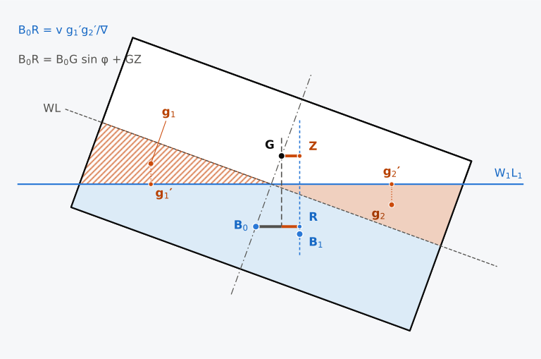
Figure 8.1 The wedges and the movement of B in a box section 12 m wide and 6 m deep at a draught of 3 m, KG = 4 m, heeled 20°, drawn with the water surface level and to scale. Emerged wedge hatched, immersed wedge shaded.
Historical note: Atwood and Vial du Clairbois
8.1.2 KN and the righting lever
Chapter 4 split the righting lever into KN, which depends on the hull, and KG sin φ, which depends on the loading, and found that KN equals KM sin φ at small heels (Sec. 4.4.2). Figure 8.2(a) shows why the split holds at any angle. The construction of Eq. (8.1) is made there about the keel point K instead of , on a box heeled to an angle φ and drawn with the water surface level, with the buoyancy acting upward along the vertical through the centre of buoyancy . N is again the foot of the perpendicular from K to this line, and KN is the lever of the buoyancy about K. Z is the foot of the perpendicular from G, and the vertical through G meets KN at X. GXNZ is a rectangle, so XN = GZ. In the right-angled triangle KXG the angle at G is the heel φ, so KX = KG sin φ. Since KN = KX + XN,
for G on the centreline5,8. The second expression is the horizontal distance of from K towards the low side, found by the rotation of a point in heel (Sec. 1.3.2) from the coordinates and of in the frame of the ship, measured from K; is negative when lies to starboard. Equation (8.2) holds at any heel, and at small heels it returns to GZ = GM sin φ.
In Fig. 8.2(b) the two parts are drawn for the Series 60 ship in its departure condition, heeled 75°. KG sin φ, 5.686 m, now exceeds KN, 5.493 m, so lies on the high side of G, and the negative lever, −0.193 m, heels the ship further.
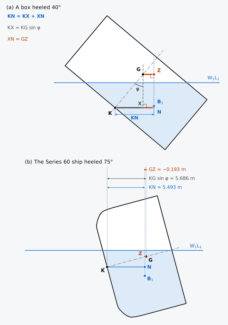
Figure 8.2 KN and the righting lever, drawn with the water surface level and to scale. (a) A box section 12 m wide and 6 m deep at a draught of 3 m, KG = 4 m, heeled 40°. (b) The Series 60 ship in its departure condition, 7707 t with KG = 5.887 m, heeled 75°; is that of the whole hull.
8.1.3 A box heeled beyond its deck edge
Because its sections are rectangles, a box allows the whole calculation to be done by hand. Chapter 4 used the wall-sided formula for a box section 12 m wide, floating at 3 m with KG = 4 m, up to the angle of 26.6° at which its deck edge goes under and its bilge comes out. Beyond that angle the immersed section is no longer a trapezium, and the formula no longer applies.
Example 8.1. A box heeled beyond its deck edge. A box barge has a rectangular section 12 m wide and 6 m deep. It floats at a draught of 3 m with KG = 4 m, so that KB = 1.5 m, BM = 4.0 m and GM = 1.5 m. Find KN and GZ when it is heeled 40° to starboard, and compare GZ with the wall-sided formula.
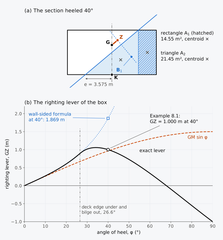
Figure 8.3 The box of Example 8.1. (a) The section heeled 40°, drawn in the frame of the ship. (b) Its righting lever, computed exactly, with the wall-sided formula and GM sin φ.
In Fig. 8.3(b) the lever of the box is plotted against the heel. Drawn for one displacement and one position of G, such a plot is the curve of righting levers, also called the curve of statical stability or the GZ curve4,5. The lever of the box is largest, 1.06 m, near 34°, and falls to zero near 68°, its angle of vanishing stability; beyond that angle the lever is negative and heels the box further.
8.1.4 Calculation for a ship’s hull
For a ship, the box calculation is made section by section. Each section of the hull is cut by the inclined waterline, and the area of the part below it and the moments of that area are found. These are integrated along the length with the rules of Chapter 2 to give the immersed volume and its centroid. The waterline is then raised or lowered by , where is the area of the inclined waterplane and the displaced volume, and the calculation is repeated until the two volumes agree5.
For the calculations of this chapter the Series 60 hull, 121.92 m between perpendiculars and 16.256 m in breadth, with its flat deck 9.754 m above the keel, is cut into 239 sections, 0.53 m apart from the end of the stern to the stem. Each section is a polygon of up to 482 points. The part of each polygon below the waterline is found exactly, and the sections are integrated along the length by the trapezoidal rule (Notes on the data). Chapter 4 used these sections, with the trim held at zero, to find the lever of this ship up to 40°.
8.1.5 Trim as the ship heels
At a large angle of heel the waterplane is no longer symmetric about the centreline, and the centre of buoyancy moves along the ship as well as across it5. With G fixed, the ship then trims until B is again in the vertical transverse plane through G. Programs for hydrostatic calculation therefore adjust both the draught and the trim at each angle of heel, until the buoyancy equals the weight and the trimming moments of weight and buoyancy balance9. A lever found in this way is said to be computed with the trim free. Before computers, KN was usually calculated at constant trim, with the ship on an even keel, although the trim that comes with the heel can change it considerably5. The IS Code recommends that hydrostatic and stability curves be calculated with the trim free10, and unless the trim is said to be held, the levers of this chapter are computed in this way.
For the Series 60 ship the effect is small but not negligible. In its departure condition, 7707 t with KG = 5.887 m, the ship floats practically level when upright. With the trim held at that value, B moves aft as the ship heels, by 0.95 m at 40°, because the wedge that goes under lies further aft, on the whole, than the wedge that comes out. Left free, the ship trims by the head until B is again in the vertical transverse plane through G: by 0.54 m at 30°, 0.79 m at 40° and 1.06 m at 60° (Fig. 8.4(a)). The trim reduces the lever by up to 0.9 cm, near 36°, and the largest lever falls from 0.538 m with the trim held to 0.529 m with it free, while the angle of vanishing stability hardly changes. In the arrival condition, 7236 t with KG = 6.129 m, the ship is already trimmed 0.77 m by the head when upright. With the trim held there, B again moves aft as the ship heels; left free, the ship trims further by the head, to 1.50 m at 40°. Its lever then falls by up to 1.1 cm, near 40°, and its largest lever by 1.0 cm (Fig. 8.4(b)).
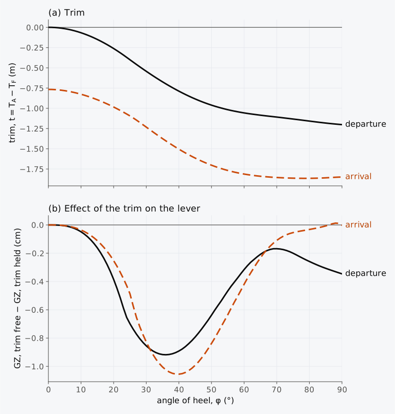
Figure 8.4 The Series 60 ship left free to trim as it heels: departure, 7707 t with KG = 5.887 m, and arrival, 7236 t with KG = 6.129 m. (a) The trim, negative by the head. (b) The lever with the trim free less the lever with the trim held at its upright value.
8.2 The curve of righting levers
8.2.1 Features of the curve
Computed on the whole hull at each angle of heel and drawn against the heel, the levers of one loading condition form the curve of righting levers of the ship. Multiplied by the displacement , the righting lever gives the righting moment, and the curve is sometimes drawn as a curve of righting moment instead9. A ship can have larger levers light than loaded and yet smaller righting moments, because loaded it is much heavier6. Several features of the curve describe the stability of the ship in its condition of loading4,9.
The slope at the origin. The slope of the curve at the origin is the metacentric height, because GZ = GM sin φ at small angles. A straight line from the origin to the point at φ = 1 rad (57.3°) whose height is GM is therefore tangent to the curve at the origin. Biran and López-Pulido recommend drawing it on every curve of righting levers as a check, and warn against the reverse, fitting a tangent to the curve and reading GM from it5. GM is found from KM − KG, and a value read from the curve is only an estimate.
The point of inflexion. At this point the curve stops bending upward and starts bending downward. It lies near the angle at which the deck edge goes under water or the bilge comes out; along much of the ship’s length this happens within a small band of angles4.
The maximum righting lever. The largest lever, , occurs at the angle . The largest righting moment, , is the largest constant heeling moment that the closed hull can withstand when the moment is applied gradually4; an opening that goes under at a smaller angle sets a lower limit. A smaller moment applied suddenly can capsize the ship, since it rolls past the angle at which the moments balance.
The angle of vanishing stability. At this angle, , the lever falls to zero again, at the end of the range of positive lever that begins upright4. Released from rest just below this angle, the closed hull initially rolls towards upright; exactly at it, the ship is in unstable equilibrium. An existing roll velocity or an earlier downflooding limit can prevent recovery.
The range of stability. This is the range of heel over which the lever is positive. Freeboard and reserve buoyancy are important factors in it4.
The stability rules also use an angle that is set by the openings in the ship. The IS Code defines the downflooding angle, , as the angle of heel at which openings in the hull, superstructures or deckhouses that cannot be closed weathertight are immersed10. Beyond it, water can enter the ship, and a curve computed for the intact, closed hull no longer describes the ship.
8.2.2 The curve of the Series 60 ship
Figure 8.5 shows the curve of the departure condition with its features. The ship displaces 7707 t with KG = 5.887 m and G on the centreline, and the curve is computed on the whole hull with the trim free. The metacentric height of the ship is 0.659 m, from KM = 6.546 m and KG, and the slope of the computed curve at the origin, found from the lever at 0.5°, gives 0.660 m. A line from the origin through the lever at 10°, 0.1218 m, rises by 0.698 m over one radian instead, because the curve bends upward from the start. The curve rises above its tangent at first and keeps bending upward until the deck edge amidships reaches the water at 23.1°, where its point of inflexion lies. Chapter 4 estimated this angle at 22.6° from the freeboard of the upright ship. At constant displacement, however, the ship rises a little as it heels; at 20° the water on its centreline amidships has fallen by 6 cm, and the edge goes under slightly later. The lever reaches its maximum, 0.529 m, at 37.0°, and falls to zero at 68.3°, the angle of vanishing stability. The largest righting moment is
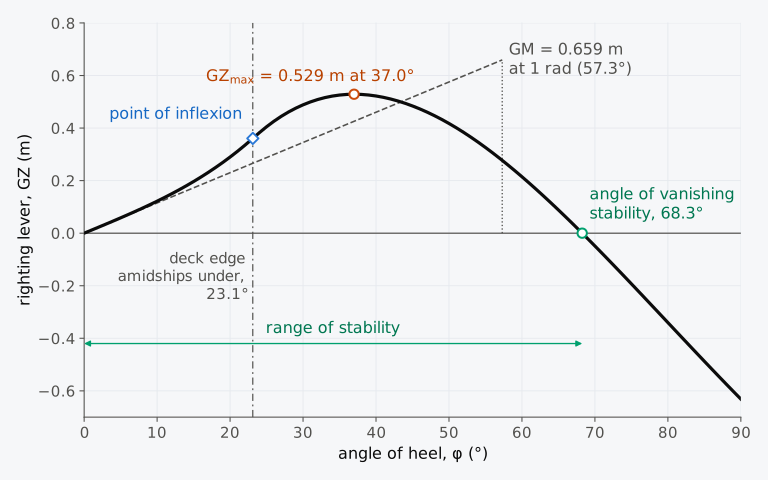
Figure 8.5 The curve of righting levers of the Series 60 ship in its departure condition, 7707 t with KG = 5.887 m, computed on the whole hull with the trim free.
8.2.3 The slope of the curve at any angle
At the origin the slope of the curve is GM. In the transverse construction, at any angle it is
where is the metacentre for the angle φ, the point at which the projected lines of action of the buoyancy at neighbouring angles cross, and is its distance above Z in that construction5. Upright, Z coincides with G and Eq. (8.3) gives GM. Where the metacentre for the angle lies above Z, the lever grows with the heel; at the maximum of the curve it lies at Z; beyond the maximum it lies below Z, and the lever falls. Chapter 4 traced the path of this metacentre for the Series 60 ship (Fig. 4.14). It rises as the ship heels until the deck edge goes under, and then falls. The slope of the curve grows and then shrinks as this metacentre rises and falls, so the point of inflexion lies close to the angle at which the deck edge goes under.
8.3 Cross curves of stability (KN curves)
8.3.1 The purpose of the cross curves
The righting lever of a ship changes with its loading. The displacement and the height of the centre of gravity differ from one loading condition to the next, and they also change during a voyage, as fuel and stores are used and ballast is taken in or pumped out. Between departure and arrival the Series 60 ship becomes 471 t lighter and its G rises by 0.242 m. In the Cougar Ace, the fuel used from the double-bottom tanks was one of the changes that left the ship unstable1. A lever computed for one position of G therefore serves only one loading condition9.
At a given displacement, heel and trim, the form of the hull determines the immersed volume, its centre of buoyancy and the line of action of the buoyancy through . Each height of G on the centreline then has its own lever to that line. Figure 8.6 shows this on the box of Example 8.1, 12 m wide and 6 m deep, floating at a draught of 3 m and heeled 40°, with G at , 1.5 m above the keel, and at , 4.0 m above it. The lever shortens as G rises, is zero at M′, where the line of action crosses the centreline 5.556 m above the keel, and is negative with G higher still.
As Chapter 4 noted, the lever with G imagined at the keel point K is KN, 3.571 m for the box, and it depends only on the form of the hull, the displacement, the heel and the trim. No ship has its centre of gravity at the keel, but the assumption removes the height of G from the calculation, and KN can then be computed from the lines before the ship is built5. The actual G enters afterwards, through KG sin φ in Eq. (8.2): = 3.571 − 1.5 sin 40° = 2.607 m, and = 3.571 − 4.0 sin 40° = 1.000 m.
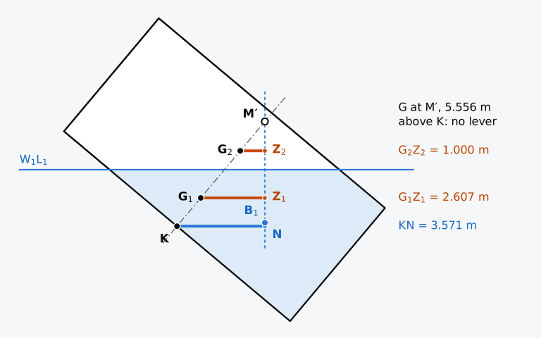
Figure 8.6 One heeled hull and several heights of G: the box of Example 8.1 heeled 40°, drawn with the water surface level and to scale.
KN is therefore computed once, for a range of displacements and a set of angles of heel, and set out in a table with a row for each displacement and a column for each angle. Each column, plotted against the displacement, gives one curve, and the curves for all the angles are the cross curves of stability, or KN curves5,8. Each row gives KN at every angle for one displacement; with its KG, this is all that a loading condition at that displacement needs.
Measured from the lowest point of the keel, KN is positive over the usual range of heel, and since G lies above K, KG sin φ is always subtracted5,9. In European texts, KN is often called the lever of stability of form, and KG sin φ the lever of stability of weight5. Read against the immersed volume, KN holds in water of any density4.
8.3.2 Computing the cross curves
Before computers, the cross curves were the main tool for calculating intact stability9, and the way they were computed made them practical by hand. A curve of righting levers is drawn at a fixed displacement for a range of heel, and a cross curve at a fixed heel for a range of displacement. At a fixed heel, a waterline drawn across the inclined sections at a guessed height cuts off some immersed volume, in general not the volume wanted, and finding the waterline of a given displacement at every angle needs repeated trials4. Instead, several parallel waterlines were drawn at each heel. For each, the immersed volume and its moment about the vertical through K were found section by section, and their quotient is KN at whatever displacement that waterline gives6,9:
where is the immersed part of the section at , whose area is , and the immersed volume. The points found at one heel, plotted against the displacement, trace the cross curve for that heel, and KN at any displacement between them follows by interpolation, without the waterline of that displacement ever being found. Animation 8.1 shows the waterlines of a range of displacements at 40° on the Series 60 hull, and the cross curve they trace.
Historical note: the curves by hand
In his textbook of 1899, E. L. Attwood described the methods then in use for curves of stability6. In Blom’s mechanical method the sections of the body plan were cut out of drawing paper and gummed together, once up to the upright waterline and once, a little above it, for the inclined waterline. The inclined set was trimmed parallel to its waterline until it weighed as much as the upright set, and its centre of gravity, found by hanging it from two points, gave the centre of buoyancy of the heeled ship. Barnes’s method, a system of tables introduced at the Institution of Naval Architects in 1861, was by then giving way to the integrator, an instrument that gave the area and the moment of a section as its pointer was passed round the outline6.
A computer program, by contrast, can search for the waterline at every heel. For the cross curves, is set at the of the ship floating upright, and the ship is left free to trim as it heels9. The angles are usually multiples of 10° or 15°; for small ships with low freeboard, steps of 5° or 10° are used9.
Animation 8.1 The cross curve of the Series 60 hull at 40°, traced from 2500 t to 10,000 t with the trim free. Above, the midship section in the frame of the ship, heeled 40° with the starboard side to the right, with the waterline at the displacement shown where it crosses that section, the centre of buoyancy B1 of the whole hull with the line of action of the buoyancy through it, and KN in orange from the keel point K to the foot N of the perpendicular on that line; a dotted line through K is parallel to it. Below, KN against the displacement, falling from 4.83 m to 3.96 m as the waterline rises and less of the hull stays above the water. The poster shows six of the waterlines together, at 2500 t, 4000 t, 5500 t, 7000 t, 8500 t and 10,000 t, each with its B1 joined to its N, and their six points on the curve. No sound; 9 s.
8.3.3 The cross curves of the Series 60 hull
Figure 8.7 shows the cross curves of the Series 60 hull from 2500 t to 10,000 t, and Table 8.1 lists them every 500 t from 3000 t to 9000 t. KN for a loading condition is read where a vertical line at its displacement crosses each curve, as on the dotted line of Fig. 8.7, at 7707 t in the departure condition5. The curves were computed about the keel point K, with G at the keel, KG = 0, and with the trim free. At each displacement the longitudinal position of G was taken equal to that of the centre of buoyancy of the ship floating upright and level, . KN computed with the KG of an actual condition differs a little, because the trim at which the heeled ship balances changes with KG. For the departure and arrival conditions, each at its own , the difference is at most 0.3 mm and 0.7 mm, so the height of G can be left out of the table. Its longitudinal position cannot. The table holds for the ship floating level when upright, as it does on departure. In the arrival condition, trimmed 0.77 m by the head, the levers read from it are too large by up to 1.1 cm. The trim that comes with the heel matters more at light displacements; at 3000 t, KN with the trim held exceeds KN with the trim free by up to 5.5 cm, at 60°. Table 8.1 also gives KM, from the hydrostatic curves of Chapter 7, for finding GM.
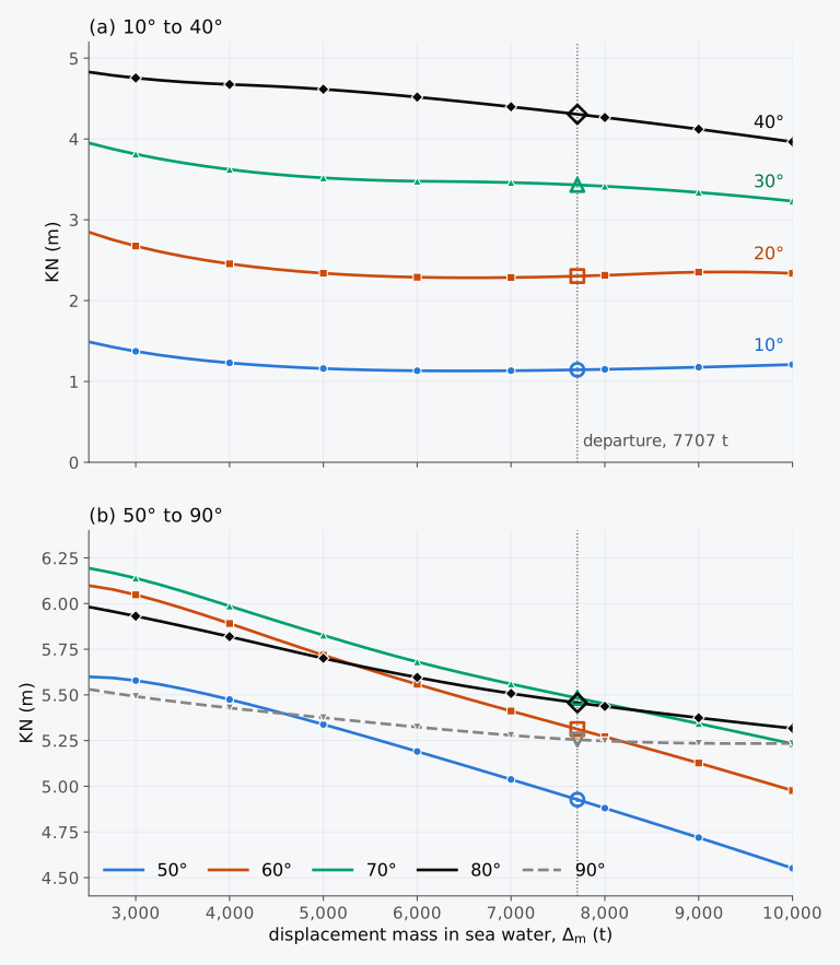
Figure 8.7 Cross curves of stability of the Series 60 hull every 10° of heel, with KG = 0 and the trim free. The open markers on the dotted line are KN at 7707 t, the departure displacement mass.
Table 8.1 Cross curves of stability of the Series 60 hull in sea water: KN (m) with KG = 0 and the trim free, being equal to of the ship floating upright and level, and KM (m) of the ship floating upright and level.
| (t) | KM | 5° | 10° | 20° | 30° | 40° | 50° | 60° | 70° | 80° | 90° |
|---|---|---|---|---|---|---|---|---|---|---|---|
| 3000 | 7.915 | 0.689 | 1.373 | 2.675 | 3.813 | 4.755 | 5.579 | 6.048 | 6.139 | 5.931 | 5.492 |
| 3500 | 7.406 | 0.646 | 1.289 | 2.549 | 3.705 | 4.706 | 5.534 | 5.974 | 6.067 | 5.877 | 5.459 |
| 4000 | 7.037 | 0.615 | 1.230 | 2.456 | 3.623 | 4.675 | 5.475 | 5.891 | 5.986 | 5.819 | 5.429 |
| 4500 | 6.786 | 0.593 | 1.188 | 2.387 | 3.561 | 4.650 | 5.409 | 5.803 | 5.905 | 5.759 | 5.402 |
| 5000 | 6.620 | 0.578 | 1.160 | 2.339 | 3.519 | 4.616 | 5.339 | 5.718 | 5.827 | 5.701 | 5.376 |
| 5500 | 6.516 | 0.569 | 1.142 | 2.307 | 3.492 | 4.571 | 5.266 | 5.636 | 5.751 | 5.646 | 5.350 |
| 6000 | 6.463 | 0.565 | 1.133 | 2.290 | 3.478 | 4.519 | 5.191 | 5.558 | 5.681 | 5.596 | 5.324 |
| 6500 | 6.454 | 0.564 | 1.130 | 2.283 | 3.472 | 4.461 | 5.115 | 5.484 | 5.618 | 5.550 | 5.301 |
| 7000 | 6.478 | 0.566 | 1.133 | 2.286 | 3.461 | 4.399 | 5.038 | 5.412 | 5.560 | 5.508 | 5.279 |
| 7500 | 6.523 | 0.569 | 1.140 | 2.297 | 3.442 | 4.334 | 4.960 | 5.342 | 5.505 | 5.471 | 5.261 |
| 8000 | 6.580 | 0.574 | 1.150 | 2.314 | 3.415 | 4.266 | 4.881 | 5.271 | 5.451 | 5.437 | 5.248 |
| 8500 | 6.650 | 0.581 | 1.162 | 2.336 | 3.381 | 4.195 | 4.800 | 5.200 | 5.398 | 5.405 | 5.240 |
| 9000 | 6.732 | 0.588 | 1.176 | 2.353 | 3.339 | 4.121 | 4.719 | 5.127 | 5.343 | 5.375 | 5.235 |
Up to 20°, KN follows KM sin φ roughly, and its curves dip to a shallow trough near 6500 t, where KM is least. From 30° upwards KN falls steadily as the displacement grows. A heavier ship has less freeboard, so its deck edge goes under at a smaller angle, and less of the hull stays above the water to give the lever at large angles.
8.3.4 Reading the cross curves for a loading condition
For a loading condition, the displacement and KG come from the weight table. KN is read from the cross curves at that displacement for each angle, and Eq. (8.2) gives the lever4. The largest lever and the angle of vanishing stability are then found from the levers at the tabulated angles.
Example 8.2. The departure condition from the cross curves. The Series 60 ship displaces 7707 t with KG = 5.887 m and G on the centreline. Using Table 8.1, find KM and GM, the righting lever at the tabulated angles, the largest lever and the angle at which it occurs, and the angle of vanishing stability.
Predict 8.1. On arrival the ship displaces 7236 t, 471 t less than at departure, with G 0.242 m higher, at KG = 6.129 m. Decide whether the largest righting lever and the angle of vanishing stability will then be larger or smaller than at departure, and which will change more in proportion.
The values of KN read in Example 8.2 lie on one surface, KN as a function of displacement and heel. A cross curve is a cut through this surface at one angle of heel, and the curve of KN against heel for a loading condition is a cut at its displacement5,6. Figure 8.8 shows the surface of the Series 60 hull with the cross curve at 40° and the cut at 7707 t, the departure displacement mass, which meet at the KN of 4.306 m read in Example 8.2.
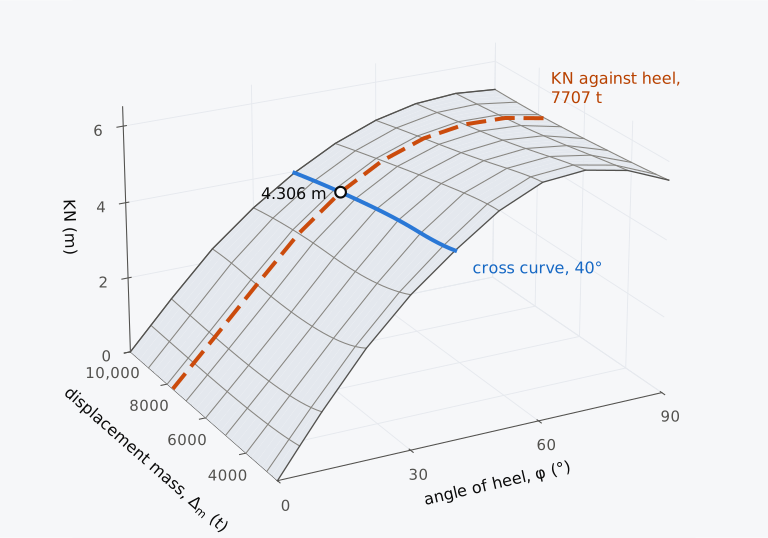
Figure 8.8 KN of the Series 60 hull as a surface over displacement mass and heel, with KG = 0 and the trim free. Solid, the cross curve at 40°; dashed, KN against heel at 7707 t.
Figure 8.9(a) shows this cut at 7707 t with KG sin φ, the other part of Eq. (8.2), for the departure condition. The lever is the gap between the curve of KN and the sine curve of KG sin φ, and it vanishes where they cross. Each point of KN from 10° to 90° is a crossing marked on the dotted line of Fig. 8.7, in the colour and shape of its curve.
The dotted curve KM sin φ is the lever about K that the ship would have if the metacentre stayed where it is when upright, as GM sin φ assumes (Sec. 4.7.1). It follows KN closely up to about 10°. The gap between the two curves equals GZ − GM sin φ and is 0.007 m at 10°, 0.158 m at 30° and −0.088 m at 50°. As in Sec. 4.9.1, KN = KM′ sin φ. In the departure condition KM′ is 6.862 m at 30°, above KM, 6.547 m, and it falls to 6.135 m at 60° and 5.835 m at 70°; the lever vanishes where M′ comes down to G. Figure 8.9(b) shows the curves of righting levers of the departure and arrival conditions.
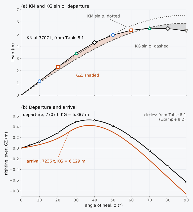
Figure 8.9 From the cross curves to the curve of righting levers. (a) KN at 7707 t from Table 8.1, with KG sin φ and KM sin φ for the departure condition; the lever is the shaded gap. (b) The levers of the departure and arrival conditions, computed on the whole hull; circles, Example 8.2.
Table 8.1 was computed for the ship floating level when upright. A ship that floats with a trim when upright has slightly different levers. On arrival the Series 60 ship is trimmed 0.77 m by the head, and the levers interpolated from Table 8.1 at that displacement are larger than those computed for the actual trim, by up to 1.1 cm at 30°. The IS Code recommends that the cross curves be prepared for the range of trim expected in normal operation10.
The lever can also be measured from an assumed centre of gravity on the centreline, often called the pole, placed either near the actual G or, for convenience, at the baseline, where it coincides with K5,9. If the pole P is at a height KP above the keel and the lever about it is PZ, the lever about the actual G is
which adds to PZ when G lies below P4. With the pole at K, KP = 0 and Eq. (8.4) becomes Eq. (8.2). Equations (8.1), (8.2) and (8.4) are thus one construction, made about , K or P: the lever about G is the lever about a point of the centreline, less the height of G above that point times sin φ. Cross curves drawn for a pole above K are called GZ cross curves, and they may carry a table of the correction for each metre of difference between KG and KP, equal to sin φ at each angle8.
8.4 Corrections to the righting lever
8.4.1 A change in the height of G
A change in the loading after the curve has been drawn can be applied to the curve as a correction, without reading the cross curves again. If G rises by at constant displacement and constant trim, KN does not change, and by Eq. (8.2) the lever is reduced by
The correction is a sine curve, zero upright and largest at 90°, so a rise of G reduces the lever at every angle, and most at large angles9. The slope at the origin falls by , the change in GM, and the angle of vanishing stability falls as well. For the Series 60 ship in its departure condition, raising G by 0.20 m lowers the largest lever from 0.529 m to 0.411 m and the angle of vanishing stability from 68.3° to 61.6°.
8.4.2 G off the centreline
As in Chapter 4, let G′ be the centre of gravity when it lies a distance GG′ to one side of the centreline. At a given trim, the lever for a heel towards that side is reduced by , and the lever for a heel the other way is increased by the same amount9. With G′ towards starboard, the righting lever about G′ (Chapter 4) for a heel to starboard follows from Eq. (8.2) as
Equilibria occur where this lever is zero, at angles φ where the lever with G on the centreline equals . A crossing with positive slope is stable; a zero alone does not establish stability or guarantee that the moving ship will settle there. At small angles, with GM sin φ for the lever, this gives Eq. (4.16), .
Example 8.3. A list at a moderate angle. In the departure condition of the Series 60 ship, 7707 t with GM = 0.659 m, 289 t of cargo is moved 4.0 m to starboard. With G on the centreline, the lever of the ship is 0.1356 m at 11° and 0.1499 m at 12°. Find the angle of list, first from Eq. (4.16) and then from the curve of righting levers.
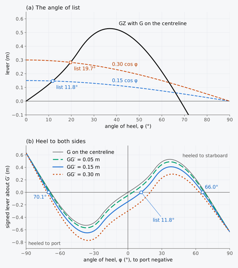
Figure 8.10 G off the centreline in the departure condition of the Series 60 ship, 7707 t with KG = 5.887 m. (a) The lever with G on the centreline and GG′ cos φ. (b) Levers about G′ for heels to both sides, heel to port negative; the lever is positive when lies to starboard of G′.
The lever that the ship keeps beyond the list matters more than the angle of list. All of it is reduced by , so an off-centre weight reduces the largest lever and the range of stability towards the low side. In Fig. 8.10(b) the levers are drawn for heels to both sides, with a heel to port negative and the lever taken, as in Chapter 4, as the signed horizontal distance of from G′, positive when lies to starboard of G′. Each curve rises through zero only at the list, where the ship rests. Heeled to port, the ship has more righting lever than with G on the centreline: with GG′ = 0.15 m the lever vanishes only at 70.1° to port, against 66.0° to starboard and 68.3° with G on the centreline. The weight shortens the range on the side of the list and lengthens it on the other.
The two corrections add. A weight moved both up and across reduces the lever by the rise of G times sin φ and by the movement of G towards the low side times cos φ9.
8.4.3 Free surfaces at large angles
Chapter 5 showed that a liquid with a free surface moves towards the low side as the ship heels, and that at small angles its effect is a virtual rise of G by the free surface correction . At large angles the IS Code allows the lever to be corrected in either of two ways: from the actual moment of the liquids, computed at each angle, or from the second moments of the free surfaces at zero heel, modified at each angle10. The actual moment of each tank follows from Eq. (5.9) or from the geometry of the tank itself. The simplest form of the second way treats the free surfaces as a rise of G at every angle and subtracts from the lever, as Eq. (8.5) does for a real rise of G. For a barge with tanks half full, Moore found this close to the direct calculation up to about 30°; beyond it, the direct calculation gave the larger loss of lever9.
Example 8.4. Free surfaces at 30°. In the departure condition of the Series 60 ship, 7707 t, four tanks are slack: fuel oil tank 3 starboard, the diesel oil and lubricating oil tanks, all three in the double bottom, and the fresh water tank in the aft peak. Their free surface moments at zero heel add up to 1021.2 t·m. Computed from the geometry of each tank, the heeling moments of their liquids at 30°, divided by g, are 43.5, 7.2, 1.7 and 41.7 t·m. Computed on the whole hull with the liquids frozen, the lever at 30° is 0.488 m. Find the lever at 30° corrected (a) by a virtual rise of G and (b) by the actual moments of the liquids.
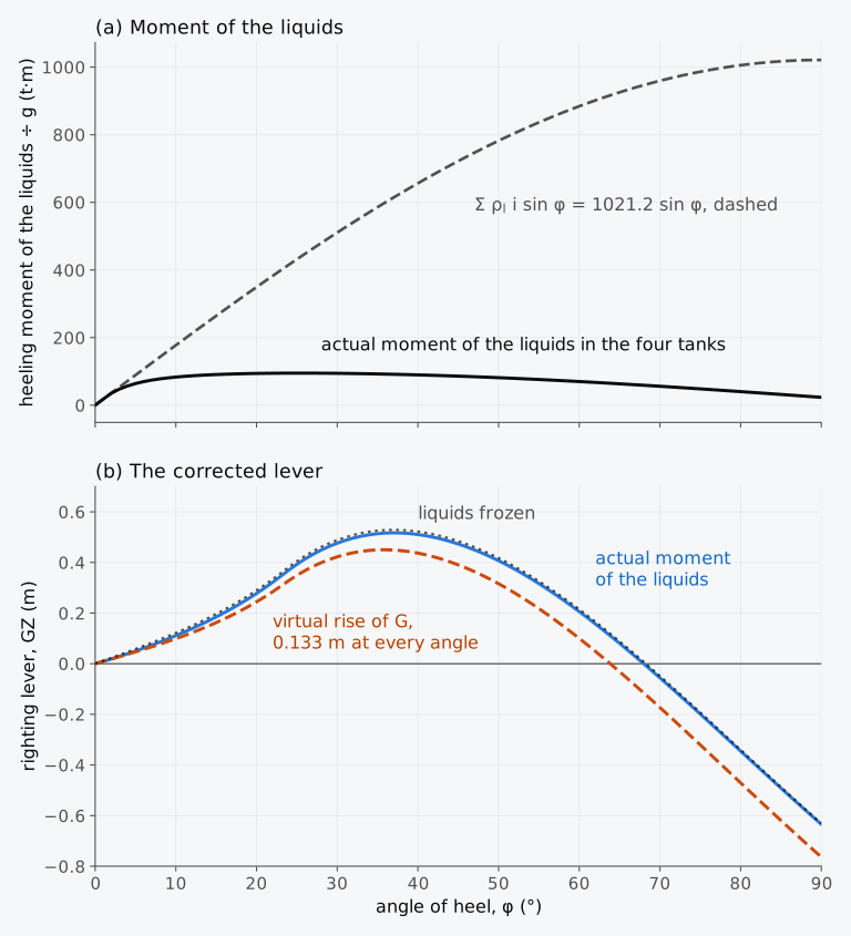
Figure 8.11 Free surfaces in the departure condition of the Series 60 ship, 7707 t with KG = 5.887 m. (a) The heeling moment of the liquids in the four slack tanks, divided by g, against the free surface moments times sin φ. (b) The lever with the liquids frozen and with the two corrections.
8.4.4 Righting lever calculator (Calculator 8.1)
Calculator 8.1 finds the curve of righting levers of the Series 60 ship from the KN curves of Table 8.1 for a displacement and KG of your choice. It works as Example 8.2 does, and it can also correct the lever for free surfaces, as a virtual rise of G, and for G off the centreline. Its figure carries the values of KN read on the cross curves, at a vertical line drawn at the displacement, to a plot of KN and KG sin φ against the heel, and then to the lever. A change in KG moves only the sine curve and the lever; a change in displacement moves the vertical line and the points of KN. Like the table, it takes KN with KG = 0 and the trim free, for the ship floating level when upright. For the loading conditions of the Series 60 ship the height of G changes KN by less than 1 mm, but in the arrival condition, trimmed 0.77 m by the head, the levers come out up to 1.1 cm too large.
8.5 The form above the water
8.5.1 Freeboard
GM depends on the hull below the waterline and on the height of G. The curve of righting levers at large angles depends also on the hull above the waterline, as it goes under water when the ship heels. Chapter 4 showed this with HMS Captain and HMS Monarch, two ships with nearly equal metacentric heights whose curves parted beyond about 20° because Monarch had much more freeboard than Captain. Figure 8.12(a) shows the effect of freeboard on the Series 60 hull, with its flat deck lowered and raised by 1 m and the displacement and KG of the departure condition kept; only the depth of the hull changes the freeboard here, not the loading.
Up to the angle at which the lowest of the three decks reaches the water, the three curves coincide, because the three hulls are identical below that deck. With 2.39 m of freeboard, the deck edge goes under at about 17°, the lever peaks at 0.289 m at 24.2° and vanishes at 46.2°. With 3.39 m, as built, the peak is 0.529 m at 37.0° and the lever vanishes at 68.3°. With 4.39 m the deck edge stays clear to about 29°, and the lever rises to 0.824 m at 46.9° and vanishes only at 88.4°. One metre of freeboard either way changes the largest lever by about half and the range of stability by about 20°, while GM does not change at all.
Raising the deck of a real ship also raises its centre of gravity, by the weight of the added structure and of everything on and above the deck. The net effect of a greater depth is a smaller lever until the original deck edge goes under, and a much larger lever beyond, provided that the gain in buoyancy outweighs the rise of G9.
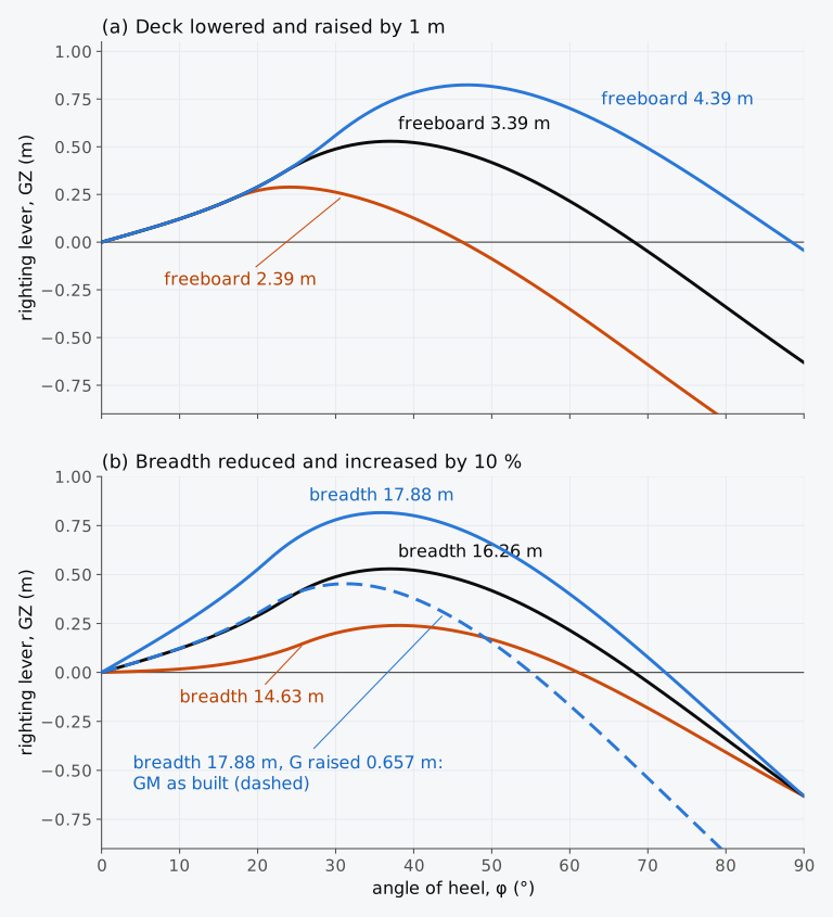
Figure 8.12 The form above the water and the levers of the Series 60 ship. (a) The deck lowered and raised by 1 m, at the displacement and KG of the departure condition. (b) The breadth changed by 10 %, at the draught and KG of the departure condition; dashed, the wide hull with the GM of the hull as built.
8.5.2 Breadth
A change in breadth acts differently from a change in freeboard, because it changes GM as well. Figure 8.12(b) shows the hull with every half-breadth multiplied by 0.9 and by 1.1, at the draught, depth, freeboard and KG of the departure condition. Every immersed area changes in proportion to the breadth, and so does the displacement mass, to 6936 t and 8478 t. KB does not change, while the second moment of the waterplane changes as the cube of the breadth, so BM changes as its square, by the factors 0.81 and 1.21, from 3.13 m to 2.53 m and 3.79 m. GM, from the slope of the lever at 0.5°, falls from 0.660 m to 0.065 m on the narrow hull and rises to 1.317 m on the wide hull. On the wide hull the deck edge lies at the original height but further out, and it goes under earlier, at about 20.7° against 22.6°, estimated from the upright freeboard. A wider hull in this family at a given draught and KG nevertheless has a larger lever at every angle short of 90° and a longer range of stability, the usual effect of a greater breadth8. The largest lever is 0.816 m on the wide hull and 0.240 m on the narrow hull, against 0.529 m, and the angle of vanishing stability 72.2° and 61.1°, against 68.3°. At 90° the three levers meet, because KN there is the height of the centroid of the immersed part, which a change in breadth does not move.
With draught and freeboard kept, a wider ship loses stability at large angles only when the gain in GM is spent on a higher G. If G is raised by 0.657 m, to give the wide hull the GM of the hull as built, the lever falls by 0.657 sin φ at every angle, by Eq. (8.5). The wide hull then has the larger lever only up to about 25°; its largest lever is 0.453 m, at 31.3°, and its lever vanishes at 55.0° (the dashed curve of Fig. 8.12(b)).
8.5.3 Flare, superstructures and openings
Flare above the waterline, a hull that widens upward, acts much like a greater breadth, but it is felt only at larger angles, when the flared part goes under. Tumblehome, a hull that narrows upward, reduces the lever at large angles. Neither changes GM, apart from a small change in the height of G from the structure itself9.
In this chapter the hull is treated as closed up to its deck, and the cross curves of a ship are usually computed for a watertight envelope of bottom, sides and weather deck. Superstructures and deckhouses with watertight sides, ends and tops can add to the lever, but they are often left out, because some of their openings may not be closed in service even if they are meant to be watertight9. Under the IS Code, enclosed superstructures that meet the conditions of the International Convention on Load Lines may be counted, and some deckhouses under further conditions. A superstructure or deckhouse that is not enclosed can be counted up to the angle at which its openings are flooded; at that angle the curve shows a step, and beyond it the flooded space is left out. If flooding through an opening would sink the ship, the IS Code ends the curve at the angle at which that opening goes under10.
8.5.4 Exploring the form (Explorer 8.1)
In Explorer 8.1 you can change the breadth, depth and draught of a box barge, the height of its centre of gravity and its distance GG′ from the centreline, and watch the effect on its curve of righting levers; the section is drawn at the heel you choose. The levers are computed exactly for the box section, as in Example 8.1, and the wall-sided formula is drawn up to the angle at which it stops holding. Try a deep, narrow box with G high, and then a wide, shallow box with an equal GM.
8.6 Negative metacentric height at large angles
8.6.1 Loll and the curve of righting levers
Chapter 4 found the angle of loll of a wall-sided ship from Eq. (4.18), . From the whole curve of righting levers we can see how much stability the lolled ship has left. In Fig. 8.13(a) the Series 60 ship has the displacement of its departure condition, with G raised to 6.696 m, 0.15 m above M, and a GM of −0.15 m. The lever is negative up to 18.1°, the angle of loll, where it rises through zero; the wall-sided formula puts the loll at 17.2°. Beyond the loll the lever is positive, but it reaches only 0.084 m, at 29.8°, and it vanishes at 40.1°. The lolled ship is stable, but only over the 22° beyond its loll, and a steady heeling moment of more than 6300 kN·m, a sixth of what the ship could withstand upright with its departure G, would capsize it. If G were also 0.2 m off the centreline, the lever towards that side would be negative at every angle, and the ship would capsize without any heeling moment at all.
The slope of the curve at the loll is 0.324 m per radian. Equation (4.19), with the computed angle of loll, gives = 0.30/cos 18.1° = 0.316 m: about the loll the ship behaves as if it had a positive metacentric height twice as large as its negative GM upright4. Whether a ship with a small negative GM can find a stable heeled equilibrium depends on the whole curve and on whether the hull remains watertight. Upward curvature near the origin, as in this Series 60 example, can lead to a zero crossing with positive slope and hence an angle of loll; downward curvature gives no such equilibrium near the upright. Neither shape alone settles the outcome, and the curve must be followed far enough to find a stable crossing before flooding or another limit intervenes9.
8.6.2 The Cougar Ace
With the curve of righting levers in hand, we can return to the Cougar Ace. The reports of the casualty give neither the metacentric height of the ship after the ballast exchange nor its curve of righting levers, so that curve cannot be drawn here. They do establish that the ship became unstable and that it came to rest heeled about 80° to port1. In the static picture, with the hull closed and no other moment acting, a ship comes to rest where its lever is zero and rising with the heel. If the lever of the Cougar Ace held it there, that lever rose through zero at about 80°, as the lever of Fig. 8.13(a) does at 18.1°. Water that came in, cargo that shifted and the wind could also have played a part, and the reports do not separate them.
Whether such a second position exists depends on the hull above the original waterline. Figure 8.13(b) shows the Series 60 hull with its sides continued vertically and its deck raised to 16.0 m above the keel, two and a half times its draught, as an example of a hull closed far above the water. With GM = −0.15 m this hull lolls to 18.1°, as before, because the added hull is still out of the water there. Beyond the loll, however, its lever keeps growing, to 2.11 m at 91°, and it is still positive at 120°. With G raised further, to GM = −1.0 m, the hull with its deck at 9.754 m capsizes, but the high hull comes to rest at 43.9°. If G is also 0.2 m to starboard, as after uneven ballasting, it lies at 47.8° to that side. Unstable upright, the high hull is held at a large angle by the buoyancy of the hull added above the original deck, but only while that part stays watertight; once an opening goes under, water enters, and the downflooding angle ends the curve. The reports do not say what held the Cougar Ace at about 80°, and its curve may have had a different shape.
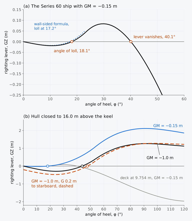
Figure 8.13 Negative metacentric height at large angles. (a) The Series 60 ship with GM = −0.15 m, with the wall-sided estimate of the loll. (b) The hull closed by vertical sides to a deck 16.0 m above the keel, an illustrative hull, not the Cougar Ace; grey, the deck at 9.754 m with GM = −0.15 m.
8.7 Stability at large angles in industry today
This section describes practice in 2026.
Cross curves in the stability information. Among the contents that the IS Code recommends for a stability booklet are hydrostatic curves or tables and cross curves of stability for the ranges of displacement and trim expected in normal operation, the cross curves calculated on a free-trimming basis, and plans that show the downflooding angles10. The IS Code also asks for the curves to include the volume up to the upper surface of any deck sheathing, the appendages and the sea chests, and, where the ship is not symmetric about its centreline, for the less favourable of the two curves of righting levers to be used10. The Code’s criteria on the properties of the curve of righting levers concern the areas under it, the lever at angles of 30° or more and the angle of its maximum, together with the initial GM10.
Methods in software. A stability instrument on board either uses only the data of the approved stability booklet, which include the cross curves, or computes the levers from a model of the hull form, and the IS Code sets separate tolerances for the two10. Among their examples of the data programmed into an instrument, IMO’s guidelines for the approval of stability instruments, MSC.1/Circ.1229, give the cross curves, as values of KN or of an alternative lever, at a set of angles of heel and trim against the displacement11. Grinnaert, Billard and Laurens describe a solver that computes from the hull form. In it the hull is a volume mesh of tetrahedra, prisms and hexahedra, built from the stations and cut by the waterplane. For a curve of righting levers the heel is fixed at each angle, and the sinkage and trim are found by successive corrections. In their ferry example, their second solution method meets the stated residual limits in one or two iterations. The paper reports this for that example and method, and does not claim it for every hull or loading12. The sources consulted for this section describe no format for exchanging cross curves other than the tables of the stability booklet.
Recent developments. Programs can also compute the cross curves of a ship in waves5. The interim guidelines on second generation intact stability criteria, MSC.1/Circ.1627 of December 2020 (Sec. 7.8), use such calculations in their second level of assessment for parametric roll. That level offers two alternative checks, either of which can establish non-vulnerability under the guidelines. One uses the variation of metacentric height in a set of waves, found by hydrostatic calculations, together with the ship’s speed. The other calculates roll in the time domain, with the righting lever computed in waves, and uses the weighted fraction of cases in which a roll of 25° is exceeded13,14.
8.8 From the righting lever to heeling moments
With the curve of righting levers of any loading drawn from the KN curves, we know the righting moment that the ship can supply at each angle of heel. Whether the ship heels to a dangerous angle depends also on the moments that act on it. A steady wind, a turn at speed, a load lifted over the side or passengers crowding to one side each produce a heeling moment that itself changes with the heel. Equal heeling and righting moments identify a possible equilibrium; for it to be stable, a further small heel must produce a net restoring moment. Even then, a moving ship need not stop at that angle: inertia carries it past the equilibrium, and damping is needed for its motion to settle. The work done against the righting moment as the heel grows is the area under the righting-moment curve, with angles in radians; equivalently, it is the area under the GZ curve multiplied by the ship’s weight. In Chapter 9 we will compute these heeling moments, compare them with the righting moment and use the areas under the curves to judge the dynamic stability of the ship, as the weather criterion of the IS Code does. We will also follow the righting lever into waves, where it changes as crests and troughs pass along the ship.
Summary
- At large angles of heel the righting lever must be computed from the whole immersed hull, at the waterline that gives the displacement at each angle. GM sin φ, the lever that the ship would have if the metacentre stayed where it is when upright, holds only at small angles, and the wall-sided formula only until the deck edge goes under or the bilge comes out. Atwood’s formula, Eq. (8.1), gives the lever from the wedges between the upright and the inclined waterlines: the movement of B parallel to the waterline less G sin φ.
- The split of the lever into KN, which depends on the hull, and KG sin φ, which depends on the loading, holds at any angle: GZ = KN − KG sin φ, Eq. (8.2). KN is the distance from the keel point K to the line of action of the buoyancy, , and at small angles it is KM sin φ.
- As a ship heels, B moves along it, and with the trim free the ship trims. For the Series 60 ship this lowers the lever by up to about 1 cm in its two loading conditions.
- The curve of righting levers has its slope GM at the origin and at any angle, Eq. (8.3), a point of inflexion near the angle at which the deck edge goes under, a maximum lever and its angle, and an angle of vanishing stability that ends the range of stability. The downflooding angle limits the part of the curve that can be used.
- KN is the lever that the ship would have with G at the keel. At a given displacement, heel and trim the form of the hull determines and its line of action, and each height of G has its own lever to that line; with G imagined at K, the height of G leaves the calculation. The cross curves of stability, or KN curves, give KN against displacement for a set of angles. Each column of their table is one curve. The same table can serve different loadings of the same hull, provided its trim and other assumptions apply; displacement and KG are the starting inputs, with off-centre G and free surfaces treated separately. By hand, each curve was traced at a fixed heel through several parallel waterlines, without the waterline of a given displacement ever being found. Computed with the trim free, as the IS Code recommends, they hold strictly for the position of G assumed in computing them, here KG = 0 and of the ship upright and level. The height of G costs the Series 60 conditions less than 1 mm; the trim costs more, and in the arrival condition, trimmed 0.77 m by the head, the levers read from Table 8.1 are up to 1.1 cm too large. With an assumed pole P the lever is PZ − (KG − KP) sin φ, Eq. (8.4).
- At constant displacement and trim, a rise of G reduces the lever by δKG sin φ, Eq. (8.5), and G off the centreline by GG′ cos φ towards that side, Eq. (8.6); a weight moved up and across reduces it by the sum of the two. Where the lever grows faster than GM sin φ, the ship lists less than the small-angle formula gives. An off-centre weight shortens the range of stability on the side of the list and lengthens it on the other.
- Free surfaces can be taken as a virtual rise of G or from the actual moments of the liquids. For the nearly full tanks of the Series 60 ship the second is much smaller; for a barge with tanks half full, the actual moments can exceed the virtual rise beyond about 30°.
- The curve at large angles depends on the form above the water. Increasing freeboard while keeping the upright immersed form and KG unchanged leaves GM unchanged but extends the lever and the range beyond the angle at which the deck edge goes under. A greater breadth at a given draught raises the lever and lengthens the range while G is kept, although the deck edge goes under earlier; spent on a higher G at equal GM, it shortens the range.
- A ship with a negative GM may loll to a stable angle or capsize, depending on its curve. A hull that is closed far above the water can hold a ship that is unstable upright at a large angle of heel.
Notes on the data
The Cougar Ace. The particulars of the ship, the ballast exchange and its outcome are from the summary of the flag State’s investigation that Singapore submitted to IMO1. The number of vehicles is from the Alaska Department of Environmental Conservation2, and the state of the ship three days after the casualty from The Maritime Executive3. The Department dates the crew’s first report of the list to 23 July 2006, and the flag State’s summary dates the casualty to 24 July; the difference may come from time zones or the date line. None of the sources gives the metacentric height of the ship at the time of the casualty, its lines or its curve of righting levers, and no data of the Cougar Ace are used in the calculations of this chapter.
The calculations on the Series 60 hull. The levers are computed by scripts/heel3d.py on the surface of Chapter 1, cut into sections 0.53 m apart; each section is a polygon through the surface at 241 heights from the keel to the flat deck 9.754 m above it (1.5 times the design draught, where Todd’s offsets end). For a heel φ and a trim angle θ the water surface is a plane, and the part of each section below it is found exactly from the polygon; the sections are integrated along the length by the trapezoidal rule. The waterline is found by a root search, and with the trim free, the trim is that at which B lies in the vertical transverse plane through G. The values are moulded, in sea water of density 1.025 t/m³, without appendages, sheer, camber or superstructures. The deck edge amidships is at a half-breadth of 8.128 m.
The loading conditions. The departure and arrival conditions are those of Chapters 3 to 5, with G on the centreline: 7707 t with KG = 5.887 m, practically level when upright, and 7236 t with KG = 6.129 m, trimmed 0.77 m by the head. Except in Sec. 8.4.3 the liquids in the tanks are treated as frozen; the free surface moments of the slack tanks are 1021.2 t·m on departure and 1385.0 t·m on arrival. For the cross curves, G is put at the keel point at each displacement, with equal to of the ship floating upright and level. With the trim free, KN computed with the KG of the departure condition, 5.887 m, differs from KN with KG = 0 by at most 0.3 mm over the angles of Table 8.1, and with the 6.129 m of the arrival condition by at most 0.7 mm. The surface of Fig. 8.8 joins the cross curves, computed every 250 t from 2500 t to 10,000 t, by straight lines between 0° and the angles of Table 8.1, and its cut at 7707 t is interpolated linearly between the curves at 7500 t and 7750 t. KM is read from the hydrostatic curves of Chapter 7. The free surfaces of Sec. 8.4.3 are those of the slack tanks of the departure condition in Chapter 5: the double-bottom tanks as rectangular boxes at their positions, and the aft peak as the part of the hull surface between the AP, the bulkhead 9.0 m forward of it and its flats 3.0 m and 8.0 m above the keel. The liquid in each tank is found below a plane parallel to the water surface at the ship’s heel and trim; its movement along the ship is not allowed to change the trim.
The modified hulls. The hull with its deck lowered is the Series 60 surface cut 1 m lower. The hulls with their decks raised continue the sides vertically from the half-breadths at 9.754 m, to 10.754 m in Fig. 8.12(a) and to 16.0 m in Fig. 8.13(b). The hulls of Fig. 8.12(b) have every half-breadth multiplied by 0.9 or 1.1; they float at the draught of the departure condition, 6.367 m, and displace 6936 t and 8478 t. In each case KG is that of the departure condition, or of the stated GM; on the dashed curve of Fig. 8.12(b) it is 0.657 m higher, the gain in GM of the wide hull, found as for the conditions from the slope of its lever at 0.5°. is that of the departure condition, except on the hulls of Fig. 8.12(b), where it equals of the hull floating upright and level.
Explorer 8.1 and Calculator 8.1. The explorer computes the levers of a box section exactly, every degree from 0° to 180°, finding the waterline by bisection. The calculator reads Table 8.1 as printed, interpolates KM and KN linearly in displacement to the millimetre, and finds the largest lever by a parabola through the largest tabulated value and its two neighbours, and the angles at which the lever changes sign by straight lines between the tabulated angles, as in Example 8.2.
Exercises
Under each exercise, “Show answers” opens its short answers and “Show full solution” its worked solution. Unless stated otherwise the water is sea water of density 1.025 t/m³, the draughts are moulded and G is on the centreline.
8.1 A box barge has a rectangular section 12 m wide and 6 m deep and floats at a draught of 3 m with KG = 4 m. Find KN and GZ when it is heeled (a) 60° and (b) 90°. (c) Between which angles does its angle of vanishing stability lie? (d) At what height of G would the lever at 90° be zero? Predict, before calculating, whether 90° is then the angle of vanishing stability, and where that angle moves if G is 1 cm higher or 1 cm lower; Explorer 8.1 can check the prediction.
8.2 A box barge 10 m wide and 5 m deep floats at a draught of 2 m with KG = 3.2 m. (a) Up to what angle does the wall-sided formula hold, and what ends its validity? (b) Find GM and the righting lever at 20°.
8.3 The box barge of Exercise 8.1 (12 m wide, 6 m deep, draught 3 m, KG = 4 m) is heeled 20°. Find the area of each wedge per metre of length, the distance between their centroids measured along the inclined waterline, and the righting lever by Atwood’s formula, Eq. (8.1).
8.4 The cross curves of a ship are drawn for a pole P 6.0 m above the keel. At the displacement of the ship they give PZ = 0.42 m at 30° and 0.61 m at 45°. The KG of the ship is 6.4 m. Find GZ at the two angles, and the values of KN that cross curves with the pole at the keel would give.
8.5 On arrival the Series 60 ship displaces 7236 t with KG = 6.129 m. Using Table 8.1, find (a) KM and GM, (b) the righting lever at 40°, 50°, 60° and 70°, and (c) the angle of vanishing stability by a straight line between the tabulated angles. (d) Compare the levers of (b) with GM sin φ at the four angles, and explain where and why they differ.
8.6 In Example 8.2 the departure condition of the Series 60 ship, 7707 t with KG = 5.887 m, has a lever of 0.215 m at 60°. How far could G rise before the angle of vanishing stability falls to 60°?
8.7 In the departure condition of the Series 60 ship, 7707 t with GM = 0.659 m, a mass of 100 t is moved 10 m to starboard. With G on the centreline the lever is 0.1218 m at 10°, 0.1356 m at 11° and 0.522 m at 40°. Find (a) the transverse movement of G, (b) the angle of list from Eq. (4.16) and (c) from the curve, and (d) the lever that remains at 40° towards starboard.
8.8 In the departure condition the Series 60 ship displaces 7707 t with KG = 5.887 m, and its levers, found from Table 8.1, are 0.522 m at 40°, 0.215 m at 60° and −0.049 m at 70°. The free surface moments of the slack tanks add up to 1021.2 t·m. Taking the free surfaces as a virtual rise of G, correct the three levers, and find the angle of vanishing stability by a straight line between 60° and 70°.
8.9 In the departure condition the Series 60 ship displaces 7707 t with KG = 5.887 m, and its levers, found from Table 8.1, are 0.291 m at 20° and 0.487 m at 30°. A steady heeling moment of 25,000 kN·m, which does not change with the heel, is applied gradually to the ship. Ignore downflooding. (a) Find the heeling lever. (b) Using a straight line between the two levers, find the stable equilibrium angle. (c) What is the largest steady heeling moment of this kind that the ship can withstand, with its largest lever of 0.529 m?
8.10 G of the Series 60 ship is raised until GM = −0.10 m at a displacement mass of 7707 t, where BM = 3.129 m. Find the angle of loll from Eq. (4.18) and the metacentric height about the loll from Eq. (4.19).
8.11 The Series 60 ship floats in fresh water of density 1.000 t/m³ at a displacement mass of 7317 t. At what displacement mass should Table 8.1, computed for sea water, be read, and what is KN at 40°?
8.12 With the trim held at its upright value, which is practically zero, the centre of buoyancy of the Series 60 ship in its departure condition, 7707 t, moves 0.95 m aft when the ship is heeled 40°. Estimate the trim that the ship takes when left free, using the MCT 1 cm of the upright ship, 86.87 t·m/cm. Is it trimmed by the head or by the stern?
8.13 The Series 60 hull with its deck raised to 16.0 m, at a displacement mass of 7707 t with GM = −1.0 m and G on the centreline, has a lever of −0.0258 m at 43°, 0.0042 m at 44°, 0.1050 m at 47° and 0.1423 m at 48°. Find the stable equilibrium angle (a) with G on the centreline and (b) with G 0.2 m to starboard.
8.14 A box barge 12 m wide and 6 m deep is heeled 30°. Three parallel waterlines, drawn in the frame of the box, cross its centreline 2.0 m, 2.5 m and 3.0 m above the keel. (a) For each waterline, find the immersed area of the section per metre of length and KN. (b) The barge displaces the volume that it displaces floating upright at a draught of 2.5 m. Treating the results of (a) as points of the cross curve at 30°, find its KN at 30° by linear interpolation between the two nearest points. (c) Find the height at which the waterline of that displacement crosses the centreline at 30°, and KN there.
Symbols introduced in this chapter
Symbols defined in earlier chapters, among them φ, θ, , Z, M, M′, N, GZ, GM, KB, BM, KM, KN, KG, GG′, G′, Z′, G′Z′, , , , , , , , , , , and , keep their meaning.
| Symbol | Meaning | Unit |
|---|---|---|
| , | feet of the perpendiculars from the centroids and of the wedges to the inclined waterline | – |
| centre of buoyancy of the upright ship | – | |
| R | foot of the perpendicular from to the line of action of the buoyancy through | – |
| X | point at which the vertical through G meets KN | – |
| , | coordinates of in the frame of the ship, to port and above the keel ( as in Chapter 1) | m |
| , | distance to starboard from the centreline in a section, , and that of | m |
| distance from the centreline at which the inclined waterline meets the deck and the bottom of a half-immersed box | m | |
| , | areas of the rectangle and the triangle into which the immersed box section is split | m² |
| immersed volume below a trial waterline | m³ | |
| , | largest righting lever, and the angle at which it occurs | m, ° |
| angle of vanishing stability | ° | |
| downflooding angle | ° | |
| metacentre for the angle φ | – | |
| , , , | two heights of G in Fig. 8.6, and the feet of the perpendiculars from them to the line of action of the buoyancy | – |
| , | immersed part of the section at , whose area is ; immersed area of a box section per metre of length | –, m² |
| , , , | lever at 40°, and the coefficients and variable of the parabola GZ = + + , with | m, m, m, – |
| P, KP, PZ | an assumed pole, its height above the keel, and the lever about it | –, m, m |
| , | rise of G, and the reduction of the righting lever that it causes | m |
| height at which a waterline crosses the centreline of a box section | m |
Corrections
Corrections to version 1.0, released on 3 November 2026, with their dates.
- 5 November 2026. The prologue says, as the cited report does, that the chief officer’s estimate of a metacentric height of 0.5 m in the worst case is known from the master’s account.
- 5 November 2026. Sec. 8.1.1 says that Atwood’s formula is named after the mathematician George Atwood, not after E. L. Attwood, the author of the textbook cited for the construction.
References
- Singapore. (2007, April 2). Information concerning the listing of the vessel “Cougar Ace” (FSI 15/6/2). International Maritime Organization, Sub-Committee on Flag State Implementation. Retrieved October 11, 2026, from https://maritimesafetyinnovationlab.org/wp-content/uploads/2019/08/IMO-Cougar-Ace-summary-report-2006_07.pdf Cited: ↑ annex, particulars and paras. 1–2 · ↑ annex, paras. 1–2 · ↑ annex, paras. 2–3 · ↑ annex, para. 4 · ↑ annex, paras. 1 and 5 · ↑ annex, para. 1 · ↑ annex, para. 6 · ↑ annex, para. 6 · ↑ annex, paras. 4 and 6 · ↑
- Alaska Department of Environmental Conservation. (2006). M/V Cougar Ace [Spill response archive]. Retrieved October 11, 2026, from https://dec.alaska.gov/spar/ppr/spill-information/response/2006/18-cougar Cited: ↑ · ↑
- The Maritime Executive. (2006, July 27). Cougar Ace remains afloat but listing. The Maritime Executive. Retrieved October 11, 2026, from https://maritime-executive.com/article/2006-07-27cougar-ace-remains-afloat-but-listing Cited: ↑ · ↑
- Tupper, E. C. (2013). Introduction to naval architecture (5th ed.). Butterworth-Heinemann. Cited: ↑ pp. 73–74 · ↑ p. 74 · ↑ p. 76 · ↑ p. 79 · ↑ p. 79 · ↑ p. 79 · ↑ p. 79 · ↑ p. 79 · ↑ pp. 77–78 · ↑ p. 77 · ↑ p. 78 · ↑ p. 78 · ↑ p. 76
- Biran, A., & López-Pulido, R. (2014). Ship hydrostatics and stability (2nd ed.). Butterworth-Heinemann. Cited: ↑ p. 117 · ↑ p. 118 · ↑ p. 120 · ↑ p. 351 · ↑ pp. 122–123 · ↑ pp. 122–123 · ↑ p. 122 · ↑ p. 122 · ↑ p. 118 · ↑ p. 119 · ↑ p. 119 · ↑ p. 118 · ↑ p. 119 · ↑ p. 125 · ↑ p. 119 · ↑ p. 123
- Attwood, E. L. (1899). Text-book of theoretical naval architecture. Longmans, Green, and Co. (Public domain.) Cited: ↑ pp. 158–159 · ↑ pp. 164–165 · ↑ pp. 181–182 · ↑ pp. 168–170 · ↑ pp. 177–179 · ↑ p. 182
- Nowacki, H., & Ferreiro, L. D. (2003). Historical roots of the theory of hydrostatic stability of ships. In Proceedings of the 8th International Conference on the Stability of Ships and Ocean Vehicles (STAB 2003) (pp. 1–30). Escuela Técnica Superior de Ingenieros Navales. Cited: ↑ p. 26
- Barrass, C. B., & Derrett, D. R. (2006). Ship stability for masters and mates (6th ed.). Butterworth-Heinemann. Cited: ↑ p. 176 · ↑ p. 176 · ↑ pp. 172–174 · ↑ pp. 233–234
- Moore, C. S. (2010). Intact stability (J. R. Paulling, Ed.; Principles of Naval Architecture Series). Society of Naval Architects and Marine Engineers. Cited: ↑ p. 19 · ↑ p. 18 · ↑ pp. 22–23 · ↑ p. 19 · ↑ p. 20 · ↑ p. 19 · ↑ p. 19 · ↑ p. 19 · ↑ p. 20 · ↑ p. 19 · ↑ p. 20 · ↑ p. 18 · ↑ p. 38 · ↑ p. 34 · ↑ pp. 20–21 · ↑ p. 21 · ↑ pp. 18–19 · ↑ pp. 23–24
- IMO. (2020b). International Code on Intact Stability, 2008 (2020 ed.). International Maritime Organization. Cited: ↑ Part B, 3.5.1 · ↑ Part A, 2.2.1 · ↑ Part B, 3.5.1 and 3.6.7.4 · ↑ Part B, 3.1.9 · ↑ Part B, 3.5.2.1 to 3.5.2.8 · ↑ Part B, 3.6.7 · ↑ Part B, 3.5.1 · ↑ Part A, 2.2 · ↑ Part B, 4.1.5.1 and 4.1.5.2
- IMO. (2007). Guidelines for the approval of stability instruments (MSC.1/Circ.1229, 11 January 2007). Cited: ↑ annex, 4.2.2
- Grinnaert, F., Billard, J.-Y., & Laurens, J.-M. (2015). Calcoque: A fully 3D ship hydrostatic solver. In Proceedings of the 12th International Conference on the Stability of Ships and Ocean Vehicles (STAB 2015) (pp. 203–212). Retrieved October 11, 2026, from https://shipstab.org/files/Proceedings/STAB/STAB2015/Papers/5.1-3-Grinnaert.pdf Cited: ↑ Sections 2.1–2.3 and Table 3
- IMO. (2020a, December 10). Interim guidelines on the second generation intact stability criteria (MSC.1/Circ.1627). International Maritime Organization. Retrieved October 12, 2026, from https://www.liscr.com/sites/default/files/MSC.1-Circ.1627.pdf Cited: ↑ annex, 2.5.3
- Bulian, G., & Orlandi, A. (2022). Effect of environmental data uncertainty in the framework of second generation intact stability criteria. Ocean Engineering, 253, 111253. https://doi.org/10.1016/j.oceaneng.2022.111253 Cited: ↑ Eqs. 1 and 3