
Attwood’s textbook of 1899 describes a test with four equal lots of ballast, two on each side. The two lots on one side were moved across the deck one after the other and then replaced, when the ship should again float upright, and the two on the other side were moved across one by one. The ballast was chosen from a rough estimate of GM, to heel the ship about 4° or 5° with half of it moved7. The precautions resemble those of Sec. 10.2.1. Weights likely to shift were secured, free water was cleared, boilers were emptied or filled right up, and men not needed were sent ashore; Saturday afternoon or the dinner hour was found convenient, since most of the workmen finishing the ship were then away. The ship was held head or stern to the wind by hawsers, which were slacked off while the readings were taken7.
Figures and tables have more room in landscape.
Chapter 10: The inclining experiment
Version 1.0 · last revised 6 November 2026 · corrections
Prologue: the Ethan Allen on Lake George
On the afternoon of 2 October 2005 the tour boat Ethan Allen left its marina at Lake George, in the state of New York, with its operator and 47 passengers on board, and headed north along the western shore at about 8 mph (13 km/h)1. It was a fibreglass boat 38 ft (11.6 m) long and 12 ft (3.7 m) wide, built in 1964 as the Double Dolphin1. Waves from passing boats reached the boat, which turned sharply, rolled to port and capsized within seconds. Several minutes later it righted itself and sank in 59 ft (18 m) of water1. Twenty passengers died1.
Its certificate allowed 48 passengers. No record of a stability test of the boat as built could be found1. In 1989 its metal and canvas canopy had been replaced by a canopy of wood with large Plexiglas windows, and its stability was not assessed again, because no rule clearly required a new assessment1.
Within days of the accident, investigators weighed the Ethan Allen and its sister boat, the de Champlain, on a truck scale, and inclined the de Champlain by moving barrels of water across its deck1. In Sec. 10.8 we will return to what the test showed.
Every loading condition of Chapters 3 to 9 started from the lightship of the Series 60 ship: its mass and the position of its centre of gravity, which Chapter 3 took from the weight estimate. In this chapter we will see how the inclining experiment measures them on the finished ship. Moving known masses across the deck gives GM, and the draughts give the displacement, KM and the longitudinal position of G. A survey of everything on board reduces the ship as inclined to the lightship. We will also see how accurate the result is, and how the test is done today.
In this chapter
By the end of this chapter you will be able to:
- plan the weights and pendulums of an inclining experiment;
- find the displacement, KM and from the draughts as inclined;
- find GM from the plot of tangents, and recognize other moments in it;
- reduce the ship as inclined to the lightship;
- judge which errors in the test matter for the lightship KG.
What it assumes. You need the list caused by a moved mass, Eq. (4.16), and the free surface correction of Chapter 5. From Chapter 3 you need the weight table and the displacement of a bent hull, and from Chapter 6 the position of G from the trim.
A first reading. Sections 10.1 to 10.6 and 10.8 carry the main thread. The correction for a bent keel in Sec. 10.3.3, which needs a longer argument, and the other ways of finding G in Sec. 10.7 can wait for a second reading.
10.1 The principle of the experiment
10.1.1 GM from a moved mass
Chapter 4 found the list caused by a mass moved across a ship. Read the other way, Eq. (4.16) gives GM from a list that is measured. If a mass already on board is moved a distance across the deck, G moves parallel to it by , and the ship heels until G′ lies on the vertical through the new centre of buoyancy. At a small angle the metacentre stays fixed, so G′ lies vertically below M (Fig. 10.1(a)). Since GG′ is parallel to the deck, it is perpendicular to the centreline, on which G and M lie, and the triangle GG′M is right-angled at G. Its angle at M, between the centreline and the vertical, is the angle of heel φ. Then , and
where is the displacement mass in tonnes, including the mass moved2,3. The product is the inclining moment, in tonne-metres.
Equation (10.1) holds only while M stays fixed, which is why the experiment uses small angles. The height of the metacentre above the keel, KM, depends only on the hull and the waterline, and it is taken from the hydrostatic data for the waterline at which the ship floats during the test. The height of G is then
Finding KG in this way is the inclining experiment, or inclining test. The International Code on Intact Stability, 2008, the IS Code, describes it as moving known masses across the ship and measuring the change in the angle of heel, to find the height of the centre of gravity4. The draughts read during the test give the displacement and the longitudinal position of G, and the results replace the corresponding values of the weight estimate2.
10.1.2 Measuring the angle
The usual instrument is a pendulum: a wire hung from a fixed point in the ship, with a heavy bob damped in a trough of liquid, moving over a horizontal batten fixed to the ship (Fig. 10.1(b)). When the ship heels, the wire stays vertical and the batten turns with the ship. If is the length of the wire from its point of suspension to the batten and the deflection of the wire along the batten,
The IS Code asks for pendulums long enough to give a deflection of at least 15 cm to each side of upright, which usually means at least 3 m, and recommends pendulums 4 to 6 m long4. A longer pendulum gives a larger deflection to read, but its wire also responds more to the small motions of the ship5, and on a tender ship a very long pendulum may not settle4. The Code recommends three pendulums and asks for at least two, so that a bad reading at any one station can be found, and each should hang where it is sheltered from the wind4. The pendulums may be placed anywhere on the ship, along or across it4. Pendulums of different lengths give different deflections, and the persons reading them cannot copy each other’s readings4.
A U-tube is a transparent tube filled with water, with its two legs fixed far apart across the ship and parallel to the centreplane. The water in both legs stays at one level as the ship heels, so the reading on the leg of the low side rises and the reading on the other leg falls. If the legs are a distance apart and the two readings change by and in opposite directions, , and the IS Code again asks for at least 15 cm of difference in height4. An inclinometer measures the angle electronically. The Code asks that an inclinometer be as accurate as a pendulum4, and recommends that inclinometers and other measuring devices, U-tubes among them, be used only together with at least one pendulum4.
Example 10.1. GM from one reading. In the inclining experiment of this chapter the Series 60 ship floats at 2917.8 t, and KM for its waterline is 8.024 m. Two masses of 5.00 t on the port side are moved to starboard, the first by 12.02 m and the second by 11.98 m, centre to centre. The middle pendulum, P2, 5.500 m long, then stands 182 mm to starboard of its mark on the batten. Find the angle of heel, GM and the height of G as inclined.
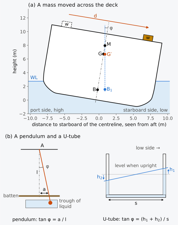
Figure 10.1 The principle of the inclining experiment. (a) A mass moved across the deck, with the heel drawn five times as large. (b) A pendulum and a U-tube, drawn in the ship’s frame with the angle exaggerated.
10.2 Preparing the test
10.2.1 The condition of the ship
Before the test, the ship is brought as close as possible to a condition that is fully known. The IS Code asks that the ship be as complete as possible, and if the mass or the position of an item still to be fitted cannot be known with confidence, the test is better done after it has been fitted4. Temporary material, tools, staging and debris are reduced to a minimum, persons not needed for the test leave the ship, and water, snow and ice are cleared from the decks, since water trapped on deck shifts like the liquid in a tank4. Movable and suspended items, such as boats and booms, are secured and their positions recorded2,4; a mass left free to swing would act at its point of suspension (Sec. 5.2.1) and make GM appear smaller.
Liquids are the main concern, because any liquid that shifts when the ship heels adds to the heel and makes GM appear smaller. Tanks should preferably be empty and clean, or pressed full, completely full with no air pockets; a tank 98 % full is not pressed up4. An empty tank is inspected after pumping to check that it is dry, because a thin layer of liquid in a wide tank has the full free surface moment of the tank4; any entry requires the applicable enclosed-space entry precautions. Where a tank must stay slack, the Code normally allows only one pair of tanks or one centreline tank to be slack. Such a tank should be of regular shape, so that its free surface moment can be calculated. It should also be between 20 % and 80 % full for a deep tank or between 40 % and 60 % full for a double-bottom tank, for the liquid to shift at a constant rate over the angles of the test. Cross-connections between tanks should be closed, and equal levels in a pair of slack tanks can be a sign that a cross-connection is open4.
The ship should float freely, and the IS Code asks that it be moored by slack lines at the bow and the stern, clear of the quay, in sheltered water, with gangways, power cables and hoses to the shore removed or kept slack4,4. The depth of water is measured beforehand, with the tide and the trim allowed for, so that the ship cannot touch the bottom; where the depth is marginal, the test is done at high tide or the ship is moved to deeper water4. Wind and current that hold it steadily off the quay superimpose a constant heeling moment, which does not spoil the test. Gusts and varying currents change that moment, and more readings may be needed4. The ship should be nearly upright, with no more than half a degree of list with the weights in their first position. The hydrostatic data used should allow for its actual trim and, where practical, for the deflection of its keel, and they are checked beforehand for the largest heel expected, since the waterplane may change as the ship heels4.
10.2.2 The weights and the instruments
The IS Code recommends inclining weights that heel the ship at least 1° and at most 4° to each side. For a large ship the Administration may accept a smaller heel, provided that the pendulums still deflect as much as the Code asks (Sec. 10.1.2), or the U-tubes still show the difference in height it asks for4. Beyond 4° the righting lever may no longer equal GM sin φ, and for a ship whose sides flare appreciably at the waterline amidships the heel is kept towards the lower end of that range2. The weights should be compact, so that the heights of their centres of gravity can be determined accurately. Each is marked with a number and its mass, and the masses are certified on a calibrated scale shortly before the test4,4. They are placed as far outboard as possible on the upper deck, and the deck is checked for their load4. For small ships, drums filled with water and capped may be used4.
The weights are chosen with the GM that the weight estimate gives. For a chosen angle, Eq. (10.1) gives the inclining moment needed,
and the length of the pendulums follows from the deflection wanted at the largest heel.
Example 10.2. Planning the weights. The weight estimate puts the Series 60 ship, in the condition in which it will be inclined, at 2918 t with GM about 1.25 m. The inclining weights can be moved 12.0 m across the deck over hold 3. (a) Find the inclining moment and the mass of weights needed on each side for a heel of 2°. (b) Four weights of 5.00 t are available, two on each side. Find the largest heel if two of them are moved across together, and the shortest pendulum that gives a deflection of 15 cm at that heel.
The IS Code lists the plans and data that the person in charge of the test needs: the lines plan, the hydrostatic data, the general arrangement, the capacity plan and the tank sounding tables, the positions of the draught marks and, if available, the docking drawing with the keel profile4. Figure 10.2 shows the arrangement of the test of this chapter.
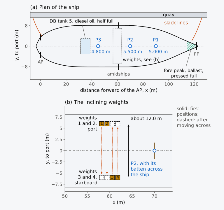
Figure 10.2 The arrangement of the illustrative inclining experiment of the Series 60 ship. (a) The ship, with breadths drawn twice as large as lengths. (b) The inclining weights, at true scale.
10.3 Displacement and the longitudinal position of G
10.3.1 Draughts and density
The displacement is found from the waterline at which the ship floats during the test. The Code recommends reading at least five freeboards, about equally spaced, on each side of the ship, or all the draught marks forward, amidships and aft on both sides, immediately before or after the test, with the weights and the persons in their places. A draught tube, open at the bottom, damps the waves at the marks4. Draught marks give extreme draughts, to the bottom of the keel, which are reduced to moulded draughts before they are used4. If the midship draught differs from the mean of the end draughts, the hull is hogged or sagged and its keel is bent; Sec. 3.6.1 showed how the displacement is then found. The density of the water is measured by a hydrometer on samples taken at depth, forward, amidships and aft on a large ship4.
10.3.2 Displacement, KM and the position of G
If the trim is small, the hydrostatic table of the ship on even keel can be entered at the draught at the centre of flotation F2. The table gives the displacement in sea water of 1.025 t/m³, which is converted to the density of the dock water. The longitudinal position of G follows from the trim by Eq. (6.12), and KM is read at that draught with no correction for the density, since at a given draught it depends only on the form of the hull.
The waterplane of a ship trimmed by a few tenths of a metre at a light draught is not the waterplane of the even-keel table, and KM can differ noticeably. A hydrostatics program computes the displacement, the centre of buoyancy and KM directly for the measured waterline from the hull model, and the IS Code allows the calculations of the test to be made by a program4. With the ship trimmed, G lies on the vertical through B, which is perpendicular to the waterline, not to the keel. If is the trim, positive by the stern, G then lies forward of B by , a small correction.
Example 10.3. Displacement and the position of G from the draughts. The Series 60 ship, 121.92 m between perpendiculars, is inclined in dock water of 1.020 t/m³. Its draughts at the perpendiculars and amidships, read at the marks and reduced to moulded draughts, are, port and starboard: aft 3.109 m and 3.106 m; amidships 2.753 m and 2.750 m; forward 2.394 m and 2.396 m. The hydrostatic table of the ship for even keel in sea water gives, at 2.75 m, = 2923.8 t, = 60.08 m, = 60.11 m, KM = 8.007 m and MCT 1 cm = 61.88 t·m/cm, and at 2.80 m, 2985.5 t, 60.08 m, 60.09 m, 7.932 m and 62.13 t·m/cm. Find (a) the trim and whether the hull is bent, (b) the draught at F, (c) the displacement mass in the dock water, (d) the longitudinal position of G and (e) KM, by the table.
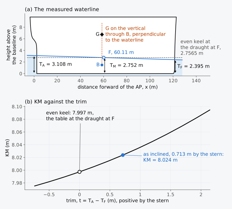
Figure 10.3 The Series 60 ship as inclined. (a) The measured waterline, with heights drawn five times as large as lengths. (b) KM at its displacement against the trim, computed on the hull.
10.3.3 A bent keel
In Example 10.3 the midship draught agreed with the mean of the end draughts. A discrepancy can indicate a bent keel, after allowing for measurement uncertainty and the draught marks’ reference positions. For an established hog or sag, Eq. (3.20) corrects the displacement; KM, too, must then be that of the bent hull. A hydrostatics program can compute both when it is given the waterline through the three measured draughts, for example as a wave twice as long as the waterline and twice as high as the deflection, with its trough amidships for a hog and its crest amidships for a sag5. Measured from the straight line joining the keel at the perpendiculars, KM of the Series 60 ship as inclined is 0.025 m higher with a hog of 0.030 m than for the straight hull at the displacement and trim as inclined, because the full midbody, and B with it, is lifted, while BM is unchanged within a millimetre (Fig. 10.4(a)). KM − GM then gives the height of G in the bent hull.
When the hull straightens, each mass moves vertically by the deflection at its station, and KG changes by the mean deflection weighted by mass. For a parabolic deflection this is 67 % of the deflection amidships for mass spread evenly along the length. Moore gives values up to 87 % for the tapered mass distributions he considers. Within those assumptions, the smaller fraction is conservative for a hog, which lowers G, and the larger for a sag, which raises it2. These fractions are approximations tied to the mass distribution, not universal bounds. The corrections to KM and to KG belong together, because the hog raises B by about the mean deflection weighted by volume, 85 % of the deflection amidships here, and G by the mean weighted by mass (Fig. 10.4(b)). For mass spread evenly, a hog ignored in both KM and KG leaves the lightship KG only 0.006 m too low, while correcting KM but not KG leaves it 0.020 m too high (Table 10.2).
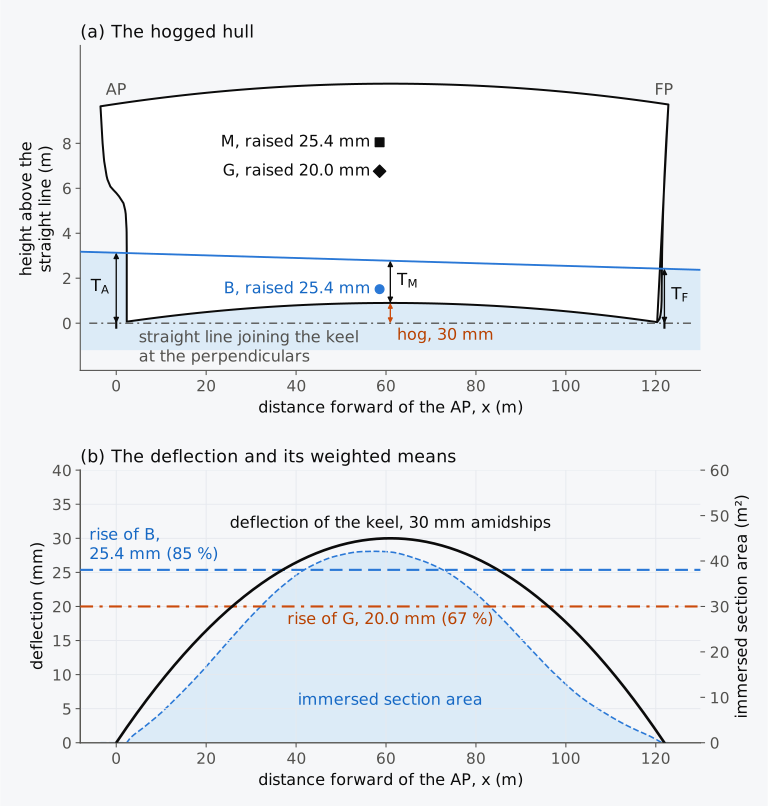
Figure 10.4 The Series 60 ship as inclined, hogged by 0.030 m. (a) Heights drawn five times as large as lengths, the hog a further 30 times. (b) The deflection of the keel and its weighted means.
10.4 The weight movements and the plot of tangents
10.4.1 The movements
The standard test of the IS Code moves the weights eight times. Each weight is moved across the ship, so that the trim does not change, and after each movement the distance moved is measured centre to centre and the inclining moment calculated4,4. The heel is read at every station at once when the pendulums have come to rest; if a wire still swings slightly, the centre of its swing is marked4. Moving the weights to give at least two angles on each side, the intermediate angles about half the largest, makes a wrong reading easier to identify2. One person at a central station directs the whole test, with two-way communication to the weight handlers and to every pendulum station4. Those who move the weights by hand stand on the centreline while the pendulums are read, so that their own mass does not heel the ship6.
In the test of this chapter, weights 1 and 2 start on the port side and weights 3 and 4 on the starboard side (Fig. 10.2). Weights 1 and 2 are moved to starboard in turn and back to port; then weights 3 and 4 are moved to port and back. Movements 4 and 8 return the ship to its first position and check the zero. A zero that does not return shows that something besides the weights has changed: a loose item has shifted, or liquid has found its way from one tank into another, perhaps past a valve that does not seal3, or a steady wind has come up4. The cause is found, and movements that did not give acceptable points are repeated or explained4. The readings are listed in Table 10.1, and the movements are shown in Animation 10.1.
Table 10.1 The readings of the illustrative inclining experiment of the Series 60 ship. Moments and heel positive to starboard. Deflections in millimetres; the mean tangent is the mean of over the three pendulums.
| Movement | Weights moved | from the first position (t·m) | P1, = 5.000 m | P2, = 5.500 m | P3, = 4.800 m | Mean tan φ |
|---|---|---|---|---|---|---|
| 0 | first position | 0 | 0 | 0 | 0 | 0 |
| 1 | 1 to starboard | 60.10 | 83 | 91 | 79 | 0.01653 |
| 2 | 1, 2 to starboard | 120.00 | 166 | 182 | 158 | 0.03307 |
| 3 | 1 back to port | 59.90 | 82 | 91 | 80 | 0.01654 |
| 4 | 2 back to port | 0 | 0 | −1 | 1 | 0.00001 |
| 5 | 3 to port | −60.20 | −82 | −91 | −80 | −0.01654 |
| 6 | 3, 4 to port | −120.00 | −165 | −181 | −159 | −0.03301 |
| 7 | 3 back to starboard | −59.80 | −82 | −91 | −79 | −0.01647 |
| 8 | 4 back to starboard | 0 | 0 | −1 | 0 | −0.00006 |
Historical note: the inclining experiment in 1899
10.4.2 The plot of tangents
As the test proceeds, the tangent of each heel is plotted against the inclining moment, as the IS Code recommends4. By Eq. (10.1) the points should lie on a straight line whose slope is (Fig. 10.5). The line need not pass through the origin, because no single point, the first zero included, is more significant than the others, and a linear regression is often used to fit it2,4. For points , with the inclining moment and the tangent, the least-squares slope is
and
A line may instead be fitted through the origin5; fitted to the tangents against the moments, it has the slope . When the moments to port and to starboard balance, , and the two fits have equal slopes.
A plot that is not straight calls for investigation: other moments, changing hydrostatics or measurement errors may be involved. The IS Code gives examples of disturbed patterns and their remedies4. A ship touching the bottom or held by a tight mooring line heels less than it should beyond some angle, so the outer points fall short of the line. A steady wind that rises after the first zero moves every later point by an equal amount, which leaves the slope unchanged when the moments to port and to starboard balance; a gusty wind scatters the points. In the Code’s example of excessive free liquid, the plot curves away from the line at the largest moments on both sides, the ship heeling further than the line predicts, and the remedy is to check all tanks and voids, pump out as necessary, and repeat all the weight movements and the draught readings4.
Free liquid can also leave no trace on the plot. If its free surface moment stays constant over the angles of the test, the plot stays straight and only becomes steeper, and GM comes out too small. Tank soundings and inspection are therefore essential; the plot alone cannot exclude unrecorded liquid. The disturbed plots of Fig. 10.6, computed for the Series 60 ship, include free liquid with a constant free surface moment. A plot of each pendulum also reveals a pendulum whose length was measured wrongly, because its tangents are consistently larger or smaller than the others2. A wrongly recorded mass does not show on the plot at all when a single weight is used2, and neither does an error common to all the weights, such as that of a faulty scale, because it changes every moment in proportion.
A condensed inclining report may also list the GM of each movement2, . These values show how well the movements agree, but their mean is not the result. Each divides one moment by one tangent, so a reading error or a shift of the zero weighs most on the movements with the smallest moments. A movement with almost no moment gives no usable value at all, and a line drawn with the mean of the values fits the readings poorly5. When the moments balance, the slope of Eq. (10.5) is the mean of the ratios weighted by , so the smallest moments count least, and a constant shift of the tangents passes into the intercept. In the steady wind of Fig. 10.6(c), the six values of GM run from 1.07 m to 1.50 m and average 1.27 m, while the line gives 1.247 m.
Example 10.4. The plot of tangents. Find GM of the Series 60 ship as inclined from the mean tangents of Table 10.1, by Eqs. (10.5) and (10.6), with the displacement mass of the measured waterline, 2917.8 t.
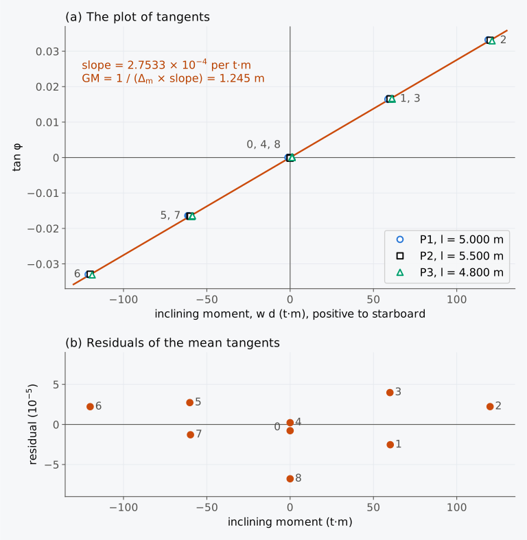
Figure 10.5 The plot of tangents of Table 10.1. (a) The tangents of the three pendulums, offset slightly along the moment axis, and the fitted line. (b) The residuals of the mean tangents.
Animation 10.1 The inclining experiment of the Series 60 ship, movement by movement. Above, its midship section with the weights on deck, and below it the batten of pendulum P2 with the position of its wire; the weights move across one at a time, and the ship settles at each new angle. At the bottom, the plot of tangents, with a point added for each movement and the fitted line drawn at the end. No sound; 22 s.
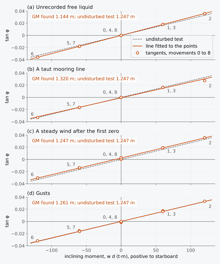
Figure 10.6 Plots of tangents disturbed by other moments, computed for the Series 60 ship as inclined. (a) Unrecorded free liquid, free surface moment 300 t·m. (b) A mooring line taut beyond 1.2° to starboard. (c) A steady wind from port after the first zero, a moment of mass of 10 t·m. (d) Gusts, moments of mass up to 8 t·m.
10.5 From the ship as inclined to the lightship
10.5.1 Free surfaces during the test
The GM measured is the GM of the ship as it floats, with every free surface in it. If slack tanks were left, the KG of Eq. (10.2) is the virtual height of G, and the free surface correction of Chapter 5 is subtracted to find where G actually is:
where is the sum of the free surface moments of the slack tanks2. For a rectangular tank with vertical sides, of length and breadth , the IS Code gives the free surface moment as , which does not contain the depth of the liquid, and notes that the correction does not depend on the height or position of the tank in the ship or on the direction of heel4. A liquid that reaches the top or the bottom of its tank within the angles of the test has a free surface that changes in size, and its moment is not constant. Instead of a free surface correction, its shift can be added to the inclining moment as a mass moved a known distance2.
10.5.2 The lightweight survey
The ship as inclined is not the lightship, since some items of the lightship are not yet on board and many things on board do not belong to it: the inclining weights and pendulums, staging and tools, the persons on board, and the liquids in the tanks. The lightweight survey is the audit of every item to be deducted, added or relocated to bring the ship as inclined to the lightship condition, with the mass and the position of each4. It is made by at least two persons walking through every space, and every tank with liquid in it is sounded4. Where a mass must be estimated, the Code asks for estimates on the safe side: high for items to be added high in the ship and low for items to be added low, and the reverse for items to be removed4.
If the ship as inclined has the displacement mass with its centre of gravity at , the items deducted have masses at , the items added at , and the items relocated move from to , the lightship has
the moments of Eq. (3.9) taken item by item2,5. The inventory must be thorough and accurate, because the position of G found by the experiment is the basis of the ship’s stability for the rest of its life2.
Example 10.5. The lightship of the Series 60 ship. As inclined, the Series 60 ship displaces 2917.8 t, its centre of buoyancy lies 58.573 m forward of the AP and 1.488 m above the baseline, KM is 8.024 m and its trim is 0.713 m by the stern on a length of 121.92 m. Example 10.4 found GM = 1.245 m. Diesel oil half fills double-bottom tank 5, 7.4 m long and 6.05 m wide, with a free surface moment of 116.1 t·m. The lightweight survey found the items of the table below. Find the lightship mass and the position of its centre of gravity.
Item (t) (m) (m) To deduct Inclining weights, four of 5.00 t 20.00 60.00 10.15 Pendulums, staging, tools and debris 7.40 48.00 8.60 Persons on board, 14 of 75 kg 1.05 55.00 11.00 Diesel oil, DB tank 5, half full 19.00 35.03 0.25 Fore peak ballast, pressed full 60.33 116.59 4.49 To add Deckhouse outfit and furniture 12.60 37.00 12.40 Hatch covers, hold 1 14.20 105.50 10.60 Lifeboat and davits 7.80 33.00 15.20 Spare propeller 5.40 30.00 1.80 To relocate Anchors, from the deck 8.40 112.00 10.25 Anchors, to the hawse pipes 8.40 116.50 8.40
The items of the survey are drawn at their positions in Fig. 10.7(a), and the path of G from the ship as inclined to the lightship in Fig. 10.7(b). The deductions move G 1.07 m aft and 0.061 m up. The shift aft comes from the fore peak ballast, the largest item and the furthest forward, and the rise from that ballast and the diesel oil, both low in the ship. The items added, most of them high in the ship, and the anchors moved take G 0.04 m forward and 0.052 m up.
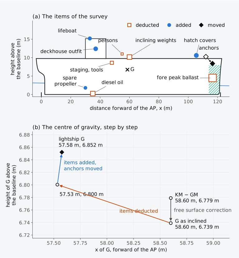
Figure 10.7 The lightweight survey of Example 10.5. (a) The items at their positions, heights drawn 2.5 times as large as lengths; a larger marker is a larger mass. (b) The path of G to the lightship.
The inclining report must allow the analysis to be checked again if any value is questioned later, and its record begins on board: under the IS Code, the person conducting the test and the Administration’s representative initial each data sheet before leaving the ship4. The report therefore keeps the readings themselves, from which the moments and tangents are worked out: the mass of every weight and each distance it travelled, and the length of each pendulum with all its deflections. Tank soundings are entered as taken, and the liquid masses are derived from them with the sounding tables, corrected for trim where needed. From these data the displacement and centre of gravity as inclined are worked out, and then the lightship2. The report forms part of the ship’s stability booklet4.
10.5.3 Inclining test calculator (Calculator 10.1)
Calculator 10.1 analyses an inclining experiment. You enter the ship as inclined (its displacement, KM, the free surface moments, and , KB and the trim for the position of G), the lengths of the pendulums, the inclining moments and the deflections, and the items of the lightweight survey. It plots the tangents, fits the line by Eq. (10.5), and finds GM, KG and the lightship by Eqs. (10.6) to (10.8). The working follows Examples 10.4 and 10.5 step by step. The calculator also flags deflections below 15 cm, zero checks that do not return, points far from the line and heels outside the recommended 1° to 4°, noting that the Administration may accept a smaller heel for a large ship.
10.6 The accuracy of the result
10.6.1 Sources of error
An error in the length of a pendulum, in its deflection, in the mass of the weights or in the distance moved makes a proportional error in GM2. Errors in the inventory pass unchanged into the lightship mass2. An error in the draughts changes the displacement mass by the TPC for each centimetre. It also changes KM, which can fall quickly with increasing draught in a light condition; the actual sensitivity must be read from the ship’s hydrostatics2. With , Eq. (10.1) gives GM as , and small errors in its five quantities change it by
When the input quantities have independent standard uncertainties , the standard uncertainty of GM is
and the uncertainty of KG combines that of GM with that of KM, together with their correlation where there is one. Known significant biases must be corrected first. Taking KM for the wrong waterline, or leaving out a free surface, is not remedied by averaging more readings. The uncertainties that remain, those of the corrections among them, belong in the uncertainty budget. Equation (10.9) applies when the inputs are independent, and correlated inputs need covariance terms8. For fixed relative uncertainties of the inputs, the part of the uncertainty in KG that comes from GM becomes smaller as GM decreases. The uncertainties in KM and in the free surface corrections need not do so. A reading error of 1 mm on a deflection of 150 mm is 0.7 % of GM for a single reading (Fig. 10.8). The fit through many independent readings reduces this random part, but not a calibration bias that all the readings share. A finer instrument does not justify a smaller heel. The moments of wind, moorings and persons on board do not shrink with the error of the instrument, and the smaller the inclining moment, the larger their share. The IS Code asks that other measuring devices not be used to reduce the minimum angle of heel4.
Table 10.2 lists errors of plausible sizes in the test of this chapter and their effect on the lightship KG of the Series 60 ship. In these illustrative cases the random reading errors change the lightship KG by only a few millimetres; the larger effects come from KM taken for the wrong waterline, and liquid that nobody recorded. Fuel oil of 0.98 t/m³ left 0.20 m deep in the two tanks of double bottom 3, each 6.9 m wide, has the free surface moment of the whole tanks. It makes the GM found 0.427 m too small, and with its 62.8 t counted in the lightship, low down, which offsets part of that error, the lightship KG found is 0.285 m too high.
The limits that apply when a ship is altered in service, stated in Sec. 10.8, are not limits on the accuracy of an inclining, but they give a scale for its errors. An alteration that changes the height of the lightship G by more than 0.5 % calls for amended stability information, and an alteration that changes it by more than 1 % for a new inclining. For the Series 60 lightship, whose G lies 6.852 m above the baseline, these are 0.034 m and 0.069 m. The error in the lightship KG from KM taken from the even-keel table, 0.027 m, is about four-fifths of the first, and the error from the unrecorded oil is about four times the second.
An error in the lightship KG reaches every loading condition, reduced in the ratio of the lightship mass to the displacement mass. In the departure condition of the Series 60 ship, 7707 t with GM 0.659 m, this ratio is 2850/7707 = 0.370. KM read from the even-keel table puts the lightship KG 0.027 m too low and would make the GM of that condition appear 0.010 m larger than it is. The unrecorded oil, which also changes the lightship mass, would make that GM appear roughly 0.1 m smaller, about a sixth of its value.
Table 10.2 Errors in the inclining experiment of the Series 60 ship and their effect on the lightship KG found. Illustrative sizes. A positive effect puts the lightship G too high, and the stability assessed from it is understated.
| Source | Error | Effect on GM (m) | Effect on lightship KG (m) |
|---|---|---|---|
| Scatter of the readings, about the fitted line | 2 standard errors of the slope | ±0.002 | ∓0.002 |
| Length of the pendulums | ±5 mm in 5 m | ±0.001 | ∓0.001 |
| Mass of the inclining weights | ±0.25 % | ±0.003 | ∓0.003 |
| Distance moved | ±2 cm in 12 m | ±0.002 | ∓0.002 |
| Density of the dock water | ±0.001 t/m³ | ∓0.001 | ±0.001 |
| Draughts read 5 mm too deep | +6.1 t displacement mass; KM −0.008 m | −0.003 | −0.005 |
| KM from the even-keel table at 0.71 m trim | KM −0.027 m | 0 | −0.027 |
| KG not corrected for a hog, KM for the bent hull | hog of 0.030 m; mass spread evenly | 0 | +0.020 |
| Hog ignored in both KM and KG | hog of 0.030 m; mass spread evenly | 0 | −0.006 |
| Unrecorded fuel oil, 0.20 m in both tanks of DB 3 | 62.8 t; free surface moment 1244.8 t·m | −0.427 | +0.285 |
| A 2.0 t item added in the survey, placed 3.0 m too low | 0 | −0.002 |
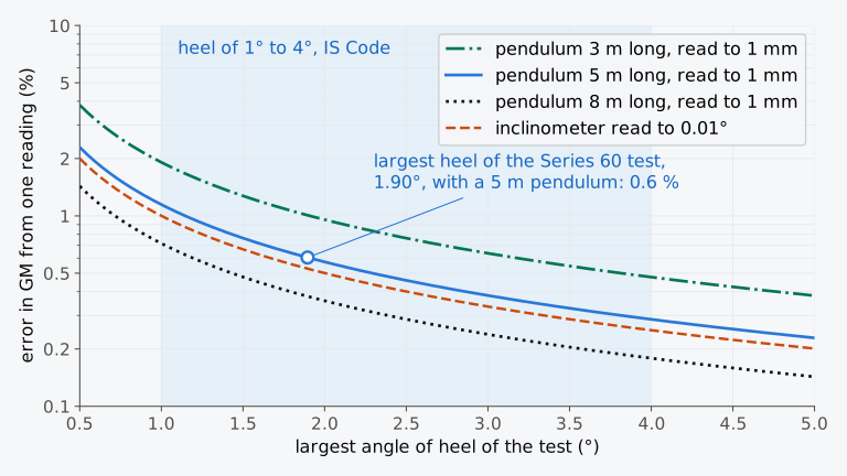
Figure 10.8 The error in GM from a single reading against the largest heel of the test, for pendulums of three lengths read to 1 mm and for an inclinometer read to 0.01°.
10.6.2 Exploring the experiment (Explorer 10.1)
In Explorer 10.1 you run the inclining experiment of the Series 60 ship yourself. You choose the mass of the weights, the length of the pendulum and how finely it is read, and you can add the disturbances of Fig. 10.6: unrecorded free liquid, a mooring line that becomes taut, a steady wind from port after the first zero, and gusts. The explorer plots the tangents, fits the line and compares the GM and KG found with the true values. Try the smallest weights that still meet the Code’s usual 1°, and then a slack tank that nobody recorded.
10.7 Other ways to find the centre of gravity
The inclining experiment is the usual way to find the centre of gravity, but there are others.
Sister ships. Under the IS Code, the Administration may allow a ship not to be inclined if the inclining of a sister ship gives reliable stability information for the ship, and the lightship mass of the ship and its longitudinal centre differ from the sister’s by less than set limits4. The stability booklet then contains the inclining report of the sister ship with the lightship measurement report of the ship itself4. The International Convention for the Safety of Life at Sea, 1974, SOLAS, allows the inclining of an individual cargo ship to be dispensed with in this way. It requires a lightweight survey on completion, and an inclining if the lightship mass differs from the sister’s by more than 1 % for a ship 160 m or more in length and 2 % for a ship 50 m or less, interpolated linearly between, or its longitudinal centre by more than 0.5 % of the length9. The explanatory notes to the subdivision and damage stability regulations of SOLAS, adopted by the International Maritime Organization in Resolution MSC.429(98)/Rev.2, define a sister ship as a cargo ship built by the same yard from the same plans10. The ship’s own lightweight survey then gives the lightship mass and its longitudinal and transverse centres. The height of G is taken as the higher of the inclined sister’s value and that value adjusted by calculation for the known differences between the two ships10.
Inclining in air. A small boat can be inclined hanging in air, which avoids the effects of water and draughts. The boat hangs in slings from a knife edge parallel to its baseline, and the knife edge rests on two scales, forward and aft; the sum of the readings is its mass, and their moments give the longitudinal position of G. Inclining weights and a pendulum are used as in water, but the boat now turns about the knife edge, which takes the place of the metacentre2. If is the height of the knife edge above the keel and the mass hung, the height of G is
Ballast water. Where solid weights are impractical, the IS Code allows water to be moved between wall-sided tanks directly opposite each other, if the Administration accepts it for that test. The tanks are sounded before and after each shift, and the moment of the water is calculated for each angle of heel4.
The period of roll. A small ship can be made to roll in calm water by persons moving across the deck in time with its roll, which is called sallying, and the period of a number of rolls is timed2. With GM from the inclining experiment, the period gives the coefficient of Eq. (4.11) for this ship. Later, the period measured again gives an approximate GM, as long as the distribution of mass has not changed much. A value of out of line with those of similar ships points to an error in the experiment or a difference in construction2.
Pontoons. The IS Code does not require a pontoon to be inclined if its lightship KG is taken conservatively, at the main deck unless a lower value is documented4.
10.8 The Ethan Allen and the lightship in service
The investigators of the National Transportation Safety Board (NTSB) inclined the de Champlain on 5 October 2005, following the guide ASTM F1321-91 and moving water barrels of 477 lb (216 kg) across its deck1. They also weighed both boats, the de Champlain at 14,870 lb (6.745 t) and the Ethan Allen at 15,400 lb (6.985 t). With the experiment and these weighings, naval architects contracted by the board reconstructed the lightship of the Ethan Allen in its successive forms1.
As delivered in 1964, without a canopy, the boat’s lightship had weighed 12,759 lb (5.787 t), with its centre of gravity 4.5 ft (1.37 m) above the baseline. In 2005, with the wooden canopy, it weighed 14,689 lb (6.663 t), with its centre of gravity 5.3 ft (1.62 m) above the baseline1. In 41 years the boat had gained 15 % in mass, about the mass of 14 passengers at the 140 lb (63.5 kg) per person of the Coast Guard criteria1, and G had risen 0.24 m. Much of the change came with the canopies. With the first canopy, of canvas on a metal frame, the board put the lightship at 14,590 lb (6.618 t), with its centre of gravity 5.4 ft (1.65 m) above the baseline, if the frame was of steel, and at 13,542 lb (6.143 t) and 4.9 ft (1.49 m) if it was of aluminium1.
With the lightship found, the board’s calculations limited the boat, in its final form and in the fresh water of the lake, to 49 persons under the criterion for heel when passengers crowd to one side, 21 under the criterion for wind heel and 14 under the criterion for vessels of unusual proportion and form1. The board found that the Ethan Allen capsized because its stability was insufficient to resist a passing wave, a sharp turn and the shift of the passengers to port that followed, and that the boat carried 48 persons where it should have carried 14. The failure to reassess the stability after the modifications contributed to the accident1.
The inclining experiment fixes the lightship on the day of the test, and the stability information built on it holds only while the lightship stays as it was. In service a lightship grows with layers of paint and rust scale, with marine growth on the shell, and with refitted accommodation and equipment, and it shrinks as steel corrodes and moving parts wear. Other weights collect on board over the years: sediment in oil tanks and mud in ballast tanks, cargo residues, dunnage and lashing material, and additional spare parts11. They do not belong to the lightship, and a lightweight survey lists and deducts them, as in Sec. 10.5.2, unless they are to stay on board permanently. Each change has its own centre of gravity, so the height of G changes with the mass.
The Ethan Allen carried passengers on a lake within one state, under that state’s certificate. SOLAS applies only to ships on international voyages, unless it provides otherwise9, and it did not govern the boat. For the ships to which it applies, SOLAS limits how far the lightship may change before the ship is inclined again. Every passenger ship receives a lightweight survey at intervals of no more than five years, and is inclined again if its lightship mass is found to differ from the approved value by more than 2 %, or the longitudinal centre of that mass by more than 1 % of the length9. Such a survey finds the mass and its longitudinal centre, but not the height of G, which only an inclining measures. When the survey finds changes within these limits, the explanatory notes to the subdivision and damage stability regulations of SOLAS, in Resolution MSC.429(98)/Rev.2, ask that all later stability information use the mass and the longitudinal and transverse centres found by the survey with the height of G from the most recent inclining10.
When any ship is altered so as to affect its stability information materially, the information must be amended, and the ship must be inclined again where necessary, and in any case when the expected changes exceed either limit of the survey9. The explanatory notes set out how an alteration is judged. The lightship is recalculated from the weights and centres of gravity of the alteration and compared with the approved values. The ship should be inclined again if the recalculated mass or its longitudinal centre exceeds either limit of the survey, or if the height of G differs by more than 1 %. Within these limits, the stability information should be amended if the mass differs by more than 1 %, its longitudinal centre by more than 0.5 % of the length or the height of G by more than 0.5 %, and otherwise it need not be amended. The transverse centre is not subject to a limit, and successive alterations are judged by their total since the most recent inclining10. The unified interpretation of SOLAS chapter II-1, MSC.1/Circ.1362/Rev.2 of 14 July 2023, applies the total in this way whatever the ship’s keel-laying date12.
The checks of the inclining experiment are listed in order in Table 10.3, from the condition of the ship to the lightship.
Table 10.3 Checklist of the inclining experiment, from the condition of the ship to the lightship.
| Check, and where it is treated |
|---|
| Set-up and conditions |
| Ship as complete as possible; temporary material reduced to a minimum; persons not needed and water on deck removed; movable items secured (Sec. 10.2.1) |
| Tanks empty and dry or pressed full; normally at most one pair, or one centreline tank, slack, of regular shape, between 20 % and 80 % full (deep tank) or between 40 % and 60 % full (double bottom); cross-connections closed (Sec. 10.2.1) |
| Slack moorings and shore connections; depth checked with the tide and the trim; no more than half a degree of list; hydrostatic data for the actual trim (Sec. 10.2.1) |
| Certified weights for a heel of 1° to 4° to each side, or less for a large ship if the Administration accepts it (Sec. 10.2.2); at least two pendulums, three recommended, each deflecting at least 15 cm (Sec. 10.1.2) |
| Freeboards or draught marks read on both sides, reduced to moulded draughts; density of the dock water measured (Sec. 10.3.1) |
| Displacement, KM and for the measured waterline, with its trim (Sec. 10.3.2) and any hog or sag (Sec. 10.3.3) |
| Acceptance of the readings |
| Eight movements, each distance measured centre to centre; heel read when the pendulums have come to rest (Sec. 10.4.1) |
| Zero returned after movements 4 and 8; otherwise the cause found and the movements repeated or explained (Sec. 10.4.1) |
| Tangents of each pendulum plotted as the test proceeds; departures from a straight line investigated for other moments, changing hydrostatics or measurement errors (Sec. 10.4.2) |
| The fit |
| Least-squares line through all the points, Eqs. (10.5) and (10.6), not the mean of the GM of each movement |
| The uncertainty |
| Known significant biases corrected; remaining input and correction uncertainties combined, including correlations where present; Eq. (10.9) covers independent inputs (Table 10.2) |
| The correction to the lightship |
| Free surface correction of the slack tanks subtracted from KM − GM, the virtual height of G found with the measured GM, to give the actual KG, Eq. (10.7) |
| Lightweight survey of every space, every tank with liquid sounded; items deducted, added and relocated, estimates on the safe side, Eq. (10.8) |
| Report that keeps the readings themselves (Sec. 10.5.2) |
10.9 The inclining experiment in industry today
This section describes practice in 2026.
Rules and standards. Within its scope and subject to its stated exemptions, SOLAS requires passenger ships, whatever their size, and cargo ships 24 m or more in length to be inclined on completion9. The IS Code sets out how the test is prepared and conducted, with detailed guidance in an annex that this chapter follows4. ASTM F1321, the standard guide on which the investigators of the Ethan Allen based their test, is now in its edition F1321-21. It covers the lightweight survey and the inclining experiment of vessels of conventional hull form, made to determine the lightship displacement and its longitudinal and vertical centres. Its scope notes that its limits on trim and heel apply where hydrostatic characteristics calculated beforehand are used, and not where the hydrostatics are calculated for each weight movement, as a computer program can do13.
Instruments. The IS Code still treats the pendulum as the reference. It allows U-tubes and inclinometers in place of some pendulums, at the discretion of the Administration, and recommends that they be used only together with at least one pendulum4. A mean absolute difference of 0.03°, with a standard deviation of 0.02°, separated the readings of a liquid capacitive inclinometer on board a ship from those of a camera that followed the horizon at sea14. A pendulum 5 m long read to 1 mm resolves 0.011°. In a project of the US National Shipbuilding Research Program led by NASSCO with Austal, a digital level, high-precision inclinometers with data acquisition and a phone application are being compared during inclinings, to validate the statement of ASTM F1321-21 that digital measuring devices can be used in place of a pendulum. The October 2026 update reports preliminary NASSCO trials and ongoing work with ABS on acceptance of the methods. It schedules full implementation on Austal T-ATS 11 for November 2026 and presentation of results for March 2027; it does not yet report comparative accuracy results15.
Uncertainty. Woodward and co-authors set out a procedure for a confidence interval on the KG found by an inclining experiment, and for carrying it to any loading condition16. Taylan combined the errors of several sources into a margin of error for GM and KG at a stated confidence and compared it with the reports of actual experiments17. Applying an uncertainty analysis to two historic experiments, Hansch found the displacement as inclined to be the largest source of uncertainty in the lightship KG, and recommended correcting the displacement for the deflection of the hull by wedges rather than by the mean of means, Eq. (3.21), with its factor of three quarters18.
Data. The sources consulted for this section describe no common format for exchanging the data of an inclining experiment between programs; where the Administration requires it, the Code asks that the inclining data be forwarded with the results in a report format that it accepts4.
10.10 From the lightship to the stability information
The lightship that the experiment fixes, for the Series 60 ship 2850 t with its centre of gravity 57.58 m forward of the AP and 6.85 m above the baseline, is the starting point of every loading condition. In the weight tables of Chapter 3 the deadweight was added to it, and in Chapter 5 the free surfaces were allowed for. In Chapters 8 and 9 each condition then became a curve of righting levers and was tested against heeling moments. On board, these results are needed in a form that can be used for the conditions actually loaded, together with the limits that each condition must meet. In Chapter 11 we will see the intact stability criteria of the IS Code and the stability information that is approved for each ship and carried on board.
Summary
- The inclining experiment finds GM from the small heel caused by moving a known mass across the ship, Eq. (10.1), and KG from KM of the waterline as inclined, Eq. (10.2). The angle is measured by pendulums, Eq. (10.3), U-tubes or inclinometers.
- The ship is prepared so that every mass on board is known and nothing but the inclining moment heels it: tanks empty or pressed full, normally at most one pair of slack tanks or one slack centreline tank, slack mooring lines, a heel of normally 1° to 4°, pendulum deflections of at least 15 cm, Eq. (10.4).
- The draughts give the displacement and the longitudinal position of G. The hydrostatic data must be those of the actual trim; for the Series 60 ship trimmed 0.71 m by the stern, the even-keel table gives KM 0.027 m too low. For a bent keel, KM is that of the bent hull, and KG is corrected by the mass-weighted mean deflection. The 67 % to 87 % approximations assume a parabolic bend and the mass distributions described in Sec. 10.3.3.
- The tangents of eight movements are plotted against the moments; the slope of the line, Eq. (10.5), gives GM, Eq. (10.6), and the mean of the GM of each movement is not used. A zero that does not return or a plot that is not straight calls for investigation of restraints, wind, liquid, hydrostatics and measurement errors. A constant free surface can leave the plot straight.
- The GM measured includes the free surfaces of slack tanks, Eq. (10.7). The lightweight survey of items to deduct, to add and to relocate turns the ship as inclined into the lightship, Eq. (10.8). The report keeps the basic readings, so that the results can be checked again.
- Equation (10.9) combines independent input uncertainties. Known biases must be corrected and correlations included where present. In the illustrative cases of Table 10.2, KM for the wrong waterline and unrecorded liquid have larger effects than random reading errors. An error in the lightship KG reaches each loading condition in the ratio of the lightship mass to the displacement mass.
- Small boats can be inclined in air, Eq. (10.10). The period of roll, calibrated by the experiment, gives an approximate check of GM later, as long as the distribution of mass has not changed much.
- The Ethan Allen had gained 15 % in lightship mass and 0.24 m in the height of G since delivery, much of this with its canopies, and its stability had not been assessed again; with the lightship found after the accident, the boat should have carried 14 persons, not 48. For ships under SOLAS, limits on the change of the lightship mass, its longitudinal centre and the height of G decide when the stability information of an altered ship is amended and when the ship is inclined again.
Notes on the data
The Ethan Allen. The accident, the boat, its modifications, the tests after the accident and their results are from the report of the National Transportation Safety Board1. None of its data is used in the calculations of this chapter.
The illustrative inclining experiment. The lightship of the Series 60 ship is that of Chapter 3: 2850 t, with its centre of gravity 57.58 m forward of the AP, on the centreline and 6.85 m above the baseline. The condition in which the ship is inclined is built from it with an illustrative inventory: the items of Example 10.5, the diesel oil tank of Table 5.1 half full and the fore peak tank, the hull forward of the collision bulkhead at 114 m and below 8 m, pressed full of sea water ballast of 1.025 t/m³. The ship floats in dock water of 1.020 t/m³. The floating position, the draughts and KM for the measured waterline are computed on the whole hull of Chapter 8 with the trim free, the free surface of the diesel oil being taken as a virtual rise of G. For each weight movement the angle of heel is found on the hull, with G moved across by the inclining moment. The pendulum readings are the tangents of these angles times the pendulum lengths, with a small disturbance common to the three pendulums and reading errors of about a millimetre, both drawn from a fixed random sequence, and they are rounded to the millimetre. The draught readings carry differences of a few millimetres between the two sides. The masses, positions and distances of the inventory and of the weights are illustrative.
The hydrostatic table. The table of Example 10.3 is that of Chapter 7, computed on the Series 60 hull on even keel every 0.05 m, in sea water of 1.025 t/m³.
The bent hull. The rise of KM with a hog in Sec. 10.3.3 is computed on the Series 60 surface for the ship as inclined, 2917.8 t in the dock water with a trim of 0.71 m. Each section is raised above the straight line joining the keel at the perpendiculars by a parabola, 0.030 m amidships and zero at the perpendiculars, and the waterline is moved to keep the displacement; KM is measured from that line.
Exercise 10.13. A steady heeling moment of 2.9 t·m, taken as a moment of mass, deflects each pendulum by 0.0008 times its length; this deflection, rounded again to the millimetre, is added to each reading of Table 10.1 from movement 4 on.
Explorer 10.1 and Calculator 10.1. The explorer uses the ship as inclined, 2917.8 t with a true GM of 1.2470 m and KM 8.024 m, and treats the angles as small: each tangent is the moment over , as in Eq. (10.1), with the moments of the disturbances added. A taut mooring line holds the ship with a stiffness of 3000 t·m per unit of tangent beyond the angle chosen. The gusts and the reading errors follow fixed sequences, so that a setting always gives an identical plot; with the weights of the test and no disturbance, the reading errors put KG about 0.002 m out. Figure 10.6 uses this model. The calculator rounds the mean tangents to five decimals, or more for tangents below 0.001, and the sums as in Example 10.4.
Exercises
Under each exercise, “Show answers” opens its short answers and “Show full solution” its worked solution. Unless stated otherwise, the masses are in tonnes and the ship has no free surfaces at the time of the test.
10.1 A ship of displacement mass 4200 t is inclined by moving a mass of 12.0 t across the deck through 10.50 m. A pendulum 6.000 m long deflects 142 mm. KM for its waterline is 7.100 m. Find (a) GM and (b) KG.
10.2 A ship of 1850 t is expected to have GM = 0.95 m at its inclining. Two weights of 3.0 t each are to be moved together across the deck through 9.00 m. Find (a) the angle of heel, (b) the deflection of a pendulum 4.000 m long and whether it meets the 15 cm of the IS Code, and (c) the shortest pendulum that does.
10.3 A model of the Series 60 ship at a scale of 1:40 is ballasted for tests in a towing tank of fresh water, 1000 kg/m³. It is to represent the ship with = 7519.0 m³ on an even keel, KM = 6.546 m and KG = 5.887 m. Four masses of 0.100 kg, part of its ballast, two on each side, are moved 0.300 m across the model, giving moments of 0, 0.030, 0.060, 0.030, 0, −0.030, −0.060, −0.030 and 0 kg·m, positive to starboard. An inclinometer on the model reads 0.05°, 1.04°, 2.05°, 1.06°, 0.05°, −0.94°, −1.95°, −0.96° and 0.06°. (a) Find the mass of the model and its KM. (b) Find GM by Eqs. (10.5) and (10.6), and explain why the 0.05° read before the first movement needs no correction. (c) Find KG of the model and the KG of the ship that it represents. (d) Find how far a ballast mass of 2.0 kg must be lowered to bring the model to the intended KG.
10.4 A ship of 5600 t is inclined with two pendulums and a U-tube whose legs are 14.0 m apart. When 10.0 t is moved 14.0 m to starboard, the reading rises 146 mm on the starboard leg and falls 146 mm on the port leg. Find the angle of heel and GM.
10.5 A ship of 3400 t is inclined with a slack fuel oil tank on board, rectangular with vertical sides, 9.0 m long and 7.2 m wide, with oil of density 0.95 t/m³. The plot of tangents gives GM = 0.884 m, and KM for its waterline is 7.512 m. Find (a) the free surface moment of the tank and (b) KG.
10.6 The Series 60 ship, 121.92 m between perpendiculars, is inclined in a river berth, in water of 1.010 t/m³, with draughts of 2.955 m aft and 2.585 m forward at the perpendiculars and 2.770 m amidships. Its even-keel table in sea water gives, at 2.75 m, = 2923.8 t, = 60.08 m, = 60.11 m and MCT 1 cm = 61.88 t·m/cm, and at 2.80 m, 2985.5 t, 60.08 m, 60.09 m and 62.13 t·m/cm. Find (a) the draught at F, (b) the displacement mass and (c) the longitudinal position of G.
10.7 At an inclining, a ship whose TPC is 12.3 t/cm reads draughts of 3.130 m aft, 2.720 m amidships and 2.370 m forward. (a) Is the ship hogged or sagged, and by how much? (b) Find the mean draught by the mean of means, Eq. (3.21). (c) By how much would the displacement mass be overstated if the mean of the end draughts were used? (d) Its displacement and KM are computed for the bent hull, and the analysis then puts G 6.800 m above the straight line joining the keel at the perpendiculars. If the mass is spread evenly along the length, find the height of G of the straight hull.
10.8 As inclined, a small cargo ship displaces 1240.0 t with KG = 4.86 m, after the free surface correction, and = 38.20 m forward of the AP. The survey finds, to deduct: inclining weights 16.0 t at = 40.0 m, = 7.10 m; fore peak ballast 22.0 t at 74.5 m, 3.40 m; persons and gear 2.4 t at 36.0 m, 7.50 m; and to add: liferafts and davit 3.2 t at 18.0 m, 9.80 m; galley equipment 1.6 t at 15.0 m, 7.90 m. Find the lightship mass, and .
10.9 A small vessel of 420.0 t is inclined with one inclinometer. The moments, in t·m, and the tangents are: 0 and 0; 2.40 and 0.0071; 4.80 and 0.0142; 2.40 and 0.0070; 0 and 0.0001; −2.40 and −0.0072; −4.80 and −0.0141; −2.40 and −0.0070; 0 and 0. (a) Find GM by Eqs. (10.5) and (10.6). (b) Explain why the line through the origin gives an equal slope. (c) Which recommendations of the IS Code for the instruments and the angles does this test not meet?
10.10 In the test of Examples 10.4 and 10.5 the ship displaced 2917.8 t as inclined and was trimmed 0.713 m by the stern on 121.92 m, and the largest heel was 1.90°. The analysis gave a lightship of 2850.02 t with a moment of 19,528.8 t·m about the baseline. Suppose now that these 2917.8 t, with G where Example 10.5 found it, had included fuel oil of density 0.98 t/m³ lying 0.20 m deep in the two tanks of double bottom 3, port and starboard, each 23.2 m long and 6.9 m wide, and that nobody recorded it. Treat the tanks as rectangular boxes on the baseline. (a) Show that the oil covers the whole bottom of each tank at the largest heel. Find (b) the free surface moment of the oil and (c) the error in the GM found. (d) Find the lightship that the analysis would then give, with the oil left out of the record, and the lightship corrected for the oil: its free surface accounted for and its mass deducted at 0.10 m above the baseline. How large are the errors in the lightship mass and KG?
10.11 A workboat is inclined in air, hung from a knife edge 2.10 m above its keel, which rests on scales 0.50 m and 7.70 m forward of the transom. The scales read 3.46 t aft and 2.84 t forward, with a weight of 0.120 t on the deck, 1.60 m above the keel and 3.60 m forward of the transom. Moving the weight 1.60 m across deflects a pendulum 2.000 m long by 64 mm. Find (a) the mass hung and its longitudinal position, (b) KG with the weight on board, by Eq. (10.10), and (c) the mass, the longitudinal position and KG of the boat alone.
10.12 After the test of Example 10.4, the Series 60 ship, 16.256 m wide with GM = 1.245 m, is sallied, and ten rolls take 133.4 s. (a) Find the coefficient of Eq. (4.11). (b) Later, in another light condition, ten rolls take 150.0 s. Estimate GM if is unchanged.
10.13 The Series 60 ship is inclined at 2917.8 t, with inclining moments of 0, 60.10, 120.00, 59.90, 0, −60.20, −120.00, −59.80 and 0 t·m in movements 0 to 8, positive to starboard. A steady wind from port comes up between movements 3 and 4. The zero checks of movements 4 and 8 read 4, 3 and 5 mm and 4, 3 and 4 mm on pendulums 5.000 m, 5.500 m and 4.800 m long, and the mean tangents of movements 0 to 8 are 0, 0.01653, 0.03307, 0.01654, 0.00080, −0.01575, −0.03222, −0.01568 and 0.00073. (a) Find GM from all nine points by Eqs. (10.5) and (10.6). (b) Subtract the mean of the two zero readings from the tangents of movements 4 to 8, and find GM again. (c) Explain why a steady wind that comes up after the first zero, as in Fig. 10.6(c), leaves the slope unchanged, while this wind does not. (d) Name two other causes of a zero that does not return, and how each is checked. (e) Find GM movement by movement, , for the six movements with a moment, and their mean, and explain why that mean is not used.
10.14 A specimen report of the 1890s records the inclining of a steamship at 5458.2 t, with draughts of 5.105 m forward and 6.960 m aft. Four lots of ballast of 12.70 t, two on each side, were each moved 10.973 m across the deck, and two pendulums 4.572 m long, forward and aft, gave these deflections in millimetres, positive to starboard: one lot to starboard, 130 and 130; two lots to starboard, 260 and 264; ballast replaced, 0 and 0; one lot to port, −133 and −130; two lots to port, −264 and −260. Heights are measured from the designed load waterline and positions from amidships. At the waterline of the test, M lay 0.957 m above the designed load waterline and B 3.292 m abaft amidships. To complete the ship, 604.5 t was still to go on board, 0.930 m below the designed load waterline and 3.353 m forward of amidships, and 64.0 t of yard plant and workmen was to come off, 4.572 m above it and 4.267 m abaft amidships. In the completed condition M lies 0.832 m above the designed load waterline. (a) Find GM as inclined by Eqs. (10.5) and (10.6), from the mean tangents of the two pendulums. (b) Find the position of G as inclined, placing it at B’s distance from amidships, as the analysis of the time did. (c) Find the mass of the completed ship, the position of its centre of gravity and its GM. (d) Compare the test with the recommendations of the IS Code. Adapted from Attwood7 (public domain), converted to SI.
Symbols introduced in this chapter
Symbols defined in earlier chapters, among them GM, KM, KG, KB, GG′, , , , , , MCT 1 cm, TPC, , , , , , , and , keep their meaning. The letters , , , and , which Chapter 9 used for other quantities, have the meanings given here.
| Symbol | Meaning | Unit |
|---|---|---|
| , | mass moved across the ship and the distance it is moved | t, m |
| , | inclining moment; the moment of movement | t·m |
| , | length of a pendulum and its deflection along the batten | m |
| , , | distance between the legs of a U-tube and the changes of reading on its legs | m |
| , | length and breadth of a rectangular tank | m |
| tangent of the angle of heel of movement | – | |
| number of points of the plot of tangents | – | |
| slope of the plot of tangents | 1/(t·m) | |
| , , | masses deducted, added and relocated in the lightweight survey | t |
| , , | lightship mass and the position of its centre of gravity | t, m, m |
| , | height of the knife edge above the keel, and mass hung, in inclining in air | m, t |
| , | standard uncertainty of the quantity in the subscript; of GM | unit of the quantity |
Corrections
Corrections to version 1.0, released on 3 November 2026, with their dates.
- 3 November 2026. Sec. 10.2.2 says, as IS Code Part B, 8.2.2.8 does, that the weights should be compact so that the heights of their centres of gravity can be determined accurately.
- 3 November 2026. Secs. 10.7 to 10.9 and the reference list cite SOLAS in its consolidated edition of 2024, in place of that of 2020.
- 5 November 2026. Example 10.3 keeps the draught at F to four decimals, 2.7565 m, and interpolates the table there, 0.13 of the way; it no longer rounds that draught a second time, to 2.757 m. The displacement mass in the dock water becomes 2917.5 t, in place of 2918.1 t, and MCT 1 cm 61.91 t·m/cm; and KM are unchanged. Fig. 10.3 and its description give the same draught at F.
- 5 November 2026. Sec. 10.8 says that the lightship was reconstructed by naval architects contracted by the board, and Sec. 10.9 says that the instruments of the NSRP project are compared during inclinings to validate the statement of ASTM F1321-21 that digital devices can replace a pendulum, as the cited slides state, not that they are compared with pendulums.
- 6 November 2026. Solution 10.14 no longer sets Attwood’s results beside its own; its results are unchanged.
References
- National Transportation Safety Board. (2006). Capsizing of New York State-certificated vessel Ethan Allen, Lake George, New York, October 2, 2005 (Marine Accident Report NTSB/MAR-06/03). Retrieved October 12, 2026, from https://www.ntsb.gov/investigations/AccidentReports/Reports/MAR0603.pdf Cited: ↑ p. vi · ↑ pp. 7–9 · ↑ pp. 3–5 · ↑ p. vi · ↑ pp. 11–13 · ↑ pp. vi and 12–13 · ↑ pp. 19–24 · ↑ pp. 21–24 · ↑ pp. 22–24 · ↑ p. 24 and Table 4 · ↑ p. 20 · ↑ Table 4 · ↑ Table 5 · ↑ p. vi · ↑
- Moore, C. S. (2010). Intact stability (J. R. Paulling, Ed.; Principles of Naval Architecture Series). Society of Naval Architects and Marine Engineers. Cited: ↑ pp. 59–60 · ↑ p. 59 · ↑ p. 61 · ↑ p. 61 · ↑ p. 60 · ↑ p. 63 · ↑ p. 62 · ↑ p. 63 · ↑ p. 62 · ↑ p. 62 · ↑ p. 64 · ↑ p. 60 · ↑ p. 60 · ↑ p. 60 · ↑ p. 60 · ↑ p. 62 · ↑ p. 64 · ↑ p. 65 · ↑ p. 65 · ↑ pp. 63–64 · ↑ p. 65 · ↑ p. 65
- Tupper, E. C. (2013). Introduction to naval architecture (5th ed.). Butterworth-Heinemann. Cited: ↑ p. 72 · ↑ p. 73
- IMO. (2020a). International Code on Intact Stability, 2008 (2020 ed.; Resolution MSC.267(85), as amended). International Maritime Organization. Cited: ↑ Introduction, 2.22 · ↑ Part B, Annex 1, 2.4.1 · ↑ Part B, Annex 1, 2.4.1 · ↑ Part B, 8.2.2.9 · ↑ Part B, Annex 1, 2.4.6 · ↑ Part B, Annex 1, 2.4.1 · ↑ Part B, Annex 1, 2.5.1 and 2.5.3 · ↑ Part B, Annex 1, 2.6 · ↑ Part B, Annex 1, 2.4.7 · ↑ Part B, 8.2.2.1 to 8.2.2.2 · ↑ Part B, 8.2.2.3 to 8.2.2.4 · ↑ Part B, Annex 1, 4.1 · ↑ Part B, Annex 1, 2.1.1 and 2.1.3 · ↑ Part B, Annex 1, 2.1.1 and 2.1.4 · ↑ Part B, Annex 1, 2.1.2 · ↑ Part B, 8.2.2.6 · ↑ Part B, Annex 1, 2.2.2 · ↑ Part B, Annex 1, 2.2 · ↑ Part B, Annex 1, 2.2.2.1 · ↑ Part B, 8.2.2.7 · ↑ Part B, 8.2.2.8 · ↑ Introduction, 2.20 · ↑ Part B, 8.2.2.8 · ↑ Part B, Annex 1, 2.3.2 to 2.3.3 · ↑ Part B, Annex 1, 2.3.1 · ↑ Part B, 8.3 · ↑ Part B, Annex 1, 4.2.1, 4.2.2 and 4.2.6 · ↑ Part B, Annex 1, 4.2.7 · ↑ Part B, Annex 1, 4.2.4 · ↑ Part B, 8.4.3 · ↑ Part B, 8.4.1.2 · ↑ Part B, Annex 1, 4.3.5 · ↑ Part B, Annex 1, 4.3.4 · ↑ Part B, 8.2.2.10 · ↑ Part B, Annex 1, 4.3.2 · ↑ Part B, 8.4.1.2 · ↑ Part B, Annex 1, 4.3.2 · ↑ Part B, Annex 1, 4.3.2 · ↑ Part B, Annex 1, 4.3.2 · ↑ Part B, Annex 1, 4.3.2 · ↑ Part B, Annex 1, 2.1.1 · ↑ Introduction, 2.24 · ↑ Part B, Annex 1, 4.1 and 4.1.4 · ↑ Part B, Annex 1, 4.1.5 · ↑ Part B, Annex 1, 4.3.6 · ↑ Part B, 3.6.7.14 · ↑ Part B, 8.2.2.9 · ↑ Part B, 8.1.2 · ↑ Part B, 3.6.7.14.1 · ↑ Part B, Annex 1, 2.3.4 · ↑ Part B, 8.6 · ↑ Part B, 8.4.1 · ↑ Part B, 8.2.2.9 · ↑ Part B, 8.4.2
- Biran, A., & López-Pulido, R. (2014). Ship hydrostatics and stability (2nd ed.). Butterworth-Heinemann. Cited: ↑ p. 180 · ↑ p. 181 · ↑ pp. 184–187 · ↑ pp. 184–185 · ↑ p. 182
- Kemp, J. F., & Young, P. (2001). Ship stability: Notes and examples (3rd ed., rev. C. B. Barrass). Butterworth-Heinemann. Cited: ↑ p. 77
- Attwood, E. L. (1899). Text-book of theoretical naval architecture. Longmans, Green, and Co. (Public domain.) Cited: ↑ pp. 117–118 · ↑ pp. 118–119 · ↑ pp. 118–121
- Joint Committee for Guides in Metrology. (2008). Evaluation of measurement data—Guide to the expression of uncertainty in measurement (JCGM 100:2008). https://doi.org/10.59161/JCGM100-2008E Cited: ↑ Sections 3.2.4, 3.3.6 and 5.2
- IMO. (2024). SOLAS: Consolidated edition 2024 (Sales No. IH110E). International Maritime Organization. Cited: ↑ reg. II-1/5.2 · ↑ reg. I/1(a) · ↑ reg. II-1/5.5 · ↑ reg. II-1/5.4 · ↑ reg. II-1/5.1
- IMO. (2020b). Revised explanatory notes to the SOLAS chapter II-1 subdivision and damage stability regulations (Resolution MSC.429(98)/Rev.2, adopted 11 November 2020; applies from 1 January 2024, when it revoked Resolution MSC.429(98)/Rev.1). Text consulted as the annex to Maritime and Coastguard Agency, MGN 692 (M) (2023). Retrieved October 14, 2026, from https://assets.publishing.service.gov.uk/media/65817268ed3c34000d3bfb39/MGN_692_Annex.pdf Cited: ↑ note 1 to reg. II-1/5.2 · ↑ notes 2 and 3 to reg. II-1/5.2 · ↑ note to reg. II-1/5.5 · ↑ notes 1 to 3 to reg. II-1/5.4
- Barrass, C. B., & Derrett, D. R. (2006). Ship stability for masters and mates (6th ed.). Butterworth-Heinemann. Cited: ↑ p. 290
- IMO. (2023). Unified interpretation of SOLAS chapter II-1 (MSC.1/Circ.1362/Rev.2, 14 July 2023; revokes MSC.1/Circ.1362/Rev.1). Text consulted as an attachment to Marine Department, Hong Kong, Merchant Shipping Information Note No. 63/2023 (2023). Retrieved October 14, 2026, from https://www.mardep.gov.hk/en/msnote/pdf/msin2363anx1.pdf Cited: ↑ annex, pp. 5–6
- ASTM International. (2021). Standard guide for conducting a stability test (lightweight survey and inclining experiment) to determine the light ship displacement and centers of gravity of a vessel (ASTM F1321-21) [Product page]. Retrieved November 2, 2026, from https://store.astm.org/f1321-21.html Cited: ↑
- Naus, K., & Wąż, M. (2015). Accuracy of measuring small heeling angles of a ship using an inclinometer. Zeszyty Naukowe Akademii Morskiej w Szczecinie, 44(116), 25–28. https://doi.org/10.17402/052 Cited: ↑
- Lee, K. (2026, October). Conducting an incline without the use of a pendulum [Presentation slides]. National Shipbuilding Research Program. Retrieved November 2, 2026, from https://www.nsrp.org/wp-content/uploads/2026/10/1-10_Incline-without-Pendulum.pdf Cited: ↑ slides 2 and 4–5
- Woodward, M. D., van Rijsbergen, M., Hutchinson, K. W., & Scott, A. (2016). Uncertainty analysis procedure for the ship inclining experiment. Ocean Engineering, 114, 79–86. https://doi.org/10.1016/j.oceaneng.2016.01.017 Cited: ↑
- Taylan, M. (2020). Reliability analysis of GM and KG of ships from the inclining experiment. Proceedings of the Institution of Mechanical Engineers, Part M: Journal of Engineering for the Maritime Environment, 234(4), 803–809. https://doi.org/10.1177/1475090220913709 Cited: ↑
- Hansch, D. (2017). Uncertainty analysis applied to two historic inclining experiments (SAWE Paper No. 3688) [Abstract]. Society of Allied Weight Engineers. Retrieved November 2, 2026, from https://www.sawe.org/product/paper-3688 Cited: ↑